US3441230A - Pneumatic device for seizing a starting length of yarn wound on a cop - Google Patents
Pneumatic device for seizing a starting length of yarn wound on a cop Download PDFInfo
- Publication number
- US3441230A US3441230A US641185A US3441230DA US3441230A US 3441230 A US3441230 A US 3441230A US 641185 A US641185 A US 641185A US 3441230D A US3441230D A US 3441230DA US 3441230 A US3441230 A US 3441230A
- Authority
- US
- United States
- Prior art keywords
- suction
- cop
- yarn
- suction air
- nozzle
- Prior art date
- Legal status (The legal status is an assumption and is not a legal conclusion. Google has not performed a legal analysis and makes no representation as to the accuracy of the status listed.)
- Expired - Lifetime
Links
- 238000004804 winding Methods 0.000 description 19
- 238000006073 displacement reaction Methods 0.000 description 13
- 230000000903 blocking effect Effects 0.000 description 8
- 238000010276 construction Methods 0.000 description 5
- 230000008901 benefit Effects 0.000 description 4
- 238000007789 sealing Methods 0.000 description 4
- 230000000694 effects Effects 0.000 description 2
- 239000002184 metal Substances 0.000 description 2
- 238000000034 method Methods 0.000 description 2
- 230000002093 peripheral effect Effects 0.000 description 2
- 239000007787 solid Substances 0.000 description 2
- 238000009987 spinning Methods 0.000 description 2
- 230000007704 transition Effects 0.000 description 2
- 241001669696 Butis Species 0.000 description 1
- 241001674048 Phthiraptera Species 0.000 description 1
- 238000009825 accumulation Methods 0.000 description 1
- 230000015556 catabolic process Effects 0.000 description 1
- 230000008859 change Effects 0.000 description 1
- 239000013013 elastic material Substances 0.000 description 1
- 239000000835 fiber Substances 0.000 description 1
- 230000006872 improvement Effects 0.000 description 1
- 238000005304 joining Methods 0.000 description 1
- 238000004519 manufacturing process Methods 0.000 description 1
- 238000012986 modification Methods 0.000 description 1
- 230000004048 modification Effects 0.000 description 1
- 239000004753 textile Substances 0.000 description 1
- 239000002699 waste material Substances 0.000 description 1
Images


Classifications
-
- B—PERFORMING OPERATIONS; TRANSPORTING
- B65—CONVEYING; PACKING; STORING; HANDLING THIN OR FILAMENTARY MATERIAL
- B65H—HANDLING THIN OR FILAMENTARY MATERIAL, e.g. SHEETS, WEBS, CABLES
- B65H67/00—Replacing or removing cores, receptacles, or completed packages at paying-out, winding, or depositing stations
- B65H67/02—Arrangements for removing spent cores or receptacles and replacing by supply packages at paying-out stations
-
- B—PERFORMING OPERATIONS; TRANSPORTING
- B65—CONVEYING; PACKING; STORING; HANDLING THIN OR FILAMENTARY MATERIAL
- B65H—HANDLING THIN OR FILAMENTARY MATERIAL, e.g. SHEETS, WEBS, CABLES
- B65H67/00—Replacing or removing cores, receptacles, or completed packages at paying-out, winding, or depositing stations
- B65H67/08—Automatic end-finding and material-interconnecting arrangements
- B65H67/081—Automatic end-finding and material-interconnecting arrangements acting after interruption of the winding process, e.g. yarn breakage, yarn cut or package replacement
- B65H67/083—Automatic end-finding and material-interconnecting arrangements acting after interruption of the winding process, e.g. yarn breakage, yarn cut or package replacement handling the yarn-end of the new supply package
-
- B—PERFORMING OPERATIONS; TRANSPORTING
- B65—CONVEYING; PACKING; STORING; HANDLING THIN OR FILAMENTARY MATERIAL
- B65H—HANDLING THIN OR FILAMENTARY MATERIAL, e.g. SHEETS, WEBS, CABLES
- B65H2701/00—Handled material; Storage means
- B65H2701/30—Handled filamentary material
- B65H2701/31—Textiles threads or artificial strands of filaments
Definitions
- ABSTRACT OF THE DISCLOSURE Pneumatic device for seizing a starting length of yarn wound on a cop includes a suction nozzle member of substantially annular shape defining a suction air passage having given characteristics of length and air-flow direction, the member being formed with nozzle opening means communicating with the air passage and extending annularly along the inner periphery of the member so as to surround a cop wound with yarn having a starting length to be seized.
- Means are provided for placing the cop in substantially coaxial relation to the annular nozzle member, the nozzle member and the cop located substantially coaxial therewith being movable relative to one another in the axial direction thereof, and the nozzle member having adjusting means for varying at least one of the given characteristics of length and air-flow direction of the suction air passage.
- My invention relates to device for seizing by means of a suction nozzle the starting length of yarn wound on a spinning cop or similar coil of yarn.
- the device of the copending application can either unwind a cop having an S-winding or a cop having a Z-winding, but not both.
- pneumatic device for seizing a starting length of yarn wound on a cop, comprising a suction nozzle member of substantially annular shape defining a suction air passage having given characteristics of length and airflow direction, the member being formed with nozzle opening means communicating with the air passage and extending annularly along the inner periphery of the member so as to surround a cop Wound with yarn having a starting length to be seized.
- I provide device wherein the suction air passage or canal surrounding the annular nozzle opening means or slot has a substantially uniform cross section, and means, such as a suction tube, is connected to the suction nozzle member and communicates at a given location with the substantially annular suction air passage for applying suction thereto, the adjusting means comprising a blocking member mounted in the air passage at the given location and selectively movable into a position at one side of the given location blocking suction air flow between the air passage at the one side and the suction-applying means.
- I provide pneumatic device for seizing a starting length of yarn wound on a cop wherein a substantially annular suction nozzle member defines an opening in which the cop is received, and is formed of at least two portions each defining part of the length of the suction air passage and part of the nozzle opening means, the portions of the suction nozzle member being movable relative to one another for varying the size of the cop-receiving opening. Consequently, a change in the opening through which the cop passes can be effected similar to that of an iris diaphragm or shutter by means of a suitable number of adjustable component portions or members of the suctlon nozzle member.
- a further feature of my invention is to form the suction nozzle member of two portions one of which is slidingly or telescopically received in the other, the suction air passage defined by the other of the portions having a wall serving at least partly as a guide for the one portion.
- the suction air passage wall of the nozzle member portion serving as a guide for the other nozzle member portion has an extension located along the length of the suction air passage which is of such length as to remain in overlapping relation to the wall of the portion of the nozzle member guided therein even when the size of the copreceiving opening is a maximum so that the other portion is reliably guided at all times.
- suction air flow as provided in my aforementioned copending application is only in one direction around the annular slot or nozzle opening means, it is possible also in the case of the invention of the instant application to increase the cross section of the suction air passage in the direction of the suction air flow. Difficulties arise, however, therefrom at the transition locations between the two portions of the suction nozzle member according to the invention, because turbulent air flow forms at these locations and sealing of the suction air passage presents great difficulties. It is therefore advantageous for the cross section of the air suction passage in the portion of the suction nOZZle member which serves as the guide to be constant or uniform along the entire length along which it is guided.
- This telescoping bipartite embodiment of the invention can also be provided with a blocking member mounted in the suction air passage at the junction thereof with a suction tube for applying suction to the air passage, so as to adjust the flow direction of the suction air current through the passage so that the suction air current is passed either in one or the other rotary direction through the air passage about the annular nozzle opening means or slot.
- a blocking member mounted in the suction air passage at the junction thereof with a suction tube for applying suction to the air passage, so as to adjust the flow direction of the suction air current through the passage so that the suction air current is passed either in one or the other rotary direction through the air passage about the annular nozzle opening means or slot.
- the portions of the nozzle are telescoping, in order to achieve the most desirable flow characteristics for the cross section of the air suction passage of that portion of the nozzle member which is connected to the suction tube applying suction to the air passage, it is advantageous for it to be of greater cross section than that of the other portion of the suction nozzle.
- the opening through which the cop passes is given a geometrical form similar to that of a hexagon.
- the substantially hexagonal opening when of maximum size, has two sides parallel to th direction of displacement of the telescoping portions of the suction nozzle member, and the vertices of the two remaining pairs of sides of the substantially hexagonal opening are rounded out so as to accommodate a cop having a minimal diameter when the opening has a minimal size.
- the annular nozzle opening means or slot can be located optimally close to cops having diameters ranging from the smallest to the largest so that the locations at which the annular slot or nozzle opening means are spaced farther from the cop simultaneously afford the advantage that the cops cannot be rigidly sucked up against the annular slot or nozzle opening means.
- FIG. 1 is a plan view of a suction nozzle device constructed in accordance with my invention
- FIG. 2 is a sectional view of another embodiment of the device of FIG. 1 taken along the line II-II in FIG. 3;
- FIG. 3 is a plan view of the embodiment of FIG. 2;
- FIG. 4 is a schematic side-elevational view of a cheesewinding machine equipped with a device constructed in accordance with the invention and corresponding to the embodiment shown in FIGS. 2 and 3;
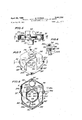
- FIG. 5 is a sectional view of another embodiment of the invention taken along the line V-V of FIG. 7;
- FIG. 6 is a fragmentary enlarged sectional view of the embodiment of FIG. 5;
- FIG. 7 is a top plan view of FIG. 5 in a stage wherein the cop-receiving opening therein is of minimum size; and FIG. 8 is a sectional view taken along the line III-VIII in FIG. 5 wherein the device of my invention is shown in a stage in which the cop-receiving opening therein is of maximum size.
- FIG. 4 there is shown a yarn-package winding machine which, except for the provision of a yarn seizing device according to the invention, corresponds substantially to the machine illustrated and described in Patent No. 3,111,280 of Reiners and Fiirst, assigned to the assignee of the present invention (FIG. 14 of the patent corresponding to the present FIG. 4 with the exception of the added device constructed in accordance with the present invention).
- the multistation winding machine of which only one winding station is shown in FIG. 4, comprises a frame structure with standards 1 on top of which an inclined table 2 is mounted.
- a magazine container 4 placed upon the table contains a number of spinning cops K vertically piled up in each magazine chamber, the cop axes being substantially horizontal.
- the cops drop individuallythrough an opening in the bottom of the magazine to a position K Thereafter the cop passes to a position K and through a chute a onto a feeder conveyor consisting of an endless chain provided with a number of troughs 7a for receiving the respective cops in the position shown at K
- the conveyor runs along the individual winding stations to supply them with cops whenever needed.
- Each individual winding station mounted on the machine frame structure 11 comprises a frame 12 pivotally mounted at 12a in which a take-up spool 13 is journalled.
- the yarn coming from the cop, then in position K passes through a tensioner 18 and over a guiding drum 14 onto the take-up spool 13.
- the spool 13 rests against the guiding drurn 14 and is frictionally entrained thereby to rotate at constant peripheral speed while the yarn, passing through a guiding groove of the drum 14, is reciprocated along the take-up spool in order to form the desired yarn package.
- the yarn supplying cop K is held on a spear or mandrel 19.
- the mandrel is mounted on a shaft 19a by means of which it can be rotated from the illustrated position of cop K; to a donning position where the mandrel 19 extends parallel to a trough-shaped slideway 23.
- Such rotational motion of the mandrel is effected only after a depleted cop, or rather the remaining tubular core thereof, has been dolfed from the mandrel.
- the slide 23 is upwardly extended by a trough-shaped slideway 25 upon which a new supply cop K is kept ready.
- the cop on slideway 25, however, is normally stopped by a latch 24.
- the latch 24 is moved downwardly to permit the cop to slide from position K on slideaway 25 downwardly onto the mandrel 19, after which the mandrel is turned upwardly to place the cop into the unwinding position K
- the feeder conveyor comprises an endless chain of individual members each of which forms or holds one of the troughs 7a. Each trough receives a single cop in an upright and nearly vertical position. Pivotally mounted at the lower end of each conveyor trough 7a is a closure member 39 which retains the cup in the trough 7a.
- a feeler device (not illustrated) is activated to open the closure member 39 so that the cop drops from position K in the conveyor trough 7a onto the slide 25 Where it is held in the position K tobe available when the cop now being unwound in this particular winding station is there after depleted.
- the machine is identical with the one illustrated and described in the above-mentioned Patent No. 3,111,280.
- a yarn seizing device comprising an annular nozzle member is mounted between the conveyor trough 7a and the slideway 25 so that the cop when dropping from the position K to the position K will pass coaxially through the substantially circular opening in the nozzle member.
- FIG. 1 of the drawing there is shown an embodiment of the pneumatic device for seizing a starting length of yarn wound on a cop, wherein there is provided a suction air channelor passage 54 which surrounds an annular slot 53 formed on the inner periphery of the illustrated device, the suction air passage 54 having the shape of a loop.
- a suction tube 60 connected to a vacuum pump or the like communicates with the suction air passage or channel 54 at a location at which a sector-shaped adjusting member 61 is disposed in a suitably shaped recess, the sector-shaped adjusting member 61 being secured below a circular disc 12 which can be pivoted by an adjusting lever 13.
- a suction air channelor passage 54 which surrounds an annular slot 53 formed on the inner periphery of the illustrated device, the suction air passage 54 having the shape of a loop.
- a suction tube 60 connected to a vacuum pump or the like communicates with the suction air passage or channel 54 at a location at which a sector-shaped adjusting member 61
- the suction current flows in the direction of the solid arrow 55 through the suction air channel or passage 54 and the suction tube 160.
- the lever 63 is pivoted in the direction of the curved arrow 63a i.e. counterclockwise as shown in FIG. 1, to the position thereof shown in phantom, the adjusting member 61 assumes the phantom position 61 so that the suction air current within the suction channel or passage 54 assumes the direction indicated by the dot-dash arrow 55'.
- the embodiment of my invention as shown in FIG. 1 has the advantage that the suction air current is guided particularly desirably from the standpoint of its flow characteristics.
- a disadvantage of the embodiment of FIG. 1, however, is that it is widely extended and therefore requires much space. To remove this disadvantage, it is possible to locate the suction tube 60 perpendicular to and substantially below the pivot point 63b of the adjusting member 61 and to provide the adjusting member 61 with a surface shape desirable for reversing the direction of the air current.
- the embodiment shown in FIG. 1 has a disadvantage in that a dead space or angle is formed between the walls 54- and 54 of the suction air passage or channel 54 surrounding in a loop the annular nozzle means or slot 53. The starting length of the yarn is unable to be seized in the dead angle or space between the walls 54 and 54" with any degree of reliability under all operating conditions.
- FIGS. 2 and 3 An embodiment which avoids the aforementioned disadvantages of the embodiment of FIG. 1, is shown in FIGS. 2 and 3, wherein the suction air channel or passage 104 extends concentrically about the annular nozzle means or slot 103.
- the suction tube 110 is connected with the suction channel or passage 104 so that the center lines of the suction tube 110 and of the suction channel or passage 104 in the vicinity of the adjusting member 144, which corresponds to the adjusting member 61 of the embodiment of FIG. 1, perpendicularly intersect one another.
- a portion of the suction channel or passage 104 is formed by a cover-like member 141 which is turnably mounted in a substantially circular groove 142 of the lower portion 43.
- the adjusting member 144 for controlling the flow direction of the suction air current within the passage 104 is mounted on the cover 141.
- the suction air current flows in the direction of the solid arrow around the annular slot or nozzle opening means 103 and through the suction channel or passage 104 and the suction tube 110.
- the cover 141 By merely turning the cover 141 in a clockwise direction as viewed in FIG. 3, the adjusting member 144 is moved to the phantom position shown at 144' so that the suction air current flows in the direction of the dot-dash arrow 105 through the suction channel or passage 104.
- FIGS. 2 and 3 are considerably more advantageous than that of the embodiment of FIG. 1 because there is practically no dead angle or space in the embodiment of FIGS. 2 and 3 in the vicinity of the annular slot or nozzle means 103.
- the type of construction of the embodiment of FIGS. 2 and 3 requires substantially less space than that of FIG. 1.
- the downwardly inclined arrangement of the suction tube is significant because when so constructed and employed in conjunction with a suitably formed surface of the adjusting member 144, it is possible to obtain good reversal of the suction air current through the suction air channel or passage 104 into the suction tube 110
- FIGS. 2 and 3 show an embodiment of the invention which particularly avoids certain disadvantages of the embodiment of FIG. 1.
- FIGS. 2 and 3 particularly in the arrangement and construction of the adjusting member 144, can nevertheless be modified within the scope of my invention without losing any of the advantages of this embodiment over that of FIG. 1.
- the adjusting member 144 be secured to the cover 141 but, rather, it can also be pivotally disposed, independently of the cover 141, as a separate component in the junction location of the suction tube 110 with the suction channel or passage 104.
- the suction tube 110 and an adjusting member 144 secured in the lower portion 143 of the suction channel 104 be pivotable relative to one another so as to be able to control the desired flow direction of the suction air.
- needle or pin members in the form of barbs having tips which point in the direction of the suction air current can be provided advantageously within the nozzle opening means or slot 53 or 103 of the embodiments of the instant application.
- annular slot 203 surrounded by a suction channel 204 communicating with a suction tube 210.
- an adjusting member 211 is disposed which can be pivoted by an adjusting lever 213 so as to determine the fiow direction of the suction air current within the suction channel 204 through an aperture 211a formed in the adjusting member 211.
- needles or pins 208 in the form of barbs are located within the annular slot 203 on which the starting length of yarn wound on a cop which has been sucked into the air passage 204 can be caught so as to prevent it from being pulled back out of the suction nozzle opening 203 again.
- These needles 208 are so disposed that they eX- tend along the entire annular slot 203 for any size of the opening 250 through which the cop passes as its starting length of yarn is being seized.
- the annular slot 203 with the suction channel 204 surrounding it, is defined by two portions 251, 252 of the suction air nozzle member which are adjustable relative to one another for varying the size of the opening 250 through which the cop is passed.
- each of the portions 251 and 252 be formed with an upper and a lower half.
- the upper half of the portion 251 is denoted as 251a and the lower half as 251b. Both halves of the portion 251 are held together by screws 261.
- the other portion 252 of the suction air nozzle member is compressed of the two halves 252a and which are in turn held together by screws 262.
- both portions 251 and 252 which are adjustable relative to one another are mutually slidable or telescope one within the other.
- a part of the suction channel wall of one portion 251 of the suction nozzle member, and in fact a part of the inner wall 2510 shown in FIG. 8, serves as a guide for the other portion 252 of the suction nozzle member.
- parts 251] and 251g of the suction channel wall of the portion 251 serving as the guide are elongated along the channel length and overlap the wall of the portion 252 even when the opening 250 through which the cop passes has been increased to its maximum size as shown clearly in FIG. 8.
- the illustrated, particularly advantageous triangular shape of the parts 251] and 251g good guidance is provided for the portion 252, in spite of the fact that the outer contour of the entire pneumatic device is not altered even for the smallest suction channel cross section.
- the suction channel cross section in which the portion 251 of the suction nozzle member serves as the guide along the entire displacement or slide path 251d of the other portion 252, is uniform.
- the term displacement or slide path corresponds to the amount of overlap of the suction channel between the portions 251 and 252 in the stage shown in FIG. 7 wherein the smallest opening possible for a cop to pass therethrough is provided.
- the displacement or slide length 2512 represents the length of the displacement path which is effected between the stages wherein the opening 250 for passage of the cop is largest and smallest.
- the slide or displacement length is marked on the surface of the portion 252 by a scale 252a.
- the point 251h of the triangular part 251g or of the guide contour 264 secured thereon slides past the scale 252c during the adjustment of the opening through which the cop passes, so that for a specific diameter of the cop, the correct displacement or slide length can readily be adjusted.
- the suction channel cross section for the portion 251 which is joined with the suction tube 210 is greater than for the other portion 252.
- the center line M of the suction channel of each portion 251, 252 can actually be curved along the displacement or slide path, however it is then necessary that at least that part of the channel wall of the portion 252, which is slidable in the portion 251, should be formed of elastic material. It is more advantageous and constructively simpler, however, if the center line M of the suction channel of each portion 251, 252 of the embodiment of FIGS. 5 through 8 forms a straight line along the entire displacement or slide path 251d.
- both portions 251, 252 of the suction air nozzle member automatically produces an opening 250 for passage of the cop which cannot have a constant clearance for the cop for all diameters thereof.
- a particular advantageous solution is afforded by providing the opening 250 with a form similar to a hexagon for maximum size of the opening 250 as shown in FIG. 8.
- Two sides 253, 254 of the hexagon are located parallel to the displacement or slide path 251d and are obviously spaced from the cop in the stage wherein the opening 250 is of maximum size as shown in FIG. 8.
- the engagement locations 255, 256 of the pairs of sides of the hexagon bordering on the parallel sides 253 and 254 are curved to correspond to the smallest possible diameter of a cop which is to pass through the opening 250. As shown in FIG.
- the opening 250 is contracted into a shape which is substantially that of a quadrilateral because the sides 253 and 254 of the hexagon, parallel to the displacement or slide path 251d, produce no efiect upon the annular slot or nozzle means 203. As is especially apparent from FIG.
- both portions 251 and 252 of the suction nozzle member in respectively two halves 251a and 251b, on the one hand, and 252a and 252b, on the other hand, the wall of the suction channel in the vicinity of the displacement or slide path can be constructed in the form of a labyrinth seal 263, so that a good sealing effect can be obtained.
- the transition from one portion 251 to the other portion 252 of the nozzle member in the vicinity of the annular slot or nozzle opening means 203 is particularly difiicult.
- FIG. 6 part of FIG. 5 is shown in an enlarged view in FIG. 6.
- FIG. 6' the Walls of the parts 252a and 25% of the portion 252 as well as the walls of the parts 251a and 2511) of the portion 251, which surround the annular slot 203.
- the aforementioned needles 208 can be clearly seen in FIG. 6, located both in the part 251b as well as the part 25212.
- FIG. 6 Also shown in FIG. 6 is the construction of the yarn deflecting members 259 and 260 which cover the annular slot 203 at the engagement locations 257 and 258 (FIGS. 7 and 8) in order to prevent the yarn from being caught in the engagement locations 257 and 258.
- the shape of the yarn deflecting member 259 which is formed of sheet metal is shown in dotted lines in the plan view of FIG. 7.
- the yarn deflecting member 260 also formed of sheet metal, is shown in FIG. 8 in dotted lines, although according to the cross sectional view of FIG. 8, it should normally be located above the sectional plane of the drawing, a fact which should not be difficult to ascertain from FIG. 5.
- many specially advantageous features are shown in the embodiment of FIGS. through 8, nevertheless, these features can have different forms from that shown in the figures.
- the sliding of the cop through the opening 250 can be facilitated by providing a guiding contour 264.
- the cross section of the suction channel surrounding the annular slot gradually increases in the direction of the suction air current so that the strength of the suction air current in the entire nozzle opening means or annular slot is constant.
- measures must be taken for ensuring a continuous increasing of the suction channel cross section in the direction of the suction air current for both flow directions of the suction air current through the air passage or channel.
- the invention of the instant application is based upon recognition of the fact that a constant cross section of the suction channel surrounding the annular slot produces in practice sufiiciently constant strength of the suction air current in the annular slot when the cross section of the suction channel surrounding the annular slot is sufficiently large with respect to the cross section of the annular slot.
- the suction air current can flow in the suction channel surrounding the annular slot in one direction or in a direction opposite thereto so that, in fact, cops having an S-winding or a Z-winding of the starting length of the yarn can be securely seized without having togreatly complicate a device such as that disclosed in my aforementioned copending application in order to attain this improvement.
- Pneumatic device for seizing a starting length of yarn wound on a cop, comprising a suction nozzle member of substantially annular shape defining a suction air passage having given characteristics of length and air flow direction, said member being formed with nozzle opening means communicating with said air passage and extending annularly along the inner periphery of said member so as to surround a cop wound with yarn having a starting length to be seized, means for placing the cop in substantially coaxial relation to said annular nozzle member, said nozzle member and the cop located substantially coaxial therewith being movable relative to one another in the axial direction thereof, and said nozzle member having adjusting means for varying at least one of the given characteristics of length and air flow direction of said suction air passage.
- said suction air passage is substantially annular, and including means connected to said suction nozzle member and communicating at a given location with said substantially annular suction air passage for applying suction thereto, said adjusting means comprising a blocking member mounted in said air passage at said given location and selectively movable into a position at one side of said given location blocking suction air flow between said air passage at said one side and said suction-applying means.
- Yarn-seeking device including a suction tube connected to said suction nozzle member and communicating at a given location with said suction air passage for applying suction thereto, said suction air passage being concentric to said annular nozzle opening means, said adjusting means comprising a blocking member mounted in said suction air passage at said given location and selectively movable into a position at one side of said location so as to block suction air flow between said suction air passage at said one side and said suction tube, said suction tube having a longitudinal axis and said annular suction air passage having a substantially circular center line, said suction tube axis being substantially perpendicular to the substantially circular center line of said suction air passage.
- said substantially annular suction nozzle member defines an opening, wherein the cop is received, and is formed of at least two portions each defining part of the length of said suction air passage and part of said nozzle opening means, said portions of said suction nozzle member being movable relative to one another for varying the size of the cop-receiving opening.
- one of said portions is slidingly received in the other of said portions, and including means for applying suction to said suction air passage connected to said other portion, the suction air passage defined by said other portion having a cross section greater than that of the suction air passage defined by said one portion.
Landscapes
- Engineering & Computer Science (AREA)
- Textile Engineering (AREA)
- Spinning Or Twisting Of Yarns (AREA)
Description
A ril 29, 1969 w. KUPPER 3,441,230
PNEUMATIC DEVICE FOR SEIZING A STARTING LENGTH OF YARN WOUND ON A COP Filed May 25, 1967 Sheet of 3 A ril 29, 1 969 PNEUMATIC DEVIC Filed May 25, 1967 W. KUPPER OF YARN WOUND ON A COP llO FIG. 4
E FOR SEIZING A STARTING LENGTH Sheet 2 NNNAVNAV AV ofS April 29, 1969 w. KUPPER 3,441,230
PNEUMATIC DEVICE FOR SEIZING A STARTING LENGTH OF YARN WOUND ON A COP Filed May 25, 1967 Sheet 3 of 3 F/C-Z5 M United States Patent 01 lice 3,441,230 Patented Apr. 29, 1969 US. Cl. 242-35.6 12 Claims ABSTRACT OF THE DISCLOSURE Pneumatic device for seizing a starting length of yarn wound on a cop includes a suction nozzle member of substantially annular shape defining a suction air passage having given characteristics of length and air-flow direction, the member being formed with nozzle opening means communicating with the air passage and extending annularly along the inner periphery of the member so as to surround a cop wound with yarn having a starting length to be seized. Means are provided for placing the cop in substantially coaxial relation to the annular nozzle member, the nozzle member and the cop located substantially coaxial therewith being movable relative to one another in the axial direction thereof, and the nozzle member having adjusting means for varying at least one of the given characteristics of length and air-flow direction of the suction air passage.
My invention relates to device for seizing by means of a suction nozzle the starting length of yarn wound on a spinning cop or similar coil of yarn.
In my copending application Ser. No. 539,394, filed Apr. 1, 1966, now Patent No. 3,388,872, I have described a device for seizing the starting length of yarn wound on a cop by means of a suction nozzle having a nozzle opening in the form of an annular slot surrounding the cop, the nozzle opening and the cop being movable relative to one another. In the illustrated and described embodiment of my afore-mentioned copending application, the suction channel has the shape of a spiral about the annular suction slot. Because of this spiral shape, suction air current entering the suction channel through the annular slot exerts a component force tangential to the peripheral surface of the cop so that the starting length of yarn is not only seized and raised from the cop butis, furthermore, able to be unwound therefrom. Unwinding of the starting length of yarn is actually not required for all types of yarn and cop windings, since, for example, in the case where the starting length has an outer reverse helical winding which is very steep, a sutficient length of yarn is freed for drawing the starting length of yarn far enough into the suction nozzle due to the relative motion between the cop and the nozzle opening. Nevertheless, it has been found that when the starting lengths of various types of yarn or cop windings are capable of being unwound by the device, the reliability of seizing the starting length of the yarn is increased. In such cases, however, it has been found to be disadvantageous that the device described in my aforementioned copending application only permits unwinding of the starting length of the yarn for cops having a specific direction of winding. Thus,
depending upon the direction of flow of the suction air current in the suction channel surrounding the annular slot, the device of the copending application can either unwind a cop having an S-winding or a cop having a Z-winding, but not both.
Another disadvantage of the device of my aforementioned copending application is that reliable seizure of the starting length of yarn can only be achieved by greatly increasing the power of the suction airflow when attempting to seize the starting lengths of cops whose outer diameter is much smaller than the smallest inner diameter of the suction nozzle opening in the device through which the cop passes. A proposal has been made for avoiding this disadvantage by varying the opening surrounded by the annular slot through which the cop passes by means of adjustable inserts which increase or decrease the radial length of the annular slot in the direction of the opening through which the cop passes. The assembly operations necessary therefor, however, require considerable time expenditure and are economically feasible only if cops of the same diameter are being continually processed through the device for a long period.
It is accordingly an object of my invention to provide device for pneumatically seizing with the same high degree of reliability a starting length of yarn that is either wound on a cop with an S-type winding or a Z-type Winding.
It is another object of my invention to provide a device for pneumatically seizing a starting length of yarn wound on a cop wherein the size of the opening through which the cop passes through the device is accommodated in the simplest manner possible to cops of varying diameters.
With the foregoing and other objects in view I accordingly provide pneumatic device for seizing a starting length of yarn wound on a cop, comprising a suction nozzle member of substantially annular shape defining a suction air passage having given characteristics of length and airflow direction, the member being formed with nozzle opening means communicating with the air passage and extending annularly along the inner periphery of the member so as to surround a cop Wound with yarn having a starting length to be seized. Also provided are means for placing the cop in substantially coaxial relation to the annular nozzle member, the nozzle member and the cop located substantially coaxial therewith being movable relative to one another in the axial direction thereof, and the nozzle member having adjusting means for varying at least one of the given characteristics of length and airflow direction of the suction air passage.
In accordance with a more particular aspect of my invention, I provide device wherein the suction air passage or canal surrounding the annular nozzle opening means or slot has a substantially uniform cross section, and means, such as a suction tube, is connected to the suction nozzle member and communicates at a given location with the substantially annular suction air passage for applying suction thereto, the adjusting means comprising a blocking member mounted in the air passage at the given location and selectively movable into a position at one side of the given location blocking suction air flow between the air passage at the one side and the suction-applying means.
According to a further aspect of the invention, I provide pneumatic device for seizing a starting length of yarn wound on a cop wherein a substantially annular suction nozzle member defines an opening in which the cop is received, and is formed of at least two portions each defining part of the length of the suction air passage and part of the nozzle opening means, the portions of the suction nozzle member being movable relative to one another for varying the size of the cop-receiving opening. Consequently, a change in the opening through which the cop passes can be effected similar to that of an iris diaphragm or shutter by means of a suitable number of adjustable component portions or members of the suctlon nozzle member.
Inasmuch as an iris diaphragm-type structure is quite expensive and has the further disadvantage that it is susceptible readily to breakdown due to the accumulation of fiber waste or similar causes during performance of a textile processing operation, and the sealing of the suction channel or passage surrounding the annular nozzle opening or slot is very difficult to effect, a further feature of my invention is to form the suction nozzle member of two portions one of which is slidingly or telescopically received in the other, the suction air passage defined by the other of the portions having a wall serving at least partly as a guide for the one portion.
In accordance with yet another feature of the invention, the suction air passage wall of the nozzle member portion serving as a guide for the other nozzle member portion has an extension located along the length of the suction air passage which is of such length as to remain in overlapping relation to the wall of the portion of the nozzle member guided therein even when the size of the copreceiving opening is a maximum so that the other portion is reliably guided at all times.
If the suction air flow as provided in my aforementioned copending application is only in one direction around the annular slot or nozzle opening means, it is possible also in the case of the invention of the instant application to increase the cross section of the suction air passage in the direction of the suction air flow. Difficulties arise, however, therefrom at the transition locations between the two portions of the suction nozzle member according to the invention, because turbulent air flow forms at these locations and sealing of the suction air passage presents great difficulties. It is therefore advantageous for the cross section of the air suction passage in the portion of the suction nOZZle member which serves as the guide to be constant or uniform along the entire length along which it is guided. This telescoping bipartite embodiment of the invention can also be provided with a blocking member mounted in the suction air passage at the junction thereof with a suction tube for applying suction to the air passage, so as to adjust the flow direction of the suction air current through the passage so that the suction air current is passed either in one or the other rotary direction through the air passage about the annular nozzle opening means or slot. When using such a blocking member it is also desirable that the cross section of the suction air passage be constant not only along the length of the portion of the nozzle member serving as the guide for the other portion but rather in both entire portions of the suction air passage nozzle. However, since the portions of the nozzle are telescoping, in order to achieve the most desirable flow characteristics for the cross section of the air suction passage of that portion of the nozzle member which is connected to the suction tube applying suction to the air passage, it is advantageous for it to be of greater cross section than that of the other portion of the suction nozzle. In accordance with an additional feature of my invention which simplifies the construction thereof, I provide a bipartite suction nozzle wherein the centerline of the suction air passage of each portion of the nozzle is a straight line along the entire displacement path between the two portions thereof.
In accordance with yet another feature of the invention, and in order to have the annular nozzle means or slot as close as possible to the cop, the opening through which the cop passes is given a geometrical form similar to that of a hexagon. The substantially hexagonal opening, when of maximum size, has two sides parallel to th direction of displacement of the telescoping portions of the suction nozzle member, and the vertices of the two remaining pairs of sides of the substantially hexagonal opening are rounded out so as to accommodate a cop having a minimal diameter when the opening has a minimal size. By providing an opening of such substantially hexagonal shape, the annular nozzle opening means or slot can be located optimally close to cops having diameters ranging from the smallest to the largest so that the locations at which the annular slot or nozzle opening means are spaced farther from the cop simultaneously afford the advantage that the cops cannot be rigidly sucked up against the annular slot or nozzle opening means.
To prevent clamping the starting length of the yarn, which has been sucked into the suction air passage of the telescoping bipartite suction nozzle member, in accordance with a further feature of my invention independent of the aforementioned advantageous shapes of the device of my invention, I provide the annular slot or nozzle opening means, at the locations whereat the portions of the suction nozzle member engage with one another, with a yarn deflecting member such as a plate or a wire, for example, which covers the annular slot or nozzle openings.
Other features which are considered as characteristic for the invention are set forth in the appended claims.
Although the invention is illustrated and described here in as pneumatic device for seizing a starting length of yarn wound on a cop, it is nevertheless not intended to be limited to the details shown, since various modifications and structural changes may be made therein without departing from the spirit of the invention and within the scope and range of equivalents of the claims.
The construction and method of operation of the invention, however, together with additional objects and advantages thereof will be best understood from the following description of specific embodiments when read in connection with the accompanying drawings, in which:
FIG. 1 is a plan view of a suction nozzle device constructed in accordance with my invention;
FIG. 2 is a sectional view of another embodiment of the device of FIG. 1 taken along the line II-II in FIG. 3;
FIG. 3 is a plan view of the embodiment of FIG. 2;
FIG. 4 is a schematic side-elevational view of a cheesewinding machine equipped with a device constructed in accordance with the invention and corresponding to the embodiment shown in FIGS. 2 and 3;
FIG. 5 is a sectional view of another embodiment of the invention taken along the line V-V of FIG. 7;
FIG. 6 is a fragmentary enlarged sectional view of the embodiment of FIG. 5;
FIG. 7 is a top plan view of FIG. 5 in a stage wherein the cop-receiving opening therein is of minimum size; and FIG. 8 is a sectional view taken along the line III-VIII in FIG. 5 wherein the device of my invention is shown in a stage in which the cop-receiving opening therein is of maximum size.
Referring now to the drawings and first to FIG. 4, there is shown a yarn-package winding machine which, except for the provision of a yarn seizing device according to the invention, corresponds substantially to the machine illustrated and described in Patent No. 3,111,280 of Reiners and Fiirst, assigned to the assignee of the present invention (FIG. 14 of the patent corresponding to the present FIG. 4 with the exception of the added device constructed in accordance with the present invention).
The multistation winding machine of which only one winding station is shown in FIG. 4, comprises a frame structure with standards 1 on top of which an inclined table 2 is mounted. A magazine container 4 placed upon the table contains a number of spinning cops K vertically piled up in each magazine chamber, the cop axes being substantially horizontal. The cops drop individuallythrough an opening in the bottom of the magazine to a position K Thereafter the cop passes to a position K and through a chute a onto a feeder conveyor consisting of an endless chain provided with a number of troughs 7a for receiving the respective cops in the position shown at K The conveyor runs along the individual winding stations to supply them with cops whenever needed.
Each individual winding station mounted on the machine frame structure 11 comprises a frame 12 pivotally mounted at 12a in which a take-up spool 13 is journalled. The yarn coming from the cop, then in position K passes through a tensioner 18 and over a guiding drum 14 onto the take-up spool 13. The spool 13 rests against the guiding drurn 14 and is frictionally entrained thereby to rotate at constant peripheral speed while the yarn, passing through a guiding groove of the drum 14, is reciprocated along the take-up spool in order to form the desired yarn package. Details with respect to design and operation of such yarn winding machines are provided in the above-mentioned Patent No. 3,111,280 as well as in Patent No. 2,994,491, for example.
During the winding operation, the yarn supplying cop K is held on a spear or mandrel 19. The mandrel is mounted on a shaft 19a by means of which it can be rotated from the illustrated position of cop K; to a donning position where the mandrel 19 extends parallel to a trough-shaped slideway 23. Such rotational motion of the mandrel is effected only after a depleted cop, or rather the remaining tubular core thereof, has been dolfed from the mandrel. The slide 23 is upwardly extended by a trough-shaped slideway 25 upon which a new supply cop K is kept ready. The cop on slideway 25, however, is normally stopped by a latch 24. For cop exchange, the latch 24 is moved downwardly to permit the cop to slide from position K on slideaway 25 downwardly onto the mandrel 19, after which the mandrel is turned upwardly to place the cop into the unwinding position K As aforementioned, the feeder conveyor comprises an endless chain of individual members each of which forms or holds one of the troughs 7a. Each trough receives a single cop in an upright and nearly vertical position. Pivotally mounted at the lower end of each conveyor trough 7a is a closure member 39 which retains the cup in the trough 7a. When the trough 7a arrives at an individual winding station where the cop in slideway 25 has been previously released onto the mandrel 19, a feeler device (not illustrated) is activated to open the closure member 39 so that the cop drops from position K in the conveyor trough 7a onto the slide 25 Where it is held in the position K tobe available when the cop now being unwound in this particular winding station is there after depleted. With respect to the feeler device and other details just mentioned, the machine is identical with the one illustrated and described in the above-mentioned Patent No. 3,111,280.
In accordance with the present invention, a yarn seizing device comprising an annular nozzle member is mounted between the conveyor trough 7a and the slideway 25 so that the cop when dropping from the position K to the position K will pass coaxially through the substantially circular opening in the nozzle member. This will be more fully described with reference to the remaining figures of the drawing.
Referring to FIG. 1 of the drawing there is shown an embodiment of the pneumatic device for seizing a starting length of yarn wound on a cop, wherein there is provided a suction air channelor passage 54 which surrounds an annular slot 53 formed on the inner periphery of the illustrated device, the suction air passage 54 having the shape of a loop. A suction tube 60 connected to a vacuum pump or the like (not shown) communicates with the suction air passage or channel 54 at a location at which a sector-shaped adjusting member 61 is disposed in a suitably shaped recess, the sector-shaped adjusting member 61 being secured below a circular disc 12 which can be pivoted by an adjusting lever 13. In the illustrated stage of FIG. 1, the suction current flows in the direction of the solid arrow 55 through the suction air channel or passage 54 and the suction tube 160. If the lever 63 is pivoted in the direction of the curved arrow 63a i.e. counterclockwise as shown in FIG. 1, to the position thereof shown in phantom, the adjusting member 61 assumes the phantom position 61 so that the suction air current within the suction channel or passage 54 assumes the direction indicated by the dot-dash arrow 55'.
The embodiment of my invention as shown in FIG. 1 has the advantage that the suction air current is guided particularly desirably from the standpoint of its flow characteristics. A disadvantage of the embodiment of FIG. 1, however, is that it is widely extended and therefore requires much space. To remove this disadvantage, it is possible to locate the suction tube 60 perpendicular to and substantially below the pivot point 63b of the adjusting member 61 and to provide the adjusting member 61 with a surface shape desirable for reversing the direction of the air current. However, even in this case, the embodiment shown in FIG. 1 has a disadvantage in that a dead space or angle is formed between the walls 54- and 54 of the suction air passage or channel 54 surrounding in a loop the annular nozzle means or slot 53. The starting length of the yarn is unable to be seized in the dead angle or space between the walls 54 and 54" with any degree of reliability under all operating conditions.
An embodiment which avoids the aforementioned disadvantages of the embodiment of FIG. 1, is shown in FIGS. 2 and 3, wherein the suction air channel or passage 104 extends concentrically about the annular nozzle means or slot 103. The suction tube 110 is connected with the suction channel or passage 104 so that the center lines of the suction tube 110 and of the suction channel or passage 104 in the vicinity of the adjusting member 144, which corresponds to the adjusting member 61 of the embodiment of FIG. 1, perpendicularly intersect one another. In the illustrated embodiment of FIGS. 2 and 3, a portion of the suction channel or passage 104 is formed by a cover-like member 141 which is turnably mounted in a substantially circular groove 142 of the lower portion 43. At the location of the junction of the suction tube 110 with the suction air channel or passage 104, the adjusting member 144 for controlling the flow direction of the suction air current within the passage 104 is mounted on the cover 141. In the diagrammatically shown broken-line position of the adjusting member 144, the suction air current flows in the direction of the solid arrow around the annular slot or nozzle opening means 103 and through the suction channel or passage 104 and the suction tube 110. By merely turning the cover 141 in a clockwise direction as viewed in FIG. 3, the adjusting member 144 is moved to the phantom position shown at 144' so that the suction air current flows in the direction of the dot-dash arrow 105 through the suction channel or passage 104. It is apparent that the embodiment of FIGS. 2 and 3 is considerably more advantageous than that of the embodiment of FIG. 1 because there is practically no dead angle or space in the embodiment of FIGS. 2 and 3 in the vicinity of the annular slot or nozzle means 103. Moreover, the type of construction of the embodiment of FIGS. 2 and 3 requires substantially less space than that of FIG. 1. In this regard, the downwardly inclined arrangement of the suction tube is significant because when so constructed and employed in conjunction with a suitably formed surface of the adjusting member 144, it is possible to obtain good reversal of the suction air current through the suction air channel or passage 104 into the suction tube 110 As aforementioned, FIGS. 2 and 3 show an embodiment of the invention which particularly avoids certain disadvantages of the embodiment of FIG. 1. However, the embodiment of FIGS. 2 and 3, particularly in the arrangement and construction of the adjusting member 144, can nevertheless be modified within the scope of my invention without losing any of the advantages of this embodiment over that of FIG. 1. Thus, for example, it is unnecessary that the adjusting member 144 be secured to the cover 141 but, rather, it can also be pivotally disposed, independently of the cover 141, as a separate component in the junction location of the suction tube 110 with the suction channel or passage 104. It is similarly possible to provide that the suction tube 110 and an adjusting member 144 secured in the lower portion 143 of the suction channel 104 be pivotable relative to one another so as to be able to control the desired flow direction of the suction air. Furthermore, just as in the embodiment of the invention disclosed in my aforementioned copending application, needle or pin members in the form of barbs having tips which point in the direction of the suction air current can be provided advantageously within the nozzle opening means or slot 53 or 103 of the embodiments of the instant application.
In the embodiment of FIGS. 5 through 8, there is provided an annular slot 203 surrounded by a suction channel 204 communicating with a suction tube 210. At the junction of the suction channel 204 with the suction tube 210, an adjusting member 211 is disposed which can be pivoted by an adjusting lever 213 so as to determine the fiow direction of the suction air current within the suction channel 204 through an aperture 211a formed in the adjusting member 211. As aforementioned, needles or pins 208 in the form of barbs are located within the annular slot 203 on which the starting length of yarn wound on a cop which has been sucked into the air passage 204 can be caught so as to prevent it from being pulled back out of the suction nozzle opening 203 again. These needles 208 are so disposed that they eX- tend along the entire annular slot 203 for any size of the opening 250 through which the cop passes as its starting length of yarn is being seized.
The annular slot 203, with the suction channel 204 surrounding it, is defined by two portions 251, 252 of the suction air nozzle member which are adjustable relative to one another for varying the size of the opening 250 through which the cop is passed. For reasons of manufacturing technique it can thereby be advantageous if, in accordance with the emobdment of FIGS.
5 through 8, each of the portions 251 and 252 be formed with an upper and a lower half. In FIGS. 5 through 8, the upper half of the portion 251 is denoted as 251a and the lower half as 251b. Both halves of the portion 251 are held together by screws 261. The other portion 252 of the suction air nozzle member is compressed of the two halves 252a and which are in turn held together by screws 262.
As can be seen more clearly from FIGS. 7 and 8, both portions 251 and 252 which are adjustable relative to one another are mutually slidable or telescope one within the other. A part of the suction channel wall of one portion 251 of the suction nozzle member, and in fact a part of the inner wall 2510 shown in FIG. 8, serves as a guide for the other portion 252 of the suction nozzle member. In order to maintain troublefree guidance of the portion 252 even for maximum size of the opening 250 through which the cop passes, parts 251] and 251g of the suction channel wall of the portion 251 serving as the guide are elongated along the channel length and overlap the wall of the portion 252 even when the opening 250 through which the cop passes has been increased to its maximum size as shown clearly in FIG. 8. By means of the illustrated, particularly advantageous triangular shape of the parts 251] and 251g, good guidance is provided for the portion 252, in spite of the fact that the outer contour of the entire pneumatic device is not altered even for the smallest suction channel cross section.
It is also to be seen from FIGS. 7 and 8 that the suction channel cross section, in which the portion 251 of the suction nozzle member serves as the guide along the entire displacement or slide path 251d of the other portion 252, is uniform. The term displacement or slide path corresponds to the amount of overlap of the suction channel between the portions 251 and 252 in the stage shown in FIG. 7 wherein the smallest opening possible for a cop to pass therethrough is provided. The displacement or slide length 2512, on the other hand, represents the length of the displacement path which is effected between the stages wherein the opening 250 for passage of the cop is largest and smallest. The slide or displacement length is marked on the surface of the portion 252 by a scale 252a. The point 251h of the triangular part 251g or of the guide contour 264 secured thereon slides past the scale 252c during the adjustment of the opening through which the cop passes, so that for a specific diameter of the cop, the correct displacement or slide length can readily be adjusted.
It can furthermore be noted from FIGS. 5 through 8 that the suction channel cross section for the portion 251 which is joined with the suction tube 210 is greater than for the other portion 252. The center line M of the suction channel of each portion 251, 252 can actually be curved along the displacement or slide path, however it is then necessary that at least that part of the channel wall of the portion 252, which is slidable in the portion 251, should be formed of elastic material. It is more advantageous and constructively simpler, however, if the center line M of the suction channel of each portion 251, 252 of the embodiment of FIGS. 5 through 8 forms a straight line along the entire displacement or slide path 251d.
The linear displaceability of both portions 251, 252 of the suction air nozzle member automatically produces an opening 250 for passage of the cop which cannot have a constant clearance for the cop for all diameters thereof. A particular advantageous solution is afforded by providing the opening 250 with a form similar to a hexagon for maximum size of the opening 250 as shown in FIG. 8. Two sides 253, 254 of the hexagon are located parallel to the displacement or slide path 251d and are obviously spaced from the cop in the stage wherein the opening 250 is of maximum size as shown in FIG. 8. The engagement locations 255, 256 of the pairs of sides of the hexagon bordering on the parallel sides 253 and 254 are curved to correspond to the smallest possible diameter of a cop which is to pass through the opening 250. As shown in FIG. 7, in the stage of the suction nozzle member wherein the opening 250 through which the cop is to pass is for a cop of the smallest diameter, the opening 250 is contracted into a shape which is substantially that of a quadrilateral because the sides 253 and 254 of the hexagon, parallel to the displacement or slide path 251d, produce no efiect upon the annular slot or nozzle means 203. As is especially apparent from FIG. 5, by constructing both portions 251 and 252 of the suction nozzle member in respectively two halves 251a and 251b, on the one hand, and 252a and 252b, on the other hand, the wall of the suction channel in the vicinity of the displacement or slide path can be constructed in the form of a labyrinth seal 263, so that a good sealing effect can be obtained. With respect to sealing of the nozzle memher, the transition from one portion 251 to the other portion 252 of the nozzle member in the vicinity of the annular slot or nozzle opening means 203 is particularly difiicult.
In order to show the relationships more clearly, part of FIG. 5 is shown in an enlarged view in FIG. 6. Thus, there is clearly shown in FIG. 6', the Walls of the parts 252a and 25% of the portion 252 as well as the walls of the parts 251a and 2511) of the portion 251, which surround the annular slot 203. Furthermore, the aforementioned needles 208 can be clearly seen in FIG. 6, located both in the part 251b as well as the part 25212. Also shown in FIG. 6 is the construction of the yarn deflecting members 259 and 260 which cover the annular slot 203 at the engagement locations 257 and 258 (FIGS. 7 and 8) in order to prevent the yarn from being caught in the engagement locations 257 and 258. The shape of the yarn deflecting member 259 which is formed of sheet metal is shown in dotted lines in the plan view of FIG. 7. For purposes of clarity, the yarn deflecting member 260, also formed of sheet metal, is shown in FIG. 8 in dotted lines, although according to the cross sectional view of FIG. 8, it should normally be located above the sectional plane of the drawing, a fact which should not be difficult to ascertain from FIG. 5. Although many specially advantageous features are shown in the embodiment of FIGS. through 8, nevertheless, these features can have different forms from that shown in the figures. Thus, for example, it is possible to provide a substantially circular cross section for the suction channel 204 instead of the rectangular one shown in FIG. 5. Furthermore, as indicated in FIGS. 5 and 7, the sliding of the cop through the opening 250 can be facilitated by providing a guiding contour 264.
It is also noted that for the aforementioned embodiment of the invention in my copending application, the cross section of the suction channel surrounding the annular slot gradually increases in the direction of the suction air current so that the strength of the suction air current in the entire nozzle opening means or annular slot is constant. In order to obtain this constant strength of the suction air current in the nozzle opening means in the embodiment of the instant application, measures must be taken for ensuring a continuous increasing of the suction channel cross section in the direction of the suction air current for both flow directions of the suction air current through the air passage or channel. However, this creates considerable complications. The invention of the instant application is based upon recognition of the fact that a constant cross section of the suction channel surrounding the annular slot produces in practice sufiiciently constant strength of the suction air current in the annular slot when the cross section of the suction channel surrounding the annular slot is sufficiently large with respect to the cross section of the annular slot. In this case, with the embodiments of the invention of the instant application, depending upon the position of the adjusting blocking member, the suction air current can flow in the suction channel surrounding the annular slot in one direction or in a direction opposite thereto so that, in fact, cops having an S-winding or a Z-winding of the starting length of the yarn can be securely seized without having togreatly complicate a device such as that disclosed in my aforementioned copending application in order to attain this improvement.
I claim:
1. Pneumatic device for seizing a starting length of yarn wound on a cop, comprising a suction nozzle member of substantially annular shape defining a suction air passage having given characteristics of length and air flow direction, said member being formed with nozzle opening means communicating with said air passage and extending annularly along the inner periphery of said member so as to surround a cop wound with yarn having a starting length to be seized, means for placing the cop in substantially coaxial relation to said annular nozzle member, said nozzle member and the cop located substantially coaxial therewith being movable relative to one another in the axial direction thereof, and said nozzle member having adjusting means for varying at least one of the given characteristics of length and air flow direction of said suction air passage.
2. Yarn-seizing device according to claim 1 wherein said suction air passage surrounds said nozzle opening means and has a substantially uniform cross section.
3. Yarn-seizing device according to claim 1, wherein said suction air passage is substantially annular, and including means connected to said suction nozzle member and communicating at a given location with said substantially annular suction air passage for applying suction thereto, said adjusting means comprising a blocking member mounted in said air passage at said given location and selectively movable into a position at one side of said given location blocking suction air flow between said air passage at said one side and said suction-applying means.
4. Yarn-seeking device according to claim 1 including a suction tube connected to said suction nozzle member and communicating at a given location with said suction air passage for applying suction thereto, said suction air passage being concentric to said annular nozzle opening means, said adjusting means comprising a blocking member mounted in said suction air passage at said given location and selectively movable into a position at one side of said location so as to block suction air flow between said suction air passage at said one side and said suction tube, said suction tube having a longitudinal axis and said annular suction air passage having a substantially circular center line, said suction tube axis being substantially perpendicular to the substantially circular center line of said suction air passage.
5. Yarn-seizing device according to claim 1 wherein said substantially annular suction nozzle member defines an opening, wherein the cop is received, and is formed of at least two portions each defining part of the length of said suction air passage and part of said nozzle opening means, said portions of said suction nozzle member being movable relative to one another for varying the size of the cop-receiving opening.
6. Yarn-seizing device according to claim 5, wherein one of said portions is slidingly received in the other of said portions, the suction air passage defined by the other of said portions having a wall serving at least partly as a guide for said one portion.
7. Yarn-seizing device according to claim 5 wherein one of said portions is telescopically received in the other of said portions, the suction air passage defined by the other of said portions having a wall serving at least partly as a guide for said one portion, said guide wall being in overlapping relationship with said one portion even in the stage when the cop-receiving opening is of maximum SIZ6.
8. Yarn-seizing device according to claim 5 wherein one of said portions is telescopically received in the other of said portions, and the suction air passage defined by the other of said portions has means for guiding said one portion along a distance of predetermined length therein, said suction air passage having a constant cross section along substantially all of said predetermined length thereof.
9. Yarn-seizing device according to claim 5 wherein one of said portions is slidingly received in the other of said portions, and including means for applying suction to said suction air passage connected to said other portion, the suction air passage defined by said other portion having a cross section greater than that of the suction air passage defined by said one portion.
10. Yarn-seizing device according to claim 5 wherein one of said portions is slideable in the other of said portions along a slideway of predetermined length, said suction air passage in both of said portions along the entire length of said slideway having a rectilinear center line.
11. Yarn-seizing device according to claim 5, wherein one of said portions is slidable in the other of said portions along a slideway of predetermined length, and said cop-receiving opening has a substantially hexagonal shape,
two sides thereof being parallel to said slideway and being of said suction nozzle member are in engagement adspaced from one another so that a cop of maximum diamjacent said cop-receiving opening. eter passing through said cop-receiving opening remains spaced from said parallel sides, and two pairs of opposite References Cited sides respectively joining said two parallel sides of said 5 UNITED STATES PATENTS hexagonal Opening, the sides of each of said Pairs 2,892,470 6/1959 Corneliusson et al. 139-257 spectively having a curved junction corresponding to the 3 031 149 4/1962 Furst et 1 242 35 shape of a cop of smallest diameter to be passed through 3,111,280 11/ 1963 R i r t 242 35 5 said opening. 3,295,776 1/ 1967 Cruickshank et al.
12. Yarn-seizing device according to claim 5 including 10 3,329,362 7/1967 Kieronski 242-35.6
a yarn deflecting member covering said annular nozzle opening means at locations thereof Whereat said portions STANLEY GILREATH Primary Examiner
Applications Claiming Priority (2)
| Application Number | Priority Date | Filing Date | Title |
|---|---|---|---|
| DER0043353 | 1966-05-27 | ||
| DER0045086 | 1967-01-20 |
Publications (1)
| Publication Number | Publication Date |
|---|---|
| US3441230A true US3441230A (en) | 1969-04-29 |
Family
ID=25991974
Family Applications (1)
| Application Number | Title | Priority Date | Filing Date |
|---|---|---|---|
| US641185A Expired - Lifetime US3441230A (en) | 1966-05-27 | 1967-05-25 | Pneumatic device for seizing a starting length of yarn wound on a cop |
Country Status (1)
| Country | Link |
|---|---|
| US (1) | US3441230A (en) |
Cited By (4)
| Publication number | Priority date | Publication date | Assignee | Title |
|---|---|---|---|---|
| US4103836A (en) * | 1975-06-25 | 1978-08-01 | W. Schlafhorst & Co. | Undoing or removing the thread ends of textile bobbins |
| US4660780A (en) * | 1984-04-05 | 1987-04-28 | Murata Kikai Kabushiki Kaisha | Yarn end finding device |
| US4705224A (en) * | 1985-10-14 | 1987-11-10 | Kurashiki Boseki Kabushiki Kaisha | Apparatus for blowing a thread end off of a full cheese formed by an open-end spinning and winding machine |
| US4858836A (en) * | 1986-12-12 | 1989-08-22 | Murata Kikai Kabushiki Kaisha | Yarn end finding device |
Citations (5)
| Publication number | Priority date | Publication date | Assignee | Title |
|---|---|---|---|---|
| US2892470A (en) * | 1956-05-28 | 1959-06-30 | Rydboholms Aktiebolag | Method and means in looms for holding the weft end of a bobbin to be introduced into the shuttle |
| US3031149A (en) * | 1957-07-29 | 1962-04-24 | Reiners Walter | Method and means for readying a yarn coil to be unwound |
| US3111280A (en) * | 1957-08-19 | 1963-11-19 | Reiners Walter | Coil winding machine with automatic coil-exchanging and yarn-tying devices |
| US3295776A (en) * | 1964-10-07 | 1967-01-03 | Leesona Corp | Method and means for readying supply bobbins |
| US3329362A (en) * | 1962-10-12 | 1967-07-04 | Leesona Corp | Winding machine |
-
1967
- 1967-05-25 US US641185A patent/US3441230A/en not_active Expired - Lifetime
Patent Citations (5)
| Publication number | Priority date | Publication date | Assignee | Title |
|---|---|---|---|---|
| US2892470A (en) * | 1956-05-28 | 1959-06-30 | Rydboholms Aktiebolag | Method and means in looms for holding the weft end of a bobbin to be introduced into the shuttle |
| US3031149A (en) * | 1957-07-29 | 1962-04-24 | Reiners Walter | Method and means for readying a yarn coil to be unwound |
| US3111280A (en) * | 1957-08-19 | 1963-11-19 | Reiners Walter | Coil winding machine with automatic coil-exchanging and yarn-tying devices |
| US3329362A (en) * | 1962-10-12 | 1967-07-04 | Leesona Corp | Winding machine |
| US3295776A (en) * | 1964-10-07 | 1967-01-03 | Leesona Corp | Method and means for readying supply bobbins |
Cited By (4)
| Publication number | Priority date | Publication date | Assignee | Title |
|---|---|---|---|---|
| US4103836A (en) * | 1975-06-25 | 1978-08-01 | W. Schlafhorst & Co. | Undoing or removing the thread ends of textile bobbins |
| US4660780A (en) * | 1984-04-05 | 1987-04-28 | Murata Kikai Kabushiki Kaisha | Yarn end finding device |
| US4705224A (en) * | 1985-10-14 | 1987-11-10 | Kurashiki Boseki Kabushiki Kaisha | Apparatus for blowing a thread end off of a full cheese formed by an open-end spinning and winding machine |
| US4858836A (en) * | 1986-12-12 | 1989-08-22 | Murata Kikai Kabushiki Kaisha | Yarn end finding device |
Similar Documents
| Publication | Publication Date | Title |
|---|---|---|
| US3198446A (en) | Device for preventing double threads in automatic coil winding machines | |
| ES2949621T3 (en) | Procedure and device for threading a thread end onto a ring spool | |
| US3295775A (en) | Method and apparatus for readying the winding operation of yarn supply coils on coil winding machines | |
| US2998202A (en) | Initial thread end snagger | |
| US4041684A (en) | Device for automatically joining a thread for spinning | |
| CN101596990B (en) | Suction nozzle | |
| US4069983A (en) | Method and device for forming a bunch winding on a fresh bobbin at the time of a doffing and donning operation | |
| US5423170A (en) | Suction apparatus for withdrawing advancing yarns to a waste container | |
| US3441230A (en) | Pneumatic device for seizing a starting length of yarn wound on a cop | |
| US3408011A (en) | Thread reserve forming devices for thread winding mechanisms | |
| CN100577546C (en) | Textile machines for the production of cross-wound bobbins | |
| JPH03500308A (en) | Yarn storage and unwinding device | |
| JPS5815428B2 (en) | makiito souchi | |
| CN110857196B (en) | Yarn splicing device for a workstation of a textile machine for producing cross-wound bobbins | |
| US4267983A (en) | Thread draw-off apparatus | |
| US4081149A (en) | Mechanism for forming transfer tails on wound yarn packages | |
| US4060207A (en) | Yarn winding mechanism in spinning machine | |
| US6315236B1 (en) | Apparatus and method for guiding and cutting an advancing yarn during a package doff | |
| US4010702A (en) | Automatic threading device for sewing machines | |
| JP2019163164A (en) | Method of automatic yarn-piecing at fabric machine work station and fabric machine | |
| JPS6411732B2 (en) | ||
| US4339089A (en) | Yarn winding apparatus and method | |
| US4164115A (en) | Pneumatically operated yarn threading mechanisms for textile yarn processing machines | |
| US4002305A (en) | Device for forming a tail wind around a bobbin held by a take-up mechanism of a ringless spinning machine | |
| JPH10167575A (en) | Cop preparation device for yarn rewinder |