US3438468A - Single handle control mechanisms - Google Patents
Single handle control mechanisms Download PDFInfo
- Publication number
- US3438468A US3438468A US557336A US3438468DA US3438468A US 3438468 A US3438468 A US 3438468A US 557336 A US557336 A US 557336A US 3438468D A US3438468D A US 3438468DA US 3438468 A US3438468 A US 3438468A
- Authority
- US
- United States
- Prior art keywords
- control
- shaft
- throttle
- control member
- movement
- Prior art date
- Legal status (The legal status is an assumption and is not a legal conclusion. Google has not performed a legal analysis and makes no representation as to the accuracy of the status listed.)
- Expired - Lifetime
Links
- 230000007246 mechanism Effects 0.000 title description 18
- 230000033001 locomotion Effects 0.000 description 22
- 230000007935 neutral effect Effects 0.000 description 17
- 230000005540 biological transmission Effects 0.000 description 6
- 239000002184 metal Substances 0.000 description 2
- 230000008878 coupling Effects 0.000 description 1
- 238000010168 coupling process Methods 0.000 description 1
- 238000005859 coupling reaction Methods 0.000 description 1
- 210000003195 fascia Anatomy 0.000 description 1
- 230000004048 modification Effects 0.000 description 1
- 238000012986 modification Methods 0.000 description 1
- 230000000717 retained effect Effects 0.000 description 1
- 239000011435 rock Substances 0.000 description 1
Images


Classifications
-
- B—PERFORMING OPERATIONS; TRANSPORTING
- B63—SHIPS OR OTHER WATERBORNE VESSELS; RELATED EQUIPMENT
- B63H—MARINE PROPULSION OR STEERING
- B63H21/00—Use of propulsion power plant or units on vessels
- B63H21/21—Control means for engine or transmission, specially adapted for use on marine vessels
- B63H21/213—Levers or the like for controlling the engine or the transmission, e.g. single hand control levers
-
- B—PERFORMING OPERATIONS; TRANSPORTING
- B63—SHIPS OR OTHER WATERBORNE VESSELS; RELATED EQUIPMENT
- B63H—MARINE PROPULSION OR STEERING
- B63H21/00—Use of propulsion power plant or units on vessels
- B63H21/22—Use of propulsion power plant or units on vessels the propulsion power units being controlled from exterior of engine room, e.g. from navigation bridge; Arrangements of order telegraphs
-
- Y—GENERAL TAGGING OF NEW TECHNOLOGICAL DEVELOPMENTS; GENERAL TAGGING OF CROSS-SECTIONAL TECHNOLOGIES SPANNING OVER SEVERAL SECTIONS OF THE IPC; TECHNICAL SUBJECTS COVERED BY FORMER USPC CROSS-REFERENCE ART COLLECTIONS [XRACs] AND DIGESTS
- Y10—TECHNICAL SUBJECTS COVERED BY FORMER USPC
- Y10T—TECHNICAL SUBJECTS COVERED BY FORMER US CLASSIFICATION
- Y10T74/00—Machine element or mechanism
- Y10T74/18—Mechanical movements
- Y10T74/18056—Rotary to or from reciprocating or oscillating
- Y10T74/18208—Crank, pitman, and slide
-
- Y—GENERAL TAGGING OF NEW TECHNOLOGICAL DEVELOPMENTS; GENERAL TAGGING OF CROSS-SECTIONAL TECHNOLOGIES SPANNING OVER SEVERAL SECTIONS OF THE IPC; TECHNICAL SUBJECTS COVERED BY FORMER USPC CROSS-REFERENCE ART COLLECTIONS [XRACs] AND DIGESTS
- Y10—TECHNICAL SUBJECTS COVERED BY FORMER USPC
- Y10T—TECHNICAL SUBJECTS COVERED BY FORMER US CLASSIFICATION
- Y10T74/00—Machine element or mechanism
- Y10T74/20—Control lever and linkage systems
- Y10T74/20012—Multiple controlled elements
Definitions
- a single lever control mechanism including a housing with a main control shaft rotatably supported in the housing.
- a manual control handle is attached to the control shaft for rotating the control shaft in either direction from a neutral position.
- a first control member is rotatably supported by the housing and linkage means interconnects the control shaft and the first cont-rol member for rotating the first control member always in the same direction when the control shaft is rotated in either direction from the neutral position.
- a second control member is rotatably supported by the housing and a drive member is disposed on the control shaft and operatively engages the second control member for rotating the latter.
- a locking means normally locks the drive member to the control shaft whereby the drive member rotates with the control shaft but the locking means is movable to an unlocked position for allowing the first control member to be rotated independently of the second control member.
- This invention relates to control mechanisms of the kind in which a single manual control handle is required to perform two control operations, simultaneously or in sequence, with provision for selection at will of the performance of only one operation without the other.
- a typical example of such a control requirement occurs in relation to marine engines for small boats and for convenience the invention will be described in such an environment in this application.
- rotation of a main control shaft performs one operation through operative connections comprising a transmission linkage so arranged that a rockable output member of the linkage rocks in the same direction for angular move ment of the shaft by the control handle away from a neutral position in either direction, and the second operation is performed through inter-engaging rotary members one of which is normally locked to the shaft to rotate therewith but can be unlocked at will to allow the first operation to take place without the second.
- the transmission linkage is designed to give little or no output movement of said rockable member within a predetermined range of angular control handle movement on either side of neutral, and said interengaging 3,438,468 Patented Apr. 15, 1969 rotary members are arranged to run out of driving engagement when either of the limits of said predetermined range of movement is reached, the device possesses the necessary operating characteristics.
- FIGURE 1 is a side elevation, in section, of a deskmounted cont-r01 unit with its hood removed.
- FIGURE 2 is a View of the direction of the arrow 2 of FIGURE 1,
- FIGURE 3 is a view corresponding to that of FIGURE 2, with parts of the mechanism removed,
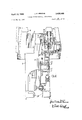
- FIGURE 4 is a section on the line 44 of FIGURE 2, with some parts removed,
- FIGURE 5 is a detail section on the line URE 2
- FIGURES 6 and 7 illustrate a manner of side-mounting the unit of FIGURES 1 to 5 in a concealed position
- FIGURE 8 is a View, corresponding to FIGURE 1, of a modified form of control unit,
- FIGURE 9 is a view in the direction of the arrow 9 of FIGURE 8, with the parts shown in the idle ahead setting instead of neutral,
- FIGURE 10 is a detail view in section on the line 10-10 of FIGURE 9, with parts removed,
- FIGURE 11 is a view in the direction of the arrow 11 of FIGURE 8, and
- FIGURE 12 is an elevation, desk-mounted double control unit of two engines.
- the control unit shown therein has a frame or housing 11, made up in two sections bolted together, with an upper part 12 of substantially rectangular form in plan surrounded by a horizontal flange 13.
- the flange enables the unit to be mounted on a control desk of a boat, with the greater part of the length of the frame 11 extending down below the desk through a rectangular hole cut therein, the level of the upper face of the desk being indicated at 14.
- the part of the frame 11 that stands above the desk 14, and the operative elements mounted thereon, are enclosed under a hood or cover 15 the lower edge of which seats on to the desk 14.
- a horizontal bearing sleeve 16 In which is journalled a hollow hub 19 that in turn forms a bearing for a control shaft 17 passing through the hub.
- This shaft projects out through an aperture in the wall of the hood 15 and its external end receives an upstanding control handle (not shown).
- the hub 19 is an integral part of a wheel 20 that lies beyond the inner end of the sleeve 16.
- the wheel 20 has teeth 21 at the lower portion of its periphery which mesh with a short toothed are 22 on a rotary clutch control member 23 that is journalled on a stub shaft 24 projecting from the frame 11.
- the clutch control member 23 has a pair of oppositely extending arms 25 and the core of a clutch control cable (not shown) is connected to one of these arms at 27.
- the cable extends down through the bottom end of the frame 11, the cable sheath being secured to a bottom bracket 29 of the frame.
- the inner end of the control shaft 17 carries a guide 30 that has a slot 31 through which passes a radial arm 32 slidable in the slot.
- the arm 32 is pivotally connected at 26 to a long depending link 34.
- a vertical fixed cam plate 35 having a cam slot 36 into which projects a pin 33 integral with the upper end of the arm 32.
- a plastic bush or roller 37 surrounds the pin 33 and acts as a follower in the cam slot.
- the lower end of the long link 34 is pivotally connected to the lower end of a second 5-5 of FIG- partly in section, of a for independent control 3 shorter link 38 and the pivot pin 39 is disposed to slide vertically in a central vertical slot 40 in the lower part of the frame 11.
- the stub shaft 24 is hollow and has journalled therein, concentrically with the clutch control member 23, the hub 41 of a rotary throttle control member 42.
- the throttle control member 42 has a pair of oppositely-extending arms 43 and to the end of one of these is connected, at 44, the core of a throttle control cable (not shown).
- the throttle cable passes out through the bottom end of the frame 11 and its sheath is secured to the bottom bracket 29.
- the upper end of the link 38 is pivotally connected to the arm 43, to which the throttle cable is connected, at a position intermediate the cable connection and the axis of rotation of the throttle control member 42.
- cam slot 36- in the fixed cam plate 35 has two arcuate side portions 46 which are struck about a centre coincident with the rotational axis of the control shaft 17, and these arcuate side portions are connected by a central top portion 47 which is substantially horizontal.
- the top portion 47 of the cam slot may in fact follow an arc of long radius struck abut a centre lying well down the vertical centre line 48 of the unit.
- the cable arm of the clutch control member 23 is substantially horizontal and the cable arm 43 of the throttle control member 42 is inclined upwardly as shown.
- the long link 34 is vertical, the cam follower 37 lying at the middle of the top portion 47 of the cam slot 36.
- the hub 19 of the wheel 20 is normally locked to the control shaft 17 by a locking pin 52 sliding in a radial bore 53 in the shaft and spring-urged outwardly into a hole 54 in the hub wall.
- a press button control is provided that depresses the pin 52 out of the hole 54 by means of a plunger 55.
- the plunger 55 is housed for vertical sliding in a side entry 57 of the sleeve 16 and it is operated by a spindle 56 that slides vertically in a bearing 58 in a top member of the frame 11.
- the spindle 56 passes up through the top of the hood 15 and has a press button on its upper end.
- the spindle is urged upwardly by a return spring 60. It will be observed that depression of the 4 pin 52 by the plunger 55 disconnects the hub 19 from the control shaft 17.
- the clutch and throttle control members, to which the cables are connected, are centrally pivot-mounted and double-armed simply for the convenience or enabling the cable connections to be made on either side, and to allow double-cable push-pull connections to be utilised if desired.
- two spring-pressed balls 50 are housed in pockets 51 in the frame on either side of the bearing sleeve 16 and bear against the wheel 20 which has three pairs of locating holes 70, 71, 72 cooperating with the balls. Not only do the balls 50 locate the wheel but they also take up backlash in the hub and shaft assembly 19, 17 and act as a damper in respect of throttle movement.
- the cable is received in a trunnion 73 which has a shank 75 fitting within a bush or insert 74 that is in turn received in a somewhat elongated aperture 76 in the arm 25.
- the shank 75 is retained in the insert 74 by means of pips 77 located in cooperating depressions; the aperture 76 has opposite sides that are toothed or serrated as at 78 which are engaged by the insert 74.
- the arrangement allows the trunnion shank to be adjusted to various places along the aperture 76.
- a clamp plate 79 is held to the arm 25 by a screw 80 and overlies the trunnion 73, a pip 81 on the outer end of the trunnion being located in a slot 82 in the clamp plate.
- a similar type of adjustment can also be provided for the throttle cable if desired, but is ordinarily not needed.
- Plastic thrust washers and bearing sleeves are used in the assembly, metal to metal contact being avoided.
- Molynylon bearing sleeves are shown provided at 83, 84 and 85.
- an adjustment of the throttle opening at idling speed can be provided by making the cam plate 35 adjustable vertically.
- the unit may be side mounted, in which case the flange 13 and a wall portion 86 of the frame 11, held in place by bolts 87 in the deskmounted version, are removed.
- FIGURES 6 and 7 illustrate how the unit modified in this Way can be side-mounted in a concealed position behind a panel 89.
- the panel has an aperture 90 through which the control shaft 17 projects and which is closed by a fascia plate 91 that has a re-entrant portion 92 to provide an inwardly-directed ledge 93 through which the control spindle 56 emerges.
- the shaft 17 and spindle 56 are passed through the appropriate openings in the plate 91 and the plate is secured to the frame 11 of the unit by means of screws 94.
- the main control handle 95 and the push botton 96 are fitted to the protruding portions of the shaft 17 and spindle 56, respectively.
- FIGURES 8 to 11 show a modification of the unit in which the cam plate and follower roller are no longer employed in the throttle control. Instead the radial arm 32, to which the long link 34 is pivotally connected, is now pinned to the end of the shaft 17, as at 88, to prevent it sliding and therefore operates simply as a crank. This means that during the clutch-shifting range of movement of the shaft 17 the engine throttle is opened slightly as forward or reverse drive is engaged but the movement is small because the link 34 is in the region of outer dead centre.
- the unit of FIGURES 8 to 11 is arranged as a surface side-mounting unit, in that the frame thereof is adapted for mounting on the external surface of a vertical panel. That is to say the frame 11A is now designed not only to provide a support for the other members of the assembly but also to serve as a cover, as shown.
- FIGURE 12 of the drawings shows a double control unit for independent control of two engines, arranged for desk mounting and operating in the same manner as the embodiment of FIGURES 1 to 5.
- a single lever control mechanism comprising; a housing, a main control shaft rotatably supported in said housing, a manual control handle attached to said control shaft for rotating said control shaft in either direction from a neutral position, a first control member rotatably supported by said housing, linkage means interconnecting said control shaft and said first control member for rotating said first control member always in the same direction when said control shaft is rotated in either direction from said neutral position, a second control member rotatably supported by said housing coaxially with said first control member, a drive member disposed on said control shaft and operatively engaging said second control member for rotating the latter, locking means normally locking said drive member to said control shaft whereby said drive member rotates with said control shaft, said locking means being movable to an unlocked position for allowing said first control member to be rotated independently of said second control member.
- said drive member comprises; a hub coaxially surrounding said main control shaft, a locking pin slidable in a radial bore in said main control shaft and projecting into a hole in said hub for normally locking said hub to said control shaft, and control means for moving said locking pin out of said hole in said hub, a spring biasing said locking pin against sliding movement by said control means.
- a mechanism as set forth in claim 1 including a first flexible transmission cable connected at one end to said first control member and adapted to be connected at the other end thereof to an engine throttle control, and a second flexible transmission cable connected at one end to said second control member and adapted to be connected at the other end to an engine clutch control.
- a mechanism as set forth in claim 4 including coupling means for adjusting the position of connection of said second cable to said second control member in a direction radially of the axis of rotation of said second control member.
- said linkage means includes a radial crank arm rotatable with said main control shaft and a first link pivotally connected at a first end to said crank arm and operatively connected at the second end to said first control member, said mechanism having a central axis, means confining movement of said second end of said first link to sliding movement parallel with said central axis, the longitudinal axis of said first link being parallel with said central axis when said main control shaft is in said neutral position.
- a mechanism as set forth in claim 7 including means mounting said crank arm for radial sliding movement relative to said main control shaft, a cam plate having a cam slot therein, and a cam follower disposed at the pivotal connection between said crank arm and said first link and guided by said cam slot.
- cam slot is symmetrical about said central axis of the mechanism and comprises two arcuate terminal portions joined by a substantially straight intermediate portion, said straight portion being at right angles to said central axis.
- a mechanism as set forth in claim 9 including a second link pivotally connected to said first control member at a position displaced from the axis of rotation of said first control member, said second end of said first link being pivotally connected to said second link.
Landscapes
- Engineering & Computer Science (AREA)
- Chemical & Material Sciences (AREA)
- Combustion & Propulsion (AREA)
- Mechanical Engineering (AREA)
- Ocean & Marine Engineering (AREA)
- Radar, Positioning & Navigation (AREA)
- Remote Sensing (AREA)
- Control Of Throttle Valves Provided In The Intake System Or In The Exhaust System (AREA)
Applications Claiming Priority (2)
| Application Number | Priority Date | Filing Date | Title |
|---|---|---|---|
| GB2109265 | 1965-05-18 | ||
| GB33018/65A GB1152182A (en) | 1965-05-18 | 1965-08-02 | Improvements in or relating to Single Handle Control Mechanisms |
Publications (1)
| Publication Number | Publication Date |
|---|---|
| US3438468A true US3438468A (en) | 1969-04-15 |
Family
ID=26255123
Family Applications (1)
| Application Number | Title | Priority Date | Filing Date |
|---|---|---|---|
| US557336A Expired - Lifetime US3438468A (en) | 1965-05-18 | 1966-05-18 | Single handle control mechanisms |
Country Status (2)
| Country | Link |
|---|---|
| US (1) | US3438468A (cs) |
| SE (1) | SE342597B (cs) |
Cited By (5)
| Publication number | Priority date | Publication date | Assignee | Title |
|---|---|---|---|---|
| US4253349A (en) * | 1979-03-05 | 1981-03-03 | Brunswick Corporation | Control unit for marine engines employing neutral lock mechanism |
| FR2582828A1 (fr) * | 1985-05-28 | 1986-12-05 | Outboard Marine Corp | Commande d'habitacle a manette unique |
| US5062516A (en) * | 1985-05-28 | 1991-11-05 | Outboard Marine Corporation | Single lever control |
| US5228548A (en) * | 1989-09-12 | 1993-07-20 | Ab Volvo Penta | Single lever control for boats |
| US5311968A (en) * | 1991-09-26 | 1994-05-17 | Baier & Koppel GmbH & Co., Prazisionsapparate | Progressive distributor for lubricants |
Citations (12)
| Publication number | Priority date | Publication date | Assignee | Title |
|---|---|---|---|---|
| US157765A (en) * | 1874-12-15 | Improvement in crank and piston connections for steam-engines | ||
| US739378A (en) * | 1902-06-05 | 1903-09-22 | Bliss E W Co | Drawing-press. |
| US2529182A (en) * | 1946-04-23 | 1950-11-07 | Erwin J Panish | Combined remote and proximal control device |
| US2804782A (en) * | 1955-06-20 | 1957-09-03 | Daimler Benz Ag | Control mechanism for a marine diesel engine |
| US2826283A (en) * | 1957-01-08 | 1958-03-11 | John F Morse | Engine control unit |
| US2847870A (en) * | 1956-07-20 | 1958-08-19 | Daimler Benz Ag | Apparatus for controlling the fuel supply and the reversing gear of a marine engine optionally by different control mechanisms |
| US2907421A (en) * | 1957-10-04 | 1959-10-06 | Morse Instr Company | Single lever engine control |
| US2966969A (en) * | 1958-08-05 | 1961-01-03 | John F Morse | Throttle operating mechanism for single lever control |
| US2987152A (en) * | 1958-09-08 | 1961-06-06 | John F Morse | Auxiliary throttle control for single lever control |
| US3018434A (en) * | 1957-10-29 | 1962-01-23 | Ite Circuit Breaker Ltd | Bar linkage for voltage compensated phase shifter |
| US3115050A (en) * | 1962-01-19 | 1963-12-24 | Marmac Products Inc | Control mechanism |
| US3204732A (en) * | 1963-09-03 | 1965-09-07 | John F Morse | Single lever control unit for clutch and throttle having a throttle dwell and an auxiliary throttle control |
-
1966
- 1966-05-17 SE SE6763/66A patent/SE342597B/xx unknown
- 1966-05-18 US US557336A patent/US3438468A/en not_active Expired - Lifetime
Patent Citations (12)
| Publication number | Priority date | Publication date | Assignee | Title |
|---|---|---|---|---|
| US157765A (en) * | 1874-12-15 | Improvement in crank and piston connections for steam-engines | ||
| US739378A (en) * | 1902-06-05 | 1903-09-22 | Bliss E W Co | Drawing-press. |
| US2529182A (en) * | 1946-04-23 | 1950-11-07 | Erwin J Panish | Combined remote and proximal control device |
| US2804782A (en) * | 1955-06-20 | 1957-09-03 | Daimler Benz Ag | Control mechanism for a marine diesel engine |
| US2847870A (en) * | 1956-07-20 | 1958-08-19 | Daimler Benz Ag | Apparatus for controlling the fuel supply and the reversing gear of a marine engine optionally by different control mechanisms |
| US2826283A (en) * | 1957-01-08 | 1958-03-11 | John F Morse | Engine control unit |
| US2907421A (en) * | 1957-10-04 | 1959-10-06 | Morse Instr Company | Single lever engine control |
| US3018434A (en) * | 1957-10-29 | 1962-01-23 | Ite Circuit Breaker Ltd | Bar linkage for voltage compensated phase shifter |
| US2966969A (en) * | 1958-08-05 | 1961-01-03 | John F Morse | Throttle operating mechanism for single lever control |
| US2987152A (en) * | 1958-09-08 | 1961-06-06 | John F Morse | Auxiliary throttle control for single lever control |
| US3115050A (en) * | 1962-01-19 | 1963-12-24 | Marmac Products Inc | Control mechanism |
| US3204732A (en) * | 1963-09-03 | 1965-09-07 | John F Morse | Single lever control unit for clutch and throttle having a throttle dwell and an auxiliary throttle control |
Cited By (5)
| Publication number | Priority date | Publication date | Assignee | Title |
|---|---|---|---|---|
| US4253349A (en) * | 1979-03-05 | 1981-03-03 | Brunswick Corporation | Control unit for marine engines employing neutral lock mechanism |
| FR2582828A1 (fr) * | 1985-05-28 | 1986-12-05 | Outboard Marine Corp | Commande d'habitacle a manette unique |
| US5062516A (en) * | 1985-05-28 | 1991-11-05 | Outboard Marine Corporation | Single lever control |
| US5228548A (en) * | 1989-09-12 | 1993-07-20 | Ab Volvo Penta | Single lever control for boats |
| US5311968A (en) * | 1991-09-26 | 1994-05-17 | Baier & Koppel GmbH & Co., Prazisionsapparate | Progressive distributor for lubricants |
Also Published As
| Publication number | Publication date |
|---|---|
| SE342597B (cs) | 1972-02-14 |
Similar Documents
| Publication | Publication Date | Title |
|---|---|---|
| US4119186A (en) | Single lever control having a throttle warm-up lever | |
| US4090598A (en) | Single lever remote control | |
| US4648497A (en) | Single lever control | |
| US3127785A (en) | Single lever engine and idle control | |
| JP3100973B2 (ja) | 舶用推進機の遠隔制御装置 | |
| US4222474A (en) | Single lever control with detent mechanism for holding lever vertically | |
| US3438468A (en) | Single handle control mechanisms | |
| US6238255B1 (en) | Marine propulsion control | |
| US4195534A (en) | Single lever remote control | |
| US3134269A (en) | Single lever control | |
| US3643528A (en) | Actuating handle assembly | |
| US2804782A (en) | Control mechanism for a marine diesel engine | |
| US4838822A (en) | Shift linkage for marine propulsion device | |
| US4027555A (en) | Engine transmission and speed control with warm-up interlock apparatus | |
| US2907421A (en) | Single lever engine control | |
| US2966969A (en) | Throttle operating mechanism for single lever control | |
| US3036476A (en) | Outboard engine control | |
| US3780842A (en) | Single clutch and throttle lever combined with a throttle warm up lever | |
| US2933943A (en) | Single lever operating controls | |
| US2987152A (en) | Auxiliary throttle control for single lever control | |
| US3581603A (en) | Marine engine control | |
| US2696188A (en) | Engine and reversing control for outboard motors | |
| US2919772A (en) | Throttle operating cam mechanism for single lever control | |
| US3301084A (en) | Single lever control system | |
| US2960199A (en) | Shifting arm for single lever engine control |