US342A - asher miller - Google Patents
asher miller Download PDFInfo
- Publication number
- US342A US342A US342DA US342A US 342 A US342 A US 342A US 342D A US342D A US 342DA US 342 A US342 A US 342A
- Authority
- US
- United States
- Prior art keywords
- steam
- piston
- pipe
- miller
- asher
- Prior art date
- Legal status (The legal status is an assumption and is not a legal conclusion. Google has not performed a legal analysis and makes no representation as to the accuracy of the status listed.)
- Expired - Lifetime
Links
- 239000011435 rock Substances 0.000 description 5
- 229910052799 carbon Inorganic materials 0.000 description 3
- 229910052717 sulfur Inorganic materials 0.000 description 3
- 238000010276 construction Methods 0.000 description 2
- 229910052698 phosphorus Inorganic materials 0.000 description 2
- 230000001105 regulatory effect Effects 0.000 description 2
- 229910052739 hydrogen Inorganic materials 0.000 description 1
- 239000000463 material Substances 0.000 description 1
- 239000002184 metal Substances 0.000 description 1
- 229910052751 metal Inorganic materials 0.000 description 1
- SNICXCGAKADSCV-UHFFFAOYSA-N nicotine Chemical compound CN1CCCC1C1=CC=CN=C1 SNICXCGAKADSCV-UHFFFAOYSA-N 0.000 description 1
- 229910052757 nitrogen Inorganic materials 0.000 description 1
- 238000004326 stimulated echo acquisition mode for imaging Methods 0.000 description 1
Images

Classifications
-
- F—MECHANICAL ENGINEERING; LIGHTING; HEATING; WEAPONS; BLASTING
- F01—MACHINES OR ENGINES IN GENERAL; ENGINE PLANTS IN GENERAL; STEAM ENGINES
- F01C—ROTARY-PISTON OR OSCILLATING-PISTON MACHINES OR ENGINES
- F01C1/00—Rotary-piston machines or engines
- F01C1/30—Rotary-piston machines or engines having the characteristics covered by two or more groups F01C1/02, F01C1/08, F01C1/22, F01C1/24 or having the characteristics covered by one of these groups together with some other type of movement between co-operating members
- F01C1/40—Rotary-piston machines or engines having the characteristics covered by two or more groups F01C1/02, F01C1/08, F01C1/22, F01C1/24 or having the characteristics covered by one of these groups together with some other type of movement between co-operating members having the movement defined in group F01C1/08 or F01C1/22 and having a hinged member
- F01C1/46—Rotary-piston machines or engines having the characteristics covered by two or more groups F01C1/02, F01C1/08, F01C1/22, F01C1/24 or having the characteristics covered by one of these groups together with some other type of movement between co-operating members having the movement defined in group F01C1/08 or F01C1/22 and having a hinged member with vanes hinged to the outer member
Definitions
- my invention consists in a revolving piston and in applying the steam thereto by means of a side pipe, eccentric or cam and shifting or slide valve as ordinarily applied to the reciprocating engine, thereby giving the piston a perfect rotary motion
- Figure 1 in the drawing'gives a perspective view of the external part at an angle of degrees on a scale of half the size of the model; that is to say, an inch on the scale of the model is equal to two inches:
- FIG. 2 gives an internal view of the engine.
- Figs. 3 and Flg. 5 repre- 4 represent detached parts. sents an edge view.
- Figs. 2, 3, 4 and 5 are on a scale of one fourth the size of the 5 X X and when raised fill the apertures W,
- Figs. 1 and 2 represent the frame; this'however is no partof thesuch metal and materials as are ordinarily used for the construction of steam engines.
- FIGs. 1 and 2 represent a circular steam pipe or side pipe terminating a little below and covering the apparatus WV, IV. This pipe may however be made to pass across the cylinder in a straight or curve line instead of going around the circumference as represented in those figures.
- D, D, D, D as seen in Figs. 1 and 2
- E, E as seen in all the figures, the axle or shaft
- F, F as seen in the Figs. 1 and 5 the eccentric, G, Gr, in Figs. 1 and 5, the eccentric rod, H, in Fig. 1, the
- S, S, S, in Fig. 2 represents the cylinder or groove in which the piston revolves.
- this cylinder or groove is represented when the wheel Q and piston P, are removed.
- T in Fig. 2 represents the shifting or slide valve which acts as in the reciprocate ing engine, alternately admitting the steam and permitting its escape according as the piston passes the valves R, R. UU, Fig. 2, a passage for the steam'in the side pipe, C, leading from the steam'chest D, through the apertures KW, into the cylinder, S.
- V, V, in Fig. 4 represents only an additional thickness on the inside of the case or box B, B, B, which merely gives strength to. the cylinder.
- X in Figs. 2 and 4 represents the rim or edges of the cylinder, case or box, which when matched together and united or fastened with bolts or screws form the inclosure of the cylinder or space S.
- ⁇ Vhen direction is given to it by the valve, R, and it is turned in the direction as denoted by the darts toward the piston P, and by pressure against it causes its revolution.
- the steam is let on and taken off alternately on the right and left which is regulated by the shifting or slide valve T, which is moved to the right and left by means of the eccentric, F, or a cam, the eccentric rod, G, the arm H, the rock shaft I, arm K, and rod L.
- the steam is let on and acts upon the piston, P, immediately after the piston passes the aperture, and continues to propel it during half its revolution until it passes the other aperture, W. lVhen the steam is shut oif and allowed to escape from this side as above described and let on through the other aperture and again from this side.
Landscapes
- Engineering & Computer Science (AREA)
- Mechanical Engineering (AREA)
- General Engineering & Computer Science (AREA)
- Transmission Devices (AREA)
Description
310F342. PATENTED Anew, 1837.
' A. MILLER.
ROTARY STEAM ENGINE.
UN ED sTArns ATENT OFFICE.
ASHER MILLER, OF LOOKPORT, NEW YORK.
' ROTARY STEAM-ENGINE.
Specification of Letters Patent No. 342, dated August 8, 1837.
To (ZZZ whom it may concern Be it known that I, ASHER MILLER, of the village of Lockport, in the county of Niagara and State of New York, have invented a new and useful Improvement in Steam- Engines; and I do hereby declare that the following is a full and exact description thereof.
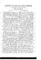
The nature of my invention consists in a revolving piston and in applying the steam thereto by means of a side pipe, eccentric or cam and shifting or slide valve as ordinarily applied to the reciprocating engine, thereby giving the piston a perfect rotary motion,
which may be constructed on either the high or low pressure principle. 7
Figure 1 in the drawing'gives a perspective view of the external part at an angle of degrees on a scale of half the size of the model; that is to say, an inch on the scale of the model is equal to two inches:
on the scale of the drawing. Fig. 2 gives an internal view of the engine. Figs. 3 and Flg. 5 repre- 4 represent detached parts. sents an edge view. Figs. 2, 3, 4 and 5 are on a scale of one fourth the size of the 5 X X and when raised fill the apertures W,
model.
To enable others skilled in the art to make and use my invention I will proceed to describe its construct-ion and operation.
A, A, A, as seen n Figs. 1 and 2 represent the frame; this'however is no partof thesuch metal and materials as are ordinarily used for the construction of steam engines.
C, C, C, in 'Figs. 1 and 2, represent a circular steam pipe or side pipe terminating a little below and covering the apparatus WV, IV. This pipe may however be made to pass across the cylinder in a straight or curve line instead of going around the circumference as represented in those figures.
D, D, D, as seen in Figs. 1 and 2, represent the steam chest; E, E, as seen in all the figures, the axle or shaft; F, F, as seen in the Figs. 1 and 5 the eccentric, G, Gr, in Figs. 1 and 5, the eccentric rod, H, in Fig. 1, the
arm on the rock shaft to which the eccentric 1s attached by means of a joint, I, in Fig. l, the rock shaft, K, on Figs. 1 and 2 an arm on the rock shaft to which-is attached the rod to the shiftingv or slide valve by means of a joint. L in Figs. 1 and 2, a rod to the shifting or slide valves with a joint near the center. M, M, in Figs. 1 and-2 stands which support the rock shaft. N, in Figs. 1 and 2, a steam pipe leading from the boiler to the steam chest. 0 in Figs. 1, and 2, an
exhaust pipe. P, in F igs. 2 and 3, the revolving piston permanently attached or aflixed to the wheelQ. Q, in Figs. 2 and 3, a wheel permanently attached to the axle, E, to which it gives motion. Every revolution of the wheel and piston will give one revolution of the axle or shaft. The piston willin all cases fillthe space S, (Fig. 2,)v in which itv revolves. R, R, in Fig. 2 the valves which give direction to the steam after it reaches and passes through the apertures W, W, as seen in Fig. 2. In this figure the darts show the direction of the steam acting onthis piston. These valves are sections of the circumference of the circle X W and complete the circle X X X, I
S, S, S, in Fig. 2, represents the cylinder or groove in which the piston revolves. In Fig. 4, this cylinder or groove is represented when the wheel Q and piston P, are removed.
T in Fig. 2, represents the shifting or slide valve which acts as in the reciprocate ing engine, alternately admitting the steam and permitting its escape according as the piston passes the valves R, R. UU, Fig. 2, a passage for the steam'in the side pipe, C, leading from the steam'chest D, through the apertures KW, into the cylinder, S.
V, V, in Fig. 4 represents only an additional thickness on the inside of the case or box B, B, B, which merely gives strength to. the cylinder.
X in Figs. 2 and 4, represents the rim or edges of the cylinder, case or box, which when matched together and united or fastened with bolts or screws form the inclosure of the cylinder or space S.
The following is a brief statement of the manner in which the steam is applied, and
of the motion and uses of the part-sz-The steam from the boiler passes through the steam pipe N (Figs. 1, and 2,) into the steam chest D; thence into the passage or pipe U (Fig. 2).
Its admission into this passage or pipe is regulated by .the shifting or slide valve T. This valve in Fig. 2, is shown at the extreme left hand side. When in this situation, the steam is permitted to enter the passage U, 011 the right hand side and prevented from entering that on the left hand side, while that steam which may be in the passage or pipe U, on the left hand side is permitted to escape through an opening in the bottom of this valve calculated for this purpose into the exhaust pipe. When this valve is changed to the right hand side the steam is let in on the left and let OH on the right hand side. From the pipe 01' passage, U, it passes through the aperture, W, into the cylinder or space S. \Vhen direction is given to it by the valve, R, and it is turned in the direction as denoted by the darts toward the piston P, and by pressure against it causes its revolution. The steam is let on and taken off alternately on the right and left which is regulated by the shifting or slide valve T, which is moved to the right and left by means of the eccentric, F, or a cam, the eccentric rod, G, the arm H, the rock shaft I, arm K, and rod L. Y The steam is let on and acts upon the piston, P, immediately after the piston passes the aperture, and continues to propel it during half its revolution until it passes the other aperture, W. lVhen the steam is shut oif and allowed to escape from this side as above described and let on through the other aperture and again from this side. propels the piston half a revolution. The revolution of this piston causes the revolution of the wheel Q, and axle or shaft, E; the piston being permanently attached to the wheel and the wheel to the axle or shaft. The revolution of the axle or shaft gives motion to the machinery in any mode desired. The valves, R, as rep resented in Fig. 2, on hinge valves which are raised up by the piston, P, in its passage under them, and close immediately after the passage of the piston. In that figure both valves, V, are represented as closed. I de' sign to construct them in such a manner as to move or slide them directly out so as to whereas in the reciprocating engine this And revolution is secondary or indirect. the inventor believes it will give more power with the same quantity of steam than any engine now in use. Another advantage gained over the common reciprocating engine is the continuous, constant and equal pressure of the steam upon the piston in one direction, thus avoiding those dead points at which in the common reciprocating engine foreign air is required to start it.
What I claim as my invention is- 'The combination of the shifting or slide valve with the rotary piston as seen in the accompanying model and in the drawings and as described in the above specification.
Dated Lockport July 22nd, 1837.
ASHER MILLER.
WVitnesses:
T. H. GHAPIN, NELSON ANGELL.
Publications (1)
| Publication Number | Publication Date |
|---|---|
| US342A true US342A (en) | 1837-08-08 |
Family
ID=2060621
Family Applications (1)
| Application Number | Title | Priority Date | Filing Date |
|---|---|---|---|
| US342D Expired - Lifetime US342A (en) | asher miller |
Country Status (1)
| Country | Link |
|---|---|
| US (1) | US342A (en) |
Cited By (1)
| Publication number | Priority date | Publication date | Assignee | Title |
|---|---|---|---|---|
| US5631437A (en) * | 1996-06-28 | 1997-05-20 | Techno-Sciences, Inc. | Gun muzzle control system using barrel mounted actuator assembly |
-
0
- US US342D patent/US342A/en not_active Expired - Lifetime
Cited By (1)
| Publication number | Priority date | Publication date | Assignee | Title |
|---|---|---|---|---|
| US5631437A (en) * | 1996-06-28 | 1997-05-20 | Techno-Sciences, Inc. | Gun muzzle control system using barrel mounted actuator assembly |
Similar Documents
| Publication | Publication Date | Title |
|---|---|---|
| US342A (en) | asher miller | |
| US658556A (en) | Rotary engine or motor. | |
| US67978A (en) | Melancthon hanford | |
| US143936A (en) | James c | |
| US465050A (en) | Steam-pump | |
| US811117A (en) | Valve for engines. | |
| US1013121A (en) | Fluid-operating mechanism. | |
| US444834A (en) | hayes | |
| US1084512A (en) | Multiple-power engine. | |
| US1219308A (en) | Rotary valve. | |
| US106078A (en) | Improvement in motive-power engines | |
| US306410A (en) | Steam-engine | |
| US42272A (en) | Improvement in the valve-gear of steam-engines | |
| US597274A (en) | Rotary engine | |
| US476868A (en) | Archibald i | |
| US46800A (en) | Improvement in steam-engines | |
| US847490A (en) | Steam-engine. | |
| US734944A (en) | Rotary engine. | |
| US223257A (en) | Rotary engine | |
| US40278A (en) | Improved rotary engine | |
| US659151A (en) | Rotary engine. | |
| US724261A (en) | Controlling mechanism for motors. | |
| US368974A (en) | Steam-engine | |
| US51565A (en) | Improvement in steam-engines | |
| US1254219A (en) | Engine. |