US3429514A - Bobbin changing device - Google Patents
Bobbin changing device Download PDFInfo
- Publication number
- US3429514A US3429514A US598259A US3429514DA US3429514A US 3429514 A US3429514 A US 3429514A US 598259 A US598259 A US 598259A US 3429514D A US3429514D A US 3429514DA US 3429514 A US3429514 A US 3429514A
- Authority
- US
- United States
- Prior art keywords
- bobbin
- yarn
- tube
- carrier
- arms
- Prior art date
- Legal status (The legal status is an assumption and is not a legal conclusion. Google has not performed a legal analysis and makes no representation as to the accuracy of the status listed.)
- Expired - Lifetime
Links
Images


Classifications
-
- B—PERFORMING OPERATIONS; TRANSPORTING
- B65—CONVEYING; PACKING; STORING; HANDLING THIN OR FILAMENTARY MATERIAL
- B65H—HANDLING THIN OR FILAMENTARY MATERIAL, e.g. SHEETS, WEBS, CABLES
- B65H67/00—Replacing or removing cores, receptacles, or completed packages at paying-out, winding, or depositing stations
- B65H67/04—Arrangements for removing completed take-up packages and or replacing by cores, formers, or empty receptacles at winding or depositing stations; Transferring material between adjacent full and empty take-up elements
-
- B—PERFORMING OPERATIONS; TRANSPORTING
- B65—CONVEYING; PACKING; STORING; HANDLING THIN OR FILAMENTARY MATERIAL
- B65H—HANDLING THIN OR FILAMENTARY MATERIAL, e.g. SHEETS, WEBS, CABLES
- B65H2701/00—Handled material; Storage means
- B65H2701/30—Handled filamentary material
- B65H2701/31—Textiles threads or artificial strands of filaments
Definitions
- An automatic bobbin changing device which comprises a movable carrier including means for releasably holding a. bobbin tube thereon on which a yarn is to be wound to form a bobbin.
- Actuating means is provided for moving the carrier to a first position in which the yarn is wound onto the bobbin tube, from there to intermediate position in which the fully wound bobbin is disengaged from the carrier, to a third position in which the carrier receives a first bobbin tube, and back to the first position.
- Winding means is provided for winding the yarn onto the bobbin tube when the carrier is in the first position, and operative means is provided for severing the yarn intermediate the winding means and the ejected bobbin in response to return movement of the carrier to the first position, and for attaching the leading end of the severed yarn to the empty bobbin tube held by the carrier.
- the present invention relates to bobbin changing devices.
- a more specific object of the invention is to provide such a bobbin changing device which is adapted for fully automated operation.
- An additional object of the invention is to provide an automatic bobbin changing device in which not only removal of the fully wound bobbin and replacement thereof by a new empty bobbin tube are automatically accomplished, but in which also the yarn is severed when such substitution takes place.
- a concomitant object of the invention is to provide such an automatic bobbin changing device in which the leading end of the thus-severed yarn is automatically attached to the new empty bobbin tube.
- an automatic bobbin changing device which comprises a movable carrier including means for releasably holding a bobbin tube thereon, and actuating means operatively connected with the carrier.
- the actuating means is provided for moving the carrier to a first position in which yarn is wound onto a bobbin tube held by the carrier to thereby form a bobbin, further to an intermediate position in which the fully wound bobbin is disengaged from the carrier, a third position in which the carrier receives a fresh empty bobbin tube, and back to the above-mentioned first position.
- Our novel automatic bobbin changing device further comprises winding means for winding yarn onto a bobbin tube held by the carrier when the latter is in the first position, and also operative means for severing the yarn intermediate the winding means and the ejected bobbin in response to the return movement of the carrier to its first position, and for attaching the leading end of thesevered yarn to the empty bobbin tube held by the carrier when the same returns to its first position.
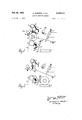
- FIG. 1 is a schematic view of a bobbin changing device in accordance with the present invention in one operative position thereof;
- FIG. 2 is a view similar to FIG. 1, but showing a bobbin changing device in a second operative position thereof;
- FIG. 3 is similar to the preceding figures and shows the bobbin changing device in a third operative position thereof.
- FIG. 4 shows diagrammatically the operative intercounection of the various elements of the novel bobbin changing device.
- the novel automatic bobbin changing device disclosed herein and shown in the figure comprises a pair of transversely spaced arms 1, only one of which is shown, which are pivotably mounted at their one end on a pivot 2 provided on a support 3, such as the frame of a winding machine.
- the other end of each arm 1 is provided with means for releasably holding a bobbin tube, such as a carrier 4, which is not shown in detail but may be constructed in accordance with the earlier mentioned copending application.
- the carriers 4 engage an elongated bobbin tube 5 onto which a yarn package 6 is wound.
- the winding of the yarn onto the tube 5 is accomplished by engagement of the tube 5 with a traversing roller 7, that is a roller which is capable of moving the yarn axially of the tube 5 from end to end thereof and thus traversing the yarn 8, which is nipped between the roller 7 and the tube 5.
- a traversing roller 7 that is a roller which is capable of moving the yarn axially of the tube 5 from end to end thereof and thus traversing the yarn 8, which is nipped between the roller 7 and the tube 5.
- the roller 7 engages no longer the tube 5 but the yarn package 6. In either case, however, the result is the same, namely that rotary motion is transmitted from the traversing roller 7, which is driven, to the non-driven tube 5 and the yarn package 6 thereon.
- both of the arms 1 are turnable about their respective pivots 2 between two extreme positions, and for this purpose an actuating arrangement 11 is provided which may be of any suitable type, many of which are known in the art.
- the arrangement 11 is a doubleacting pneumatic cylinder which is tiltably secured at a pivot 12 carried by a support, such as the machine frame 3.
- the piston rod of the arrangement 11 is hingedly connected at to the arms 1 so that, when the piston moves out of the arrangement 11, the arms and the yarn package and bobbin tube carried thereby will be moved in downward direction .as seen in the drawing, whereas when the piston 9 moves into the cylinder of the actuating arrangement 11, the arms will be lifted in upward direction.
- a feeding arrangement 13 for new empty bobbin tubes 5 Arranged upwardly of the arm 1 and, specifically, upwardly of the bobbin tube and yarn package carried by the arms 1, is a feeding arrangement 13 for new empty bobbin tubes 5.
- the arrangement 13 is provided with an outlet end and with a closing member 15 which is pivotable about an axis 16 and normally positioned by a biasing member, such as a spring 1'7, in such a manner that it will substantially close the outlet of the feed arrangement 13, and will prevent the empty bobbin tubes 5 from passing through the outlet.
- a wall portion 19 of the feed arrangement 13 is so shaped at the outlet end of the arrangement that one of the empty bobbin tubes 5 is always held in readiness to replace a fully wound bobbin.
- a chute 20 and a receptacle such as an intermittently operable conveyor 21.
- a nozzle 22 of an air supply pipe which can be opened and closed by a suitable valve arrangement, such as a solenoid valve, which in the presently illustrated embodiments is shown as operating a valve member which opens and closes the supply of air to the nozzle 22.
- a suitable valve arrangement such as a solenoid valve
- air is used for illustrative purposes only since many dilferent gases are suitable for the purpose which will be described below.
- the solenoid valve is identified with reference numeral 24 and it will be noted that it is operated by the arms 1 when the same contact a switch 25 of an electric circuit 29 connecting this switch with the solenoid valve.
- the limit switch 26 mentioned above is provided for the purpose of sensing the thickness of the yarn package 6 and it will be seen that it is connected via an electrical circuit 29a with the actuating device 11 or, more precisely, with a valve block which controls the admission of pressure fluid to the actuating device 11.
- the limit switch 26 senses that the yarn package 6 has reached 4 a determined thickness, it will actuate the valve block (which is shown in FIG. 4) so that fluid will be admitted into the actuating device 11, the piston 9 will be withdrawn, and the arms 1 thus lifted as seen in FIG. 1.
- the arms 1 continue to rise under the influence of the inwardly moving piston 9 of the actuating device 11 until they reach their third or extreme upper position in which the foremost one of the free empty tubes 5 in the feed arrangement 13 automatically becomes engaged between the free ends of the arms 1.
- the feeding arrangement 13 is open at its opposite lateral sides and since it is only as wide as the axial length of the tubes 5, that is of a lesser width than the spacing between the arms 1 so that the arms 1 can move upwardly beyond the plate member 15 and engage the foremost tube 5.
- the arms I When the arms I reach their lowermost position in which the new bobbin tube 5 engages the traversing roller 7 to be driven thereby, the arms actuate the limit switch 25 which, as pointed out earlier, is connected via an electrical circuit 29 with the solenoid valve 24.
- the limit switch 25 is also connected, however, with the valve block and thus automatically shuts off the supply of pressure fluid to the actuating device 11.
- the solenoid valve 24 activates the solenoid valve 24 so that the valve member 23 thereof is withdrawn from its position in which it closes the orifice 22 of the air supply pipe whereby a brief blast of air or other gas used in lieu of air is directed in upward direction as shown in FIG. 3.
- This air is sufiicient to lift the reserve length of yarn 8 upwardly in form of a loop 28 and to press it against the surface of the now rotating bobbin tube 5.
- the loop 28 is entrained by this engagement and is carried along by the rotating bobbin tube 5 towards the left as seen in FIG. 3 until it becomes caught between the tube 5 and the traversing roller 7.
- the yarn is broken and only new yarn 8 is henceforth wound onto the rotating bobbin tube 5 until a new yarn package 6 has come into existence and reaches its predetermined thickness, whereupon the process starts again.
- the device 28' is a conveyor which is arranged to carry away the fully wound bobbin shown in FIG. 2, then it is advantageous that this conveyor be intermittently operable so that it may stop while the replacement of the fully wound bobbin with a new bobbin tube, and the severing of the yarn, take place.
- this conveyor be intermittently operable so that it may stop while the replacement of the fully wound bobbin with a new bobbin tube, and the severing of the yarn, take place.
- this entire substitution operation goes forward, such an intermittent operation may not be necessary at all.
- An automatic bobbin changing device comprising, in combination, a movable carrier including means for releasably holding a bobbin tube thereon; actuating means operatively connected with said carrier for moving the same to a first position in which yarn is wound onto a bobbin tube held by the carrier to thereby form a bobbin, an intermediate position in which the fully wound bobbin is disengaged from said carrier, a third position in which said carrier receives a fresh empty bobbin tube, and back to said first position; winding means for winding yarn onto a bobbin tube held by said carrier when the latter is in said first position thereof; and operative means for severing the yarn intermediate said winding means and the ejected bobbin in response to return movement of said carrier to said first position thereof, and for attaching the leading end of the thus severed yarn to the empty bobbin tube held by said carrier.
- a device as defined in claim 2, wherein said feed comprises a chute in which said empty bobbin tubes are located, and having an outlet portion in which the foremost one of said empty bobbin tubes is held ready for engagement by said holding means on said carrier.
- said feed further comprising an ejecting portion extending into the path of movement of the fully wound bobbin when said carrier moves to said third position, to thereby disengage said bobbin from said carrier.
- a device as defined in claim 2 and further comprising detector means operatively connected with said actuating means and arranged to scan the bobbin on said carrier in said first position of the latter for operating said actuating means when the diameter of said bobbin increases to a predetermined extent.
- said actuating means includes a cylinder and a double-acting piston reciprocable therein.
- a device as defined in claim 1 and further comprising sensor means arranged to be activated by said carrier when the same is in said third position, and operatively connected with said actuating means for actuating the same and initiating return movement of said carrier to said first position.
Description
Feb. 25, 1969 Filed Dec. 1. 1966 V INVENTORS fYUQ't/K 'J I n s)? Feb. 25, 1969 Filed Dec. 1. 1966 F. pos flL ETAL 3,429,514
BOBBIN CHANGING DEVICE Sheet 2 of 3 Sheet Filed Dec. 1. 1966 vmock '2 gay SOLE/VOID VALVE COMPRESSOR v FLU/D cowu/r 1 WW1 y United States Patent Claims ABSTRACT OF THE DISCLOSURE An automatic bobbin changing device which comprises a movable carrier including means for releasably holding a. bobbin tube thereon on which a yarn is to be wound to form a bobbin. Actuating means is provided for moving the carrier to a first position in which the yarn is wound onto the bobbin tube, from there to intermediate position in which the fully wound bobbin is disengaged from the carrier, to a third position in which the carrier receives a first bobbin tube, and back to the first position. Winding means is provided for winding the yarn onto the bobbin tube when the carrier is in the first position, and operative means is provided for severing the yarn intermediate the winding means and the ejected bobbin in response to return movement of the carrier to the first position, and for attaching the leading end of the severed yarn to the empty bobbin tube held by the carrier.
Cross-references to related applications A elampin g device for releasably holding a bobbin tube, suitable for use on the movable carrier of the hereindisclosed automatic bobbin changing device, is disclosed in our copending application entitled, Clamping Device, filed on Dec. 1, 1966, Ser. No. 598,356.
Background of the invention The present invention relates to bobbin changing devices.
In the yarn producing industry high-speed automatic machines manufacture yarn at a high hourly rate of output. It is not usually possible to store the yarn as it leaves the machines and it is, therefore, customary to wind the yarn immediately onto bobbins for storage and transport. This is particularly true of bobbins in cross-winding rnachines and in machines for spindleless spinning from slivers. However, contrary to the remainder of the yarnproducing machines, the operation of the bobbin winding machines heretofore has not been fully automated since no constructions have become known in which the fully wound bobbin is removed from the winding machine automatically and equally automatically replaced with an empty bobbin tube onto which new material is wound to form another bobbin. Consequently, it is still customary at this time to doff the fully wound bobbins manually, particularly in cross-winding machines and in machines for the spindleless spinning from slivers, and similarly to place the empty bobbin tubes in position by hand. This is very time-consuming and defeats entirely the purposes of automation through which economies can be achieved only if all cooperating parts of an installation are automated.
There is known a semi-automatic device by means of which the bobbin exchange is capable of being effected. However, semi-automatic operation is neither fast enough nor reliable enough and it is an additional disadvantage of this prior art construction that the bobbins and/or the empty bobbin tubes are not positively held by the device.
It has, therefore, long been the desire of industry to 3,429,514 Patented Feb. 25, 1969 have available a fully automatic bobbin changing device, but heretofore such a device has not been in existence to our knowledge.
Summary of the invention It is, therefore, a general object of the present invention to provide a bobbin changing device which is not possessed of the disadvantages set forth above.
A more specific object of the invention is to provide such a bobbin changing device which is adapted for fully automated operation.
An additional object of the invention is to provide an automatic bobbin changing device in which not only removal of the fully wound bobbin and replacement thereof by a new empty bobbin tube are automatically accomplished, but in which also the yarn is severed when such substitution takes place.
A concomitant object of the invention is to provide such an automatic bobbin changing device in which the leading end of the thus-severed yarn is automatically attached to the new empty bobbin tube.
In accordance with one feature of our invention we provide an automatic bobbin changing device which comprises a movable carrier including means for releasably holding a bobbin tube thereon, and actuating means operatively connected with the carrier. The actuating means is provided for moving the carrier to a first position in which yarn is wound onto a bobbin tube held by the carrier to thereby form a bobbin, further to an intermediate position in which the fully wound bobbin is disengaged from the carrier, a third position in which the carrier receives a fresh empty bobbin tube, and back to the above-mentioned first position. Our novel automatic bobbin changing device further comprises winding means for winding yarn onto a bobbin tube held by the carrier when the latter is in the first position, and also operative means for severing the yarn intermediate the winding means and the ejected bobbin in response to the return movement of the carrier to its first position, and for attaching the leading end of thesevered yarn to the empty bobbin tube held by the carrier when the same returns to its first position.
The novel features which are considered as characteristic for the invention are set forth in particular in the appended claims. The invention itself, however, both as to its construction and its method of operation, together with additional objects and advantages thereof, will be best understood from the following description of specific embodiments when read in connection with the accompanying drawing.
Brief description of the drawing FIG. 1 is a schematic view of a bobbin changing device in accordance with the present invention in one operative position thereof;
FIG. 2 is a view similar to FIG. 1, but showing a bobbin changing device in a second operative position thereof;
FIG. 3 is similar to the preceding figures and shows the bobbin changing device in a third operative position thereof; and
FIG. 4 shows diagrammatically the operative intercounection of the various elements of the novel bobbin changing device.
Description of the preferred embodiments Discussing now the drawing in detail, and firstly FIG. 1 thereof, it will be seen that the novel automatic bobbin changing device disclosed herein and shown in the figure comprises a pair of transversely spaced arms 1, only one of which is shown, which are pivotably mounted at their one end on a pivot 2 provided on a support 3, such as the frame of a winding machine. The other end of each arm 1 is provided with means for releasably holding a bobbin tube, such as a carrier 4, which is not shown in detail but may be constructed in accordance with the earlier mentioned copending application. The carriers 4 engage an elongated bobbin tube 5 onto which a yarn package 6 is wound. The winding of the yarn onto the tube 5 is accomplished by engagement of the tube 5 with a traversing roller 7, that is a roller which is capable of moving the yarn axially of the tube 5 from end to end thereof and thus traversing the yarn 8, which is nipped between the roller 7 and the tube 5. Of course, as yarn becomes wound onto the tube 5, and the yarn package 6 develops, the roller 7 engages no longer the tube 5 but the yarn package 6. In either case, however, the result is the same, namely that rotary motion is transmitted from the traversing roller 7, which is driven, to the non-driven tube 5 and the yarn package 6 thereon.
As is clearly evident from FIG. 1, both of the arms 1 are turnable about their respective pivots 2 between two extreme positions, and for this purpose an actuating arrangement 11 is provided which may be of any suitable type, many of which are known in the art. In the present instance it is assumed that the arrangement 11 is a doubleacting pneumatic cylinder which is tiltably secured at a pivot 12 carried by a support, such as the machine frame 3. The piston rod of the arrangement 11 is hingedly connected at to the arms 1 so that, when the piston moves out of the arrangement 11, the arms and the yarn package and bobbin tube carried thereby will be moved in downward direction .as seen in the drawing, whereas when the piston 9 moves into the cylinder of the actuating arrangement 11, the arms will be lifted in upward direction.
It will also be evident that, as the thickness of the yarn package 6 on the bobbin tube 5 increases, the arms 1 will be lifted in upward direction until the surface of the yarn package engages a sensor which is here shown as a limit switch 26 and whose purpose will be explained below.
Arranged upwardly of the arm 1 and, specifically, upwardly of the bobbin tube and yarn package carried by the arms 1, is a feeding arrangement 13 for new empty bobbin tubes 5. The arrangement 13 is provided with an outlet end and with a closing member 15 which is pivotable about an axis 16 and normally positioned by a biasing member, such as a spring 1'7, in such a manner that it will substantially close the outlet of the feed arrangement 13, and will prevent the empty bobbin tubes 5 from passing through the outlet. It will be noted that a wall portion 19 of the feed arrangement 13 is so shaped at the outlet end of the arrangement that one of the empty bobbin tubes 5 is always held in readiness to replace a fully wound bobbin.
Located below a tangent line common to both the clamped bobbin tube 5 carried by the arms 1 and the traverse roller 7 there is provided a chute 20 and a receptacle, such as an intermittently operable conveyor 21. Located adjacent the chute 20 and the traverse roller 7 is a nozzle 22 of an air supply pipe which can be opened and closed by a suitable valve arrangement, such as a solenoid valve, which in the presently illustrated embodiments is shown as operating a valve member which opens and closes the supply of air to the nozzle 22. Of course, the term air is used for illustrative purposes only since many dilferent gases are suitable for the purpose which will be described below. The solenoid valve is identified with reference numeral 24 and it will be noted that it is operated by the arms 1 when the same contact a switch 25 of an electric circuit 29 connecting this switch with the solenoid valve.
The limit switch 26 mentioned above is provided for the purpose of sensing the thickness of the yarn package 6 and it will be seen that it is connected via an electrical circuit 29a with the actuating device 11 or, more precisely, with a valve block which controls the admission of pressure fluid to the actuating device 11. Thus, when the limit switch 26 senses that the yarn package 6 has reached 4 a determined thickness, it will actuate the valve block (which is shown in FIG. 4) so that fluid will be admitted into the actuating device 11, the piston 9 will be withdrawn, and the arms 1 thus lifted as seen in FIG. 1.
The inward movement of piston 9 continues, and thus the arms 11 also continue to rise until the fully wound bobbin consisting of the bobbin tube 5 and the yarn package 6 thereon strikes the plate member 15 of the bobbin tube feeding arrangement 13 and is thus dislodged or ejected from its position between the free ends of the arms 1. The bobbin thus falls onto the chute 20 and is conveyed thereby onto the receptacle or conveyor 21 which, it will be understood, may be intermittently movable. The yarn 8 extending across the traverse roller 7 remains unsevered and extends from the traverse roller 7 to the bobbin which is now located, as shown in FIG. 2, on the conveyor 21. Thus, a reserve length of yarn is formed between the traverse roller 7 and the yarn package 6 on the conveyor 21.
As is evident in FIG. 2 the arms 1 continue to rise under the influence of the inwardly moving piston 9 of the actuating device 11 until they reach their third or extreme upper position in which the foremost one of the free empty tubes 5 in the feed arrangement 13 automatically becomes engaged between the free ends of the arms 1. This is possible since the feeding arrangement 13 is open at its opposite lateral sides and since it is only as wide as the axial length of the tubes 5, that is of a lesser width than the spacing between the arms 1 so that the arms 1 can move upwardly beyond the plate member 15 and engage the foremost tube 5. When the arms I reach this position in which they engage this foremost tube 5, they also actuate another limit switch 27 which is connected via an electrical circuit 29b with the valve block and which thus changes the flow of pressure fluid into the device 11 to reverse the movement of the piston 9 which now travels in downward direction. The arms 11 with their new free bobbin tube 5 thus begin to descend in the direction toward the traversing roller 7 until the new tube 5 abuts against the traversing roller 7 and is rotated thereby. It is evident from FIG. 2 that during such downward movement the pressure of the foremost tube 5 against the upwardly biased plate member 15 is suflicient to deflect the latter in downward direction so that the foremost tube 5 held by the arms 1 can move out of the feeding arrangement 13 whereas, once the tube has moved beyond the plate member 15, the latter will snap back into place and prevent the other tubes 5 in the feeding arrangement 13 from falling out.
When the arms I reach their lowermost position in which the new bobbin tube 5 engages the traversing roller 7 to be driven thereby, the arms actuate the limit switch 25 which, as pointed out earlier, is connected via an electrical circuit 29 with the solenoid valve 24. The limit switch 25 is also connected, however, with the valve block and thus automatically shuts off the supply of pressure fluid to the actuating device 11. At the same time it activates the solenoid valve 24 so that the valve member 23 thereof is withdrawn from its position in which it closes the orifice 22 of the air supply pipe whereby a brief blast of air or other gas used in lieu of air is directed in upward direction as shown in FIG. 3. This air is sufiicient to lift the reserve length of yarn 8 upwardly in form of a loop 28 and to press it against the surface of the now rotating bobbin tube 5. The loop 28 is entrained by this engagement and is carried along by the rotating bobbin tube 5 towards the left as seen in FIG. 3 until it becomes caught between the tube 5 and the traversing roller 7. When this takes place the yarn is broken and only new yarn 8 is henceforth wound onto the rotating bobbin tube 5 until a new yarn package 6 has come into existence and reaches its predetermined thickness, whereupon the process starts again.
It has been pointed out before if the device 28' is a conveyor which is arranged to carry away the fully wound bobbin shown in FIG. 2, then it is advantageous that this conveyor be intermittently operable so that it may stop while the replacement of the fully wound bobbin with a new bobbin tube, and the severing of the yarn, take place. Of course, depending on the speed with which this entire substitution operation goes forward, such an intermittent operation may not be necessary at all.
The diagrammatic illustration of the various connections between the interrelated elements of the automatic bobbin changing device in accordance with the present invention, as illustrated in FIG. 4, is believed to be selfexplanatory.
It will be understood that each of the elements described above, or two or more together, may also find a useful application in other types of bobbin changing devices differing from the types described above.
While the invention has been illustrated and described as embodied in a bobbin changing device, it is not intended to be limited to the details shown, since various modifications and structural changes may be made without departing in any way from the spirit of the present invention.
Without further analysis, the foregoing will so fully reveal the gist of the present invention that others can by applying current knowledge readily adapt it for various applications without omitting features that, from the standpoint of prior art, fairly constitute essential characteristics of the generic or specific aspects of this invention and, therefore, such adaptations should and are intended to be comprehended Within the meaning and range of equivalence of the following claims.
What is claimed as new and desired to be protected by Letters Patent is set forth in the appended claims:
1. An automatic bobbin changing device comprising, in combination, a movable carrier including means for releasably holding a bobbin tube thereon; actuating means operatively connected with said carrier for moving the same to a first position in which yarn is wound onto a bobbin tube held by the carrier to thereby form a bobbin, an intermediate position in which the fully wound bobbin is disengaged from said carrier, a third position in which said carrier receives a fresh empty bobbin tube, and back to said first position; winding means for winding yarn onto a bobbin tube held by said carrier when the latter is in said first position thereof; and operative means for severing the yarn intermediate said winding means and the ejected bobbin in response to return movement of said carrier to said first position thereof, and for attaching the leading end of the thus severed yarn to the empty bobbin tube held by said carrier.
2. A device as defined in claim 1, and further comprising a feed for supplying empty bobbin tubes to said carrier in said third position thereof.
3. A device as defined in claim 2, wherein said feed comprises a chute in which said empty bobbin tubes are located, and having an outlet portion in which the foremost one of said empty bobbin tubes is held ready for engagement by said holding means on said carrier.
4. A device as defined in claim 3, said feed further comprising an ejecting portion extending into the path of movement of the fully wound bobbin when said carrier moves to said third position, to thereby disengage said bobbin from said carrier.
5. A device as defined in claim 2, and further comprising detector means operatively connected with said actuating means and arranged to scan the bobbin on said carrier in said first position of the latter for operating said actuating means when the diameter of said bobbin increases to a predetermined extent.
6. A device as defined in claim 5, further comprising support means for the disengaged bobbin spaced from said yarn winding means, said operative means comprising a nozzle including at least one orifice arranged intermediate said yarn winding means and said support means, a source of compressed fluid connected with said nozzle for supplying a gas thereto, and valve means manually sealing said nozzle from said source and arranged to permit flow of fluid from said source to said nozzle in response to return movement of said carrier to said first position so that a length of yarn extending intermediate said yarn winding means and said disengaged bobbin is lifted by gas from said nozzle and entrained around said fresh bobbin tube.
7. A device as defined in claim 6, wherein said winding means cooperates with said fresh bobbin tube for rotating the same, and wherein the yarn length entrained by the the rotating bobbin tube is carried between the latter and said Winding means and breaks automatically in response to continued rotation of said bobbin tube.
8. A device as defined in claim 1, wherein said actuating means includes a cylinder and a double-acting piston reciprocable therein.
9. A device as defined in claim 8, wherein said carrier comprises a pair of spaced parallel arms, and wherein said piston is articulately connected to at least one of said arms.
10. A device as defined in claim 1, and further comprising sensor means arranged to be activated by said carrier when the same is in said third position, and operatively connected with said actuating means for actuating the same and initiating return movement of said carrier to said first position.
References Cited UNITED STATES PATENTS 1,949,997 3/1934 Fourness 242-- 2,385,692 9/ 1945 Corbin et al. 24265 X 2,520,826 8/1950 Beck 242-65 2,905,402 9/1959 Foller et al. 242-18 3,160,359 12/1964 Furst 242-355 STANLEY N. GILREATH, Primary Examiner.
Applications Claiming Priority (1)
| Application Number | Priority Date | Filing Date | Title |
|---|---|---|---|
| CS719065 | 1965-12-01 |
Publications (1)
| Publication Number | Publication Date |
|---|---|
| US3429514A true US3429514A (en) | 1969-02-25 |
Family
ID=5420570
Family Applications (1)
| Application Number | Title | Priority Date | Filing Date |
|---|---|---|---|
| US598259A Expired - Lifetime US3429514A (en) | 1965-12-01 | 1966-12-01 | Bobbin changing device |
Country Status (6)
| Country | Link |
|---|---|
| US (1) | US3429514A (en) |
| AT (1) | AT273742B (en) |
| CH (1) | CH468302A (en) |
| DE (1) | DE1560628A1 (en) |
| FR (1) | FR1504856A (en) |
| GB (1) | GB1166504A (en) |
Cited By (15)
| Publication number | Priority date | Publication date | Assignee | Title |
|---|---|---|---|---|
| US3512726A (en) * | 1967-02-01 | 1970-05-19 | Mann Maschf Chr | Apparatus for changing winding-up bobbins on drawing frames and preparatory spinning machines |
| US3532278A (en) * | 1968-10-31 | 1970-10-06 | Du Pont | Yarn winding apparatus |
| US3572597A (en) * | 1966-11-07 | 1971-03-30 | Scragg & Sons | Textile machines |
| US3682403A (en) * | 1970-05-01 | 1972-08-08 | Logan Inc Jonathan | Apparatus and method for doffing wound packages and donning empty cores |
| US3741490A (en) * | 1971-11-16 | 1973-06-26 | Logan J | Yarn package doffing apparatus and method |
| US3801030A (en) * | 1970-06-30 | 1974-04-02 | Asahi Chemical Ind | Yarn winding process and a machine adapted for carrying out same |
| US3921922A (en) * | 1969-10-03 | 1975-11-25 | Rieter Ag Maschf | Method of automatically changing winding tubes and winding apparatus for implementing the aforesaid method and improved spool doffing mechanism |
| US3940076A (en) * | 1973-04-16 | 1976-02-24 | Daiwa Boseki Kabushiki Kaisha | Apparatus for handling a yarn end during a donning operation on a textile machine |
| US3942731A (en) * | 1972-07-06 | 1976-03-09 | Rieter Machine Works, Ltd. | Method and apparatus for forming reserve windings during a bobbin change on a spinning machine |
| US4054250A (en) * | 1975-04-11 | 1977-10-18 | N. Schlumberger & Cie | Textile winding machine |
| US4550880A (en) * | 1984-04-06 | 1985-11-05 | Belmont Textile Machinery Company | Method and apparatus for detecting the position of a take-up package during an automatic doffing and donning cycle |
| US4591105A (en) * | 1984-04-06 | 1986-05-27 | Belmont Textile Machinery Company | Method and apparatus for automatically doffing and donning take-up packages on a winder |
| USRE33111E (en) * | 1984-04-06 | 1989-11-14 | Belmont Textile Machinery Company | Method and apparatus for automatically doffing and donning take-up packages on a winder |
| US5246178A (en) * | 1989-12-12 | 1993-09-21 | Savio S.P.A. | Device for anchoring thread to the surface of a winding bobbin |
| CN112919255A (en) * | 2021-01-25 | 2021-06-08 | 国网浙江嘉善县供电有限公司 | Coiling machine convenient to unload |
Families Citing this family (1)
| Publication number | Priority date | Publication date | Assignee | Title |
|---|---|---|---|---|
| DE2506362C2 (en) * | 1975-02-14 | 1992-01-02 | Stahlecker, Fritz, 7347 Bad Überkingen | Open-end spinning machine |
Citations (5)
| Publication number | Priority date | Publication date | Assignee | Title |
|---|---|---|---|---|
| US1949997A (en) * | 1931-11-16 | 1934-03-06 | Paper Patents Co | Paper winder |
| US2385692A (en) * | 1942-04-07 | 1945-09-25 | Scott Paper Co | Continuous winding machine |
| US2520826A (en) * | 1945-12-29 | 1950-08-29 | Marcalus Mfg Company Inc | Means for preventing deformation of tubular cores |
| US2905402A (en) * | 1955-01-19 | 1959-09-22 | Glanzstoff Ag | Bobbin changing apparatus |
| US3160359A (en) * | 1962-05-19 | 1964-12-08 | Reiners Walter | Yarn-spool winding machine |
-
1966
- 1966-03-01 AT AT192566A patent/AT273742B/en active
- 1966-11-09 DE DE19661560628 patent/DE1560628A1/en active Pending
- 1966-11-09 CH CH1613666A patent/CH468302A/en unknown
- 1966-11-16 GB GB51281/66A patent/GB1166504A/en not_active Expired
- 1966-11-22 FR FR84512A patent/FR1504856A/en not_active Expired
- 1966-12-01 US US598259A patent/US3429514A/en not_active Expired - Lifetime
Patent Citations (5)
| Publication number | Priority date | Publication date | Assignee | Title |
|---|---|---|---|---|
| US1949997A (en) * | 1931-11-16 | 1934-03-06 | Paper Patents Co | Paper winder |
| US2385692A (en) * | 1942-04-07 | 1945-09-25 | Scott Paper Co | Continuous winding machine |
| US2520826A (en) * | 1945-12-29 | 1950-08-29 | Marcalus Mfg Company Inc | Means for preventing deformation of tubular cores |
| US2905402A (en) * | 1955-01-19 | 1959-09-22 | Glanzstoff Ag | Bobbin changing apparatus |
| US3160359A (en) * | 1962-05-19 | 1964-12-08 | Reiners Walter | Yarn-spool winding machine |
Cited By (15)
| Publication number | Priority date | Publication date | Assignee | Title |
|---|---|---|---|---|
| US3572597A (en) * | 1966-11-07 | 1971-03-30 | Scragg & Sons | Textile machines |
| US3512726A (en) * | 1967-02-01 | 1970-05-19 | Mann Maschf Chr | Apparatus for changing winding-up bobbins on drawing frames and preparatory spinning machines |
| US3532278A (en) * | 1968-10-31 | 1970-10-06 | Du Pont | Yarn winding apparatus |
| US3921922A (en) * | 1969-10-03 | 1975-11-25 | Rieter Ag Maschf | Method of automatically changing winding tubes and winding apparatus for implementing the aforesaid method and improved spool doffing mechanism |
| US3682403A (en) * | 1970-05-01 | 1972-08-08 | Logan Inc Jonathan | Apparatus and method for doffing wound packages and donning empty cores |
| US3801030A (en) * | 1970-06-30 | 1974-04-02 | Asahi Chemical Ind | Yarn winding process and a machine adapted for carrying out same |
| US3741490A (en) * | 1971-11-16 | 1973-06-26 | Logan J | Yarn package doffing apparatus and method |
| US3942731A (en) * | 1972-07-06 | 1976-03-09 | Rieter Machine Works, Ltd. | Method and apparatus for forming reserve windings during a bobbin change on a spinning machine |
| US3940076A (en) * | 1973-04-16 | 1976-02-24 | Daiwa Boseki Kabushiki Kaisha | Apparatus for handling a yarn end during a donning operation on a textile machine |
| US4054250A (en) * | 1975-04-11 | 1977-10-18 | N. Schlumberger & Cie | Textile winding machine |
| US4550880A (en) * | 1984-04-06 | 1985-11-05 | Belmont Textile Machinery Company | Method and apparatus for detecting the position of a take-up package during an automatic doffing and donning cycle |
| US4591105A (en) * | 1984-04-06 | 1986-05-27 | Belmont Textile Machinery Company | Method and apparatus for automatically doffing and donning take-up packages on a winder |
| USRE33111E (en) * | 1984-04-06 | 1989-11-14 | Belmont Textile Machinery Company | Method and apparatus for automatically doffing and donning take-up packages on a winder |
| US5246178A (en) * | 1989-12-12 | 1993-09-21 | Savio S.P.A. | Device for anchoring thread to the surface of a winding bobbin |
| CN112919255A (en) * | 2021-01-25 | 2021-06-08 | 国网浙江嘉善县供电有限公司 | Coiling machine convenient to unload |
Also Published As
| Publication number | Publication date |
|---|---|
| FR1504856A (en) | 1967-12-08 |
| AT273742B (en) | 1969-08-25 |
| GB1166504A (en) | 1969-10-08 |
| CH468302A (en) | 1969-02-15 |
| DE1560628A1 (en) | 1971-03-25 |
Similar Documents
| Publication | Publication Date | Title |
|---|---|---|
| US3429514A (en) | Bobbin changing device | |
| US3295775A (en) | Method and apparatus for readying the winding operation of yarn supply coils on coil winding machines | |
| US3695017A (en) | Automatic yarn piecing apparatus for spindleless spinning machine | |
| US3820730A (en) | Automatic doffing apparatus for textile machine having one or more winding units | |
| US2789774A (en) | Textile winding | |
| US3774859A (en) | Bobbin handling system | |
| US5484116A (en) | Method and apparatus for moving individual yarn ends into a yarn end joining device | |
| CN101596990B (en) | Suction nozzle | |
| US3092340A (en) | Yarn-package winding machine | |
| US3901456A (en) | Automatic winding machine | |
| ITMI951231A1 (en) | APPARATUS FOR SUPPLYING THE WIRE WINDING SPINDLES IN A CHANNEL | |
| US2786315A (en) | Means for filling a collector with fiber-wound bobbins | |
| US4674636A (en) | Bobbin removing apparatus | |
| US3599886A (en) | Automatic winder | |
| US3224692A (en) | Transfer tail winding apparatus | |
| US3160359A (en) | Yarn-spool winding machine | |
| US5374000A (en) | Cop changing mechanism for a winding unit | |
| JP2019031399A (en) | Device for clearing removal of yarn defects from yarn | |
| US3049231A (en) | Bobbin sorter | |
| US3370798A (en) | Centerless winder | |
| US3031149A (en) | Method and means for readying a yarn coil to be unwound | |
| US3920193A (en) | Winding apparatus with automatic changing of tubes or the like | |
| US3305087A (en) | Apparatus for sorting yarn-coil cores with and without yarn remainders | |
| US4558776A (en) | Apparatus for arranging cross-wound packages on an auxiliary transport belt | |
| US4002305A (en) | Device for forming a tail wind around a bobbin held by a take-up mechanism of a ringless spinning machine |