US3402672A - Roller pump assembly - Google Patents
Roller pump assembly Download PDFInfo
- Publication number
- US3402672A US3402672A US544135A US54413566A US3402672A US 3402672 A US3402672 A US 3402672A US 544135 A US544135 A US 544135A US 54413566 A US54413566 A US 54413566A US 3402672 A US3402672 A US 3402672A
- Authority
- US
- United States
- Prior art keywords
- rotor
- roller
- pump
- fluid
- slot
- Prior art date
- Legal status (The legal status is an assumption and is not a legal conclusion. Google has not performed a legal analysis and makes no representation as to the accuracy of the status listed.)
- Expired - Lifetime
Links
- 239000012530 fluid Substances 0.000 description 26
- 238000005086 pumping Methods 0.000 description 17
- 230000000712 assembly Effects 0.000 description 4
- 238000000429 assembly Methods 0.000 description 4
- 239000007788 liquid Substances 0.000 description 4
- 238000004891 communication Methods 0.000 description 3
- 230000004048 modification Effects 0.000 description 3
- 238000012986 modification Methods 0.000 description 3
- 230000004323 axial length Effects 0.000 description 2
- 230000000994 depressogenic effect Effects 0.000 description 2
- 230000002093 peripheral effect Effects 0.000 description 2
- 230000000295 complement effect Effects 0.000 description 1
- 230000008878 coupling Effects 0.000 description 1
- 238000010168 coupling process Methods 0.000 description 1
- 238000005859 coupling reaction Methods 0.000 description 1
- 230000003467 diminishing effect Effects 0.000 description 1
- 238000006073 displacement reaction Methods 0.000 description 1
- 238000004519 manufacturing process Methods 0.000 description 1
- 239000000463 material Substances 0.000 description 1
- 238000007789 sealing Methods 0.000 description 1
Images
Classifications
-
- F—MECHANICAL ENGINEERING; LIGHTING; HEATING; WEAPONS; BLASTING
- F04—POSITIVE - DISPLACEMENT MACHINES FOR LIQUIDS; PUMPS FOR LIQUIDS OR ELASTIC FLUIDS
- F04C—ROTARY-PISTON, OR OSCILLATING-PISTON, POSITIVE-DISPLACEMENT MACHINES FOR LIQUIDS; ROTARY-PISTON, OR OSCILLATING-PISTON, POSITIVE-DISPLACEMENT PUMPS
- F04C2/00—Rotary-piston machines or pumps
- F04C2/30—Rotary-piston machines or pumps having the characteristics covered by two or more groups F04C2/02, F04C2/08, F04C2/22, F04C2/24 or having the characteristics covered by one of these groups together with some other type of movement between co-operating members
- F04C2/34—Rotary-piston machines or pumps having the characteristics covered by two or more groups F04C2/02, F04C2/08, F04C2/22, F04C2/24 or having the characteristics covered by one of these groups together with some other type of movement between co-operating members having the movement defined in groups F04C2/08 or F04C2/22 and relative reciprocation between the co-operating members
- F04C2/344—Rotary-piston machines or pumps having the characteristics covered by two or more groups F04C2/02, F04C2/08, F04C2/22, F04C2/24 or having the characteristics covered by one of these groups together with some other type of movement between co-operating members having the movement defined in groups F04C2/08 or F04C2/22 and relative reciprocation between the co-operating members with vanes reciprocating with respect to the inner member
- F04C2/3441—Rotary-piston machines or pumps having the characteristics covered by two or more groups F04C2/02, F04C2/08, F04C2/22, F04C2/24 or having the characteristics covered by one of these groups together with some other type of movement between co-operating members having the movement defined in groups F04C2/08 or F04C2/22 and relative reciprocation between the co-operating members with vanes reciprocating with respect to the inner member the inner and outer member being in contact along one line or continuous surface substantially parallel to the axis of rotation
- F04C2/3445—Rotary-piston machines or pumps having the characteristics covered by two or more groups F04C2/02, F04C2/08, F04C2/22, F04C2/24 or having the characteristics covered by one of these groups together with some other type of movement between co-operating members having the movement defined in groups F04C2/08 or F04C2/22 and relative reciprocation between the co-operating members with vanes reciprocating with respect to the inner member the inner and outer member being in contact along one line or continuous surface substantially parallel to the axis of rotation the vanes having the form of rollers, slippers or the like
-
- F—MECHANICAL ENGINEERING; LIGHTING; HEATING; WEAPONS; BLASTING
- F01—MACHINES OR ENGINES IN GENERAL; ENGINE PLANTS IN GENERAL; STEAM ENGINES
- F01C—ROTARY-PISTON OR OSCILLATING-PISTON MACHINES OR ENGINES
- F01C21/00—Component parts, details or accessories not provided for in groups F01C1/00 - F01C20/00
- F01C21/08—Rotary pistons
- F01C21/0809—Construction of vanes or vane holders
Definitions
- a roller pump comprising a cylindrical pumping chamber having a rotor rotatably mounted therewithin, and being provided with a plurality of roller receiving slots, each slot being generally radially disposed within said rotor and having leading and trailing surfaces for controlling the disposition of the roller, each of said slots having an arcuate extension cavity extending across the width of the rotor and defining a fluid reservoir chamber within the slot, the arcuate extension cavity having an arcuate length which substantially exceeds the arcuate width of the individual roller receiving slot.
- This invention relates to rotary pumps and more particularly to rotary pumps of the type which employ freefloating roller elements held captive within slots formed in a rotor assembly.
- Yet a further object of the present invention is to provide a pump assembly which has an enhanced sealing arrangement between the suction side and the pressure side of the pump, so as to increase the efficiency of its operation.
- Yet a further object of the present invention is to provide a pump having an operating characteristic such that the individual rollers are maintained in reasonably parallel relationship with the axis of the rotor.
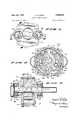
- FIGURE 1 is an end elevational view of one end of the pump, and showing the inlet and outlet thereof;
- FIGURE 2 is a vertical sectional view of the pump shown in FIGURE 1, and taken along the line and in the direction of the arrows 22 of FIGURE 1;
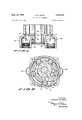
- FIGURE 3 is a vertical sectional view taken along the line and in the direction of the arrows 33 of FIG- URE 2;
- FIGURE 4 is a view of the inside of the end plate shown in FIGURE 1, and illustrating the arrangement of the inlet and outlet parts of the pump assembly, and taken along the line and in the direction of the arrows 44 of FIGURE 1; and
- FIGURE 5 is a view similar to FIGURE 3, and showing a rotor of a somewhat modified design.
- the pump generally designated includes a housing portion 11 together with a rotor assemblage 12 journaled therein.
- the elements are so arranged that the pump is driven from the right as shown in FIGURE 2, and all of the fluid flow is substantially axial of the rotor and occurs through the porting disclosed to the left as shown in the same view, this flow including both the inlet and outlet.
- the porting may be arranged on opposite end faces of the pump assembly, if desired.
- the housing 11 may be conveniently formed from an assembly including a pair of end plates 14 and 15 together with a cylindrical sleeve portion 16 disposed there between.
- Each of the end plates 14 and 15 is provided with a circumferential groove as indicated at 18, in order to provide for a reception area for the O-rings designated 19-19.
- a cylindrical pumping chamber 20 is defined by the inner circumferential walls of the end plates 14 and 15, along with the inner surface of the cylindrical sleeve 16.
- through bolts 2222 are provided for reception in thru-bores formed in the end plate 14, and for further reception in the tapped bores in the end plate 15.
- the end plates 14 and 15 are further provided with substantially identical boss areas 24 and 25, each of these bosses having openings there through for receiving the driveshaft and the appropriate bearing members therein.
- a shaft opening 27 is formed in the end plate 14, and a complementary shaft receiving area 28 is formed in the end plate 15, with appropriate bearing assemblies 29 and 30 being disposed in each of these boss areas, respectively.
- These bearings 29 and 30 are preferably roller-bearing assemblies and lie against an appropriate shouldered area 32 and 33 in each of the boss areas.
- Shaft seals 35 and 36 are diposed between the pumping chamber 20 and the individual bearings 29 and 30.
- a weep hole may be provided in the area of the bearings to permit any fluid which may have passed the seals 35 or 36 to drip outwardly from between the bearing assemblies and the shaft seals.
- the shaft is arranged for free rotation within the confines of the pump asembly 10.
- the end wall 15 is provided with a shallow cavity as at 38, and this cavity communicates with a small passageway, not shown, which leads to the space existing between the shaft seals 35 and 36 and the bearing assemblies 29 and 30.
- any fluid which may escape beyond the seals and into the space occupied by the bearings will be subjected to a reduced pressure resulting from this communication with the suction or inlet side of the pump which has been designated 40, the outlet side being designated 41.
- the outer edge of the individual end plates 14 and 15 have a plurality of openings formed therein, as previously indicated, these openings being adapted to accommodate the cap screws or other devices for arranging the assembly together.
- one or more of the individual cap screws 2222 may be used as a locating screw or the like to assist in orienting the individual end-plates relative to the central sleeve 16.
- the individual screws may be utilized to retain a suitable external mounting structure (not shown).
- marginal relief areas may be provided along the outer portion of the end plate 15 such as is shown at 44 in order to permit complete operability of the individual rollers out to the circumference of the sleeve 16, and thereby .guard against entrapment of any portion of the fluid being pumped.
- the inlet port 40 and the outlet port 41 are formed in the end plate 15.
- the inlet port cavity 45 is formed arcuately about the axis of the shaft opening 46, this shaft opening being adapted to receive the shaft 47 there through.
- This shaft opening 46 is in alignment with the corresponding shaft opening 48 formed in the end plate 14, as illustrated in FIGURE 2.
- These shaft openings 46 and 48 are in axial alignment, each line vertically above the true axial center of the pumping chamber when the end plates are in place.
- Inlet port 45 communicates with the inlet 40, which, as previously indicated, is formed as an integral fixture of the pump.
- An elongated rib 50 runs arcuately for the length of the inlet port 45 and lies in the same plane as the remainder of the inner surface of the plate 15.
- an outlet port 52 which in turn COmmunicates with the outlet 41 formed in the end plate 15.
- This outlet port is, as is the case with the inlet port 45, integrally formed with the end plate 15.
- An elongated rib 53 extends arcuately for the length of the outlet port 52, substantially similar to its counterpart rib 50. As was the case with the rib 50, rib 53 lies in the same plane with the remainder of the end wall formed at the inner surface of the end plate 15.
- the rotor assembly 12 has a rotor body 60 of substantially circular shape which in turn is mounted upon the shaft 47 and secured thereto by means of a set-screw, keyway or the like.
- the shaft 47 is, as indicated, journaled through the bearings 29 and for free rotation therein, and is further journaled through the seals and 36.
- the shaft 47 extends outwardly of the pump housing to the right as shown in FIGURE 2, in order to permit coupling to a suitable power source.
- the outer peripheral surface 61 of the rotor 60 is substantially concentric with the axis of the shaft 47, however is eccentric with respect to the inner surface of the sleeve 16 and consequently with respect to the pumping chamber 20.
- the upper portion of the peripheral surface 61 is substantially in contact with the inner surface of the sleeve 16 as shown in FIGURE 3, while the lower portion is substantially spaced therefrom and defines positive pumping spaces, the volume of which changes as the rotor body '60 rotates within the pumping chamber.
- a plurality of roller receiving slots 62 Formed across the rotor body 60 and extending radially inwardly are a plurality of roller receiving slots 62. Each of these slots has a leading face 63, a trailing face 64, which confront one another in spaced, substantially parallel relationship.
- a cylindrical roller 65 is disposed within each of the slots 62 and is radially movable inwardly and outwardly Within each slot.
- An important feature of the invention resides in the arrangement of the cavity area shown at 66, which is generally inwardly of the slot area 62.
- the depth of the slot area 62 is substantially equal to the diameter of the roller elements 62, however the arcuate extension zones 67 and 68 of the slot 62 provide a reservoir chamber for retaining a quantity of the fluid beind pumped.
- roller elements 65 may be depressed substantially the entire depth of the slots 62, without having to force the fluid outwardly of the slot area. It is important that the arcuate extension zones '67 and 68 do not come in close contact, one to another, in order to provide a substantial web 69 of material between adjacent slots.
- the rotor 12 is disposed in sliding contact with the inner surfaces of the end plates 14 and 15, as best shown in FIGURE 2, and the shaft 47 together with the rotor body 60 rotates in a counter-clockwise direction as viewed in FIGURE 3.
- the individual rollers 65 are thrown outwardly by centrifugal force so as to substantially ride against the inner circumferenital surface of the sleeve 16, and also to slide against the trailing surface 64 of each of the slots '62.
- the clearance between each roller 65 and the leading surface 63 is generally small in order to preventundesired passage of fluid from the area generally beneath the roller 65.
- each roller moves with the rotor 60, it maintains contact with the inner circumferential surface of the sleeve 16 at the inside of the sleeve 16, and begins to move outwardly in its slot 62 as the outer circumference of the rotor leaves the inner housing surface.
- the rollers 65 also, generally, lightly contact the end wall surfaces of the end plates 14 and 15, and as the rollers continue over the inlet port 40, the expanding space 66 beneath the roller causes fluid to be pulled in from the inlet 40 to occupy the space beneath each roller 65.
- the space outwardly of the rotor body 60 and between consecutive rotors begins to increase and likewise exerts a pulling force on the fluid in the inlet port 45. Since the rib is arcuate and continuous for the length of the inlet port 45, each roller 65 is maintained in proper lateral position as it passes thereover.
- the small passageway 38 which connects the inlet port to the space between the bearing 30 and the seal 36 permits a suction force upon this space. Therefore, any liquid which may be trapped in the space is pulled back into the rotor and is inter-mixed with the fluid being pumped.
- the inlet port 45 terminates short of the area of maximum outer travel of each of the rollers '65 and hence there is no further intake of fluid from the inlet 45 through inlet port 40.
- the space between the rotor body 60 and the inner circumference of the sleeve 16 begins to diminish.
- the roller 65 arrives at the upper-most portion of travel along the inner circumference of the sleeve 16, and there is depressed substantially the entire radial length inwardly into the slot 62. At this point, a seal is effected between the inlet side and outlet side of the pump, and as the rotor 60 continues to rotate, it again brings the individual roller designated 65 into proximity with the extreme end of the inlet port 45.
- Each of the arcuate extensions 67 and 68 of the slots 62 create a reservoir area which is constantly maintained within the apparatus. This reservoir diminishes the radial velocity of fluid moving outwardly of the slot area, and further provides a cushioning affect for the rollers 65 within the individual slot areas 62. In this manner, cavitation may be reduced due to the velocity of fluid moving between the rollers and the trailing and leading surfaces 64 and 63 of the slots respectively.
- FIGURE 5 of the drawings which a modified form of rotor assembly is shown.
- the rotor 70 employs a slot area 71 which has a trailing surface 72 and a leading surface 73, the roller 65 being arranged therebetween.
- Arcuate extensions 75 and 76 are shown on opposite sides of the inward extremity of the slot 71, and they are for the same purpose of providing an inwardly disposed reservoir chamber as previously described in the apparatus shown in FIGURES 1-4.
- the trailing surface 72 and the leading surface 73 it will :be observed that these surfaces are in generally mutually parallel relationship, one with another.
- the trailing surface 72 is disposed along the radius lure of the rotor body 70.
- This arrangement enables the roller 65 to be moved generally outwardly a distance greater than would otherwise be possible if the center line of the slot 71 were generally along a radius line of the rotor 70.
- the remaining operating features of this assembly are essentially the same as those shown in the modification of FIGURES 1-4, the only distinction being in the arrangement of the trailing and leading surfaces 72 and 73 of the slot areas 71.
- a fluid pump comprising:
- said pumping chamber being defined by an inner circumferential wall and a pair of spaced circular end walls,
- outlet port means formed through one of said walls and arcuately spaced from said inlet port
- said roller receiving slots having leading and trailing surfaces adjacent the outer opening extending across the axial length of said rotor, and defining an access opening to said slot and having a radial depth, the breadth of said access opening being substantially equal to the diameter of said roller, and arcuate extension cavities disposed radially inwardly of said access openings and in communication therewith and being formed within the body of said rotor, each of said extension cavities extending across the width of said rotor and defining a fluid reservoir chamber within said slot, and having an arcuate length which substantially exceeds the arcuate width of said roller receiving slots.
- the fluid pump as defined in claim 1 being par ticularly characterized in that the outer circumferential surface of said rotor is in close running clearance with the inner circumferential surface of said chamber along one radial portion thereof.
- a fluid pump comprising:
- said pumping chamber being defined by an inner circumferential wall and a pair of spaced circular end walls,
- outlet port means formed through one of said walls and arcuately spaced from said inlet port
- roller receiving slots having leading and trailing surfaces adjacent the outer opening and extending across the axial length of said rotor, and defining an access opening to said slot and having a radial depth, the radial depth of said roller receiving slots being substantially equal to the diameter of said rollers, and arcuate extension cavities disposed radially inwardly of said access openings and in communication therewith, and being formed within the body of said rotor, each of said extension cavities extending across the width of said rotor and defining a fluid reservoir chamber within said slot, and having an arcuate length which substantially exceeds the arcuate width of said roller receiving slots.
- the fluid pump as defined in claim 5 being particularly characterized in that the arcuate width of said access opening is substantially equal to the diameter of said roller.
- the fluid pump as defined in claim 5 being particularly characterized in that the outer circumferential surface of said rotor is disposed in close running clearance with the inner circumferential surface of said chamber along one radial portion thereof.
Landscapes
- Engineering & Computer Science (AREA)
- Mechanical Engineering (AREA)
- General Engineering & Computer Science (AREA)
- Rotary Pumps (AREA)
Description
Sept. 24, 1968 E. E. COOK 3,
ROLLER PUMP ASSEMBLY Filed April 21, 1966 2 Sheets-Sheet l INVENTOR.
, BY d Sept. 24, 1968 E. E. COOK 3,402,672
11ed April 21, 1966 2 Sheets-Sheet 2 ,IIIII 6 k a/a ulllh 1 5,
INVENTOR. ERA/:57 Came United States Patent ABSTRACT OF THE DISCLOSURE A roller pump comprising a cylindrical pumping chamber having a rotor rotatably mounted therewithin, and being provided with a plurality of roller receiving slots, each slot being generally radially disposed within said rotor and having leading and trailing surfaces for controlling the disposition of the roller, each of said slots having an arcuate extension cavity extending across the width of the rotor and defining a fluid reservoir chamber within the slot, the arcuate extension cavity having an arcuate length which substantially exceeds the arcuate width of the individual roller receiving slot.
This invention relates to rotary pumps and more particularly to rotary pumps of the type which employ freefloating roller elements held captive within slots formed in a rotor assembly.
It is an important object of the invention to provide a pump of the class described which has an extremely high capacity for its size, and which is eflicient and economical, both in manufacture and in its operation.
It is a further object of this present invention to provide a rotor and roller assemblage which maintains a fluid piston in connection with each of the rollers so as to increase the efficiency of the fluid flow under high speed operating conditions, and which also reduces the noise and wear within the various elements or components of the pump.
Yet a further object of the present invention is to provide a pump assembly which has an enhanced sealing arrangement between the suction side and the pressure side of the pump, so as to increase the efficiency of its operation.
Yet a further object of the present invention is to provide a pump having an operating characteristic such that the individual rollers are maintained in reasonably parallel relationship with the axis of the rotor.
These and other objects and advantages of this invention will more fully appear from the following description, made in accordance with the accompanying drawings, wherein like reference characters refer to the same or similar parts throughout the several views and in which:
FIGURE 1 is an end elevational view of one end of the pump, and showing the inlet and outlet thereof;
FIGURE 2 is a vertical sectional view of the pump shown in FIGURE 1, and taken along the line and in the direction of the arrows 22 of FIGURE 1;
FIGURE 3 is a vertical sectional view taken along the line and in the direction of the arrows 33 of FIG- URE 2;
FIGURE 4 is a view of the inside of the end plate shown in FIGURE 1, and illustrating the arrangement of the inlet and outlet parts of the pump assembly, and taken along the line and in the direction of the arrows 44 of FIGURE 1; and
FIGURE 5 is a view similar to FIGURE 3, and showing a rotor of a somewhat modified design.
In accordance with the preferred modification of the present invention, and with particular reference to FIG- URES 1-4 of the drawings, it will be seen that the pump generally designated includes a housing portion 11 together with a rotor assemblage 12 journaled therein. The elements are so arranged that the pump is driven from the right as shown in FIGURE 2, and all of the fluid flow is substantially axial of the rotor and occurs through the porting disclosed to the left as shown in the same view, this flow including both the inlet and outlet. It will be recognized, of course, that the porting may be arranged on opposite end faces of the pump assembly, if desired.
The housing 11 may be conveniently formed from an assembly including a pair of end plates 14 and 15 together with a cylindrical sleeve portion 16 disposed there between. Each of the end plates 14 and 15 is provided with a circumferential groove as indicated at 18, in order to provide for a reception area for the O-rings designated 19-19. A cylindrical pumping chamber 20 is defined by the inner circumferential walls of the end plates 14 and 15, along with the inner surface of the cylindrical sleeve 16. In order to retain the assembly in proper pre-assembled form, through bolts 2222 are provided for reception in thru-bores formed in the end plate 14, and for further reception in the tapped bores in the end plate 15. The end plates 14 and 15 are further provided with substantially identical boss areas 24 and 25, each of these bosses having openings there through for receiving the driveshaft and the appropriate bearing members therein. A shaft opening 27 is formed in the end plate 14, and a complementary shaft receiving area 28 is formed in the end plate 15, with appropriate bearing assemblies 29 and 30 being disposed in each of these boss areas, respectively. These bearings 29 and 30 are preferably roller-bearing assemblies and lie against an appropriate shouldered area 32 and 33 in each of the boss areas. Shaft seals 35 and 36 are diposed between the pumping chamber 20 and the individual bearings 29 and 30. If desired, a weep hole may be provided in the area of the bearings to permit any fluid which may have passed the seals 35 or 36 to drip outwardly from between the bearing assemblies and the shaft seals. Thus, the shaft is arranged for free rotation within the confines of the pump asembly 10. As shown in phantom in FIGURE 3, the end wall 15 is provided with a shallow cavity as at 38, and this cavity communicates with a small passageway, not shown, which leads to the space existing between the shaft seals 35 and 36 and the bearing assemblies 29 and 30. Thus, any fluid which may escape beyond the seals and into the space occupied by the bearings will be subjected to a reduced pressure resulting from this communication with the suction or inlet side of the pump which has been designated 40, the outlet side being designated 41.
It will be observed from FIGURES 2 and 3 that, while the cylindrical pumping chamber is generally circular in configuration, the shaft opening formed in the, end plates 14 and 15 is somewhat above the true center axis of the pumping chamber 20.
The outer edge of the individual end plates 14 and 15 have a plurality of openings formed therein, as previously indicated, these openings being adapted to accommodate the cap screws or other devices for arranging the assembly together. If desired, one or more of the individual cap screws 2222 may be used as a locating screw or the like to assist in orienting the individual end-plates relative to the central sleeve 16. Also, of desired, the individual screws may be utilized to retain a suitable external mounting structure (not shown). If desired, marginal relief areas may be provided along the outer portion of the end plate 15 such as is shown at 44 in order to permit complete operability of the individual rollers out to the circumference of the sleeve 16, and thereby .guard against entrapment of any portion of the fluid being pumped.
As previously indicated, the inlet port 40 and the outlet port 41 are formed in the end plate 15. The inlet port cavity 45 is formed arcuately about the axis of the shaft opening 46, this shaft opening being adapted to receive the shaft 47 there through. This shaft opening 46 is in alignment with the corresponding shaft opening 48 formed in the end plate 14, as illustrated in FIGURE 2. These shaft openings 46 and 48 are in axial alignment, each line vertically above the true axial center of the pumping chamber when the end plates are in place. Inlet port 45 communicates with the inlet 40, which, as previously indicated, is formed as an integral fixture of the pump. An elongated rib 50 runs arcuately for the length of the inlet port 45 and lies in the same plane as the remainder of the inner surface of the plate 15.
Substantially diametrically opposite from the inlet port 45 is an outlet port 52 which in turn COmmunicates with the outlet 41 formed in the end plate 15. This outlet port is, as is the case with the inlet port 45, integrally formed with the end plate 15. An elongated rib 53 extends arcuately for the length of the outlet port 52, substantially similar to its counterpart rib 50. As was the case with the rib 50, rib 53 lies in the same plane with the remainder of the end wall formed at the inner surface of the end plate 15.
The rotor assembly 12 has a rotor body 60 of substantially circular shape which in turn is mounted upon the shaft 47 and secured thereto by means of a set-screw, keyway or the like. The shaft 47 is, as indicated, journaled through the bearings 29 and for free rotation therein, and is further journaled through the seals and 36. The shaft 47 extends outwardly of the pump housing to the right as shown in FIGURE 2, in order to permit coupling to a suitable power source. The outer peripheral surface 61 of the rotor 60 is substantially concentric with the axis of the shaft 47, however is eccentric with respect to the inner surface of the sleeve 16 and consequently with respect to the pumping chamber 20. The upper portion of the peripheral surface 61 is substantially in contact with the inner surface of the sleeve 16 as shown in FIGURE 3, while the lower portion is substantially spaced therefrom and defines positive pumping spaces, the volume of which changes as the rotor body '60 rotates within the pumping chamber.
Formed across the rotor body 60 and extending radially inwardly are a plurality of roller receiving slots 62. Each of these slots has a leading face 63, a trailing face 64, which confront one another in spaced, substantially parallel relationship. A cylindrical roller 65 is disposed within each of the slots 62 and is radially movable inwardly and outwardly Within each slot. An important feature of the invention resides in the arrangement of the cavity area shown at 66, which is generally inwardly of the slot area 62. The depth of the slot area 62 is substantially equal to the diameter of the roller elements 62, however the arcuate extension zones 67 and 68 of the slot 62 provide a reservoir chamber for retaining a quantity of the fluid beind pumped. Thus, the roller elements 65 may be depressed substantially the entire depth of the slots 62, without having to force the fluid outwardly of the slot area. It is important that the arcuate extension zones '67 and 68 do not come in close contact, one to another, in order to provide a substantial web 69 of material between adjacent slots.
In the use and operation of the pump of the present invention, the rotor 12 is disposed in sliding contact with the inner surfaces of the end plates 14 and 15, as best shown in FIGURE 2, and the shaft 47 together with the rotor body 60 rotates in a counter-clockwise direction as viewed in FIGURE 3. The individual rollers 65 are thrown outwardly by centrifugal force so as to substantially ride against the inner circumferenital surface of the sleeve 16, and also to slide against the trailing surface 64 of each of the slots '62. The clearance between each roller 65 and the leading surface 63 is generally small in order to preventundesired passage of fluid from the area generally beneath the roller 65. As each roller moves with the rotor 60, it maintains contact with the inner circumferential surface of the sleeve 16 at the inside of the sleeve 16, and begins to move outwardly in its slot 62 as the outer circumference of the rotor leaves the inner housing surface. The rollers 65 also, generally, lightly contact the end wall surfaces of the end plates 14 and 15, and as the rollers continue over the inlet port 40, the expanding space 66 beneath the roller causes fluid to be pulled in from the inlet 40 to occupy the space beneath each roller 65. Also, it will be noted that the space outwardly of the rotor body 60 and between consecutive rotors begins to increase and likewise exerts a pulling force on the fluid in the inlet port 45. Since the rib is arcuate and continuous for the length of the inlet port 45, each roller 65 is maintained in proper lateral position as it passes thereover.
As previously noted, the small passageway 38 which connects the inlet port to the space between the bearing 30 and the seal 36 permits a suction force upon this space. Therefore, any liquid which may be trapped in the space is pulled back into the rotor and is inter-mixed with the fluid being pumped. The inlet port 45 terminates short of the area of maximum outer travel of each of the rollers '65 and hence there is no further intake of fluid from the inlet 45 through inlet port 40. However, as the rotor continues its travel in a counter-clockwise direction as shown in FIGURE 3, the space between the rotor body 60 and the inner circumference of the sleeve 16 begins to diminish. Shortly thereafter, it reaches the lower end of the outlet port 52 and again the roller members ride upon the rib area 53 in order to eliminate axial displacement of the rollers 65. The liquid which has previously been pulled into the slot 62 in the space beneath the roller 65 is now caused to move laterally outwardly of the rotor 60 and accordingly be discharged through the outlet port 41. In a similar manner, the liquid forwardly of the roller 65 is caused to be squeezed into the outlet port area 52. The ports are thus self-valving in character and the consecutive increasing and diminishing volumes associated with each roller causes a continuous flow of liquid into the inlet 45 and out of the outlet 52. Continuing on in its counter-clockwise movement, the roller 65 arrives at the upper-most portion of travel along the inner circumference of the sleeve 16, and there is depressed substantially the entire radial length inwardly into the slot 62. At this point, a seal is effected between the inlet side and outlet side of the pump, and as the rotor 60 continues to rotate, it again brings the individual roller designated 65 into proximity with the extreme end of the inlet port 45.
Each of the arcuate extensions 67 and 68 of the slots 62 create a reservoir area which is constantly maintained within the apparatus. This reservoir diminishes the radial velocity of fluid moving outwardly of the slot area, and further provides a cushioning affect for the rollers 65 within the individual slot areas 62. In this manner, cavitation may be reduced due to the velocity of fluid moving between the rollers and the trailing and leading surfaces 64 and 63 of the slots respectively.
The arrangement as described makes it possible for the inlet and outlet to be located on either the same or opposite end plates of the pump assembly. While the arrangement disclosed herein shows the inlet and outlet to be disposed on the same end plate, it will be appreciated that the assembly will work equally well with the inlet and outlet arranged on oppositely disposed end plates. The radial disposition of these ports will, of course, necessarily be as shown in FIGURE 1.
Special attention is now directed to FIGURE 5 of the drawings which a modified form of rotor assembly is shown. In this arrangement, the rotor 70 employs a slot area 71 which has a trailing surface 72 and a leading surface 73, the roller 65 being arranged therebetween. Arcuate extensions 75 and 76 are shown on opposite sides of the inward extremity of the slot 71, and they are for the same purpose of providing an inwardly disposed reservoir chamber as previously described in the apparatus shown in FIGURES 1-4. With particular attention being directed to the trailing surface 72 and the leading surface 73, it will :be observed that these surfaces are in generally mutually parallel relationship, one with another. In addition, it will be observed that the trailing surface 72 is disposed along the radius lure of the rotor body 70. This arrangement enables the roller 65 to be moved generally outwardly a distance greater than would otherwise be possible if the center line of the slot 71 were generally along a radius line of the rotor 70. The remaining operating features of this assembly are essentially the same as those shown in the modification of FIGURES 1-4, the only distinction being in the arrangement of the trailing and leading surfaces 72 and 73 of the slot areas 71.
It will be appreciated that those specific modifications given herein are for purposes of illustration only, and that those skilled in the art may depart from these specific embodiments or illustrations without necessarily departing from the spirit and scope of the present invention.
What is claimed is:
1. A fluid pump comprising:
(a) a housing having a cylindrical pumping chamber therein,
(b) said pumping chamber being defined by an inner circumferential wall and a pair of spaced circular end walls,
(0) a rotor rotatably mounted within said pumping chamber and having its axis in offset parallel relation to that of said pumping chamber and having a width such as to extend from one of said circular end walls to the other,
(d) said rotor having a plurality of roller receiving slots formed into and across the circumferential surface thereof,
(e) a roller disposed for free rotation in each of said slots in close clearance with the sides thereof adjacent to the radially outwardly disposed portions of the sides thereof and extending from one of said circular end walls to the other,
(f) inlet port means formed through one of said walls,
(g) outlet port means formed through one of said walls and arcuately spaced from said inlet port, and
(h) said roller receiving slots having leading and trailing surfaces adjacent the outer opening extending across the axial length of said rotor, and defining an access opening to said slot and having a radial depth, the breadth of said access opening being substantially equal to the diameter of said roller, and arcuate extension cavities disposed radially inwardly of said access openings and in communication therewith and being formed within the body of said rotor, each of said extension cavities extending across the width of said rotor and defining a fluid reservoir chamber within said slot, and having an arcuate length which substantially exceeds the arcuate width of said roller receiving slots.
2. The fluid pump as defined in claim 1 being particularly characterized in that said arcuate extension cavities extend arcuately a substantially equal distance from each of said leading and trailing surfaces.
3. The fluid pump as defined in claim 1 being par ticularly characterized in that the outer circumferential surface of said rotor is in close running clearance with the inner circumferential surface of said chamber along one radial portion thereof.
4. The fluid pump as defined in claim 1 being particularly characterized in that said trailing surface is disposed generally along a radius line of said rotor.
5. A fluid pump comprising:
(a) a housing having a cylindrical pumping chamber therein,
(b) said pumping chamber being defined by an inner circumferential wall and a pair of spaced circular end walls,
(c) a rotor rotatably mounted within said pumping chamber and having its axis in offset parallel relation to that of said pumping chamber and having a width such as to extend from one of said circular end walls to the other,
(d) said rotor having a plurality of roller receiving slots formed into and across the circumferential surface thereof,
(e) a roller disposed for free rotation in each of said slots in close clearance with the sides thereof adjacent to the radially outwardly disposed portions of the sides thereof and extending from one of said circular end walls to the other,
(f) inlet port means formed through one of said walls,
(g) outlet port means formed through one of said walls and arcuately spaced from said inlet port, and
(h) said roller receiving slots having leading and trailing surfaces adjacent the outer opening and extending across the axial length of said rotor, and defining an access opening to said slot and having a radial depth, the radial depth of said roller receiving slots being substantially equal to the diameter of said rollers, and arcuate extension cavities disposed radially inwardly of said access openings and in communication therewith, and being formed within the body of said rotor, each of said extension cavities extending across the width of said rotor and defining a fluid reservoir chamber within said slot, and having an arcuate length which substantially exceeds the arcuate width of said roller receiving slots.
6. The fluid pump as defined in claim 5 being particularly characterized in that the arcuate width of said access opening is substantially equal to the diameter of said roller.
7. The fluid pump as defined in claim 5 being particularly characterized in that the outer circumferential surface of said rotor is disposed in close running clearance with the inner circumferential surface of said chamber along one radial portion thereof.
8. The fluid pump as defined in claim 5 being particularly characterized in that the trailing surface of said slots is disposed generally along a radius line of said rotor.
References Cited UNITED STATES PATENTS 2,460,018 1/1949 Looke l03136 2,589,449 3/1952 Stageberg 103-136 3,072,067 1/1963 Beller l03l36 3,253,546 5/1966 Cook l03-l36 3,266,431 8/1966 Cook 103-136 FRED C. MATTERN, JR., Primary Examiner.
WILBUR J. GOODLIN, Assistant Examiner.
Priority Applications (1)
| Application Number | Priority Date | Filing Date | Title |
|---|---|---|---|
| US544135A US3402672A (en) | 1966-04-21 | 1966-04-21 | Roller pump assembly |
Applications Claiming Priority (1)
| Application Number | Priority Date | Filing Date | Title |
|---|---|---|---|
| US544135A US3402672A (en) | 1966-04-21 | 1966-04-21 | Roller pump assembly |
Publications (1)
| Publication Number | Publication Date |
|---|---|
| US3402672A true US3402672A (en) | 1968-09-24 |
Family
ID=24170899
Family Applications (1)
| Application Number | Title | Priority Date | Filing Date |
|---|---|---|---|
| US544135A Expired - Lifetime US3402672A (en) | 1966-04-21 | 1966-04-21 | Roller pump assembly |
Country Status (1)
| Country | Link |
|---|---|
| US (1) | US3402672A (en) |
Cited By (2)
| Publication number | Priority date | Publication date | Assignee | Title |
|---|---|---|---|---|
| US4692105A (en) * | 1984-05-21 | 1987-09-08 | Andre Leroy | Roller displacement motor |
| US20040219046A1 (en) * | 2003-05-01 | 2004-11-04 | Sauer-Danfoss Inc. | Roller vane pump |
Citations (5)
| Publication number | Priority date | Publication date | Assignee | Title |
|---|---|---|---|---|
| US2460018A (en) * | 1945-05-03 | 1949-01-25 | Looke Harry Hansen | Roller vane rotary pump |
| US2589449A (en) * | 1943-10-15 | 1952-03-18 | Sterling O Stageberg | Movable vane pump |
| US3072067A (en) * | 1959-12-22 | 1963-01-08 | Eaton Mfg Co | Rotary pump |
| US3253546A (en) * | 1963-10-30 | 1966-05-31 | Hypro Inc | Combination side and end port pump |
| US3266431A (en) * | 1963-12-09 | 1966-08-16 | Hypro Inc | End ported pump having an improved porting arrangement |
-
1966
- 1966-04-21 US US544135A patent/US3402672A/en not_active Expired - Lifetime
Patent Citations (5)
| Publication number | Priority date | Publication date | Assignee | Title |
|---|---|---|---|---|
| US2589449A (en) * | 1943-10-15 | 1952-03-18 | Sterling O Stageberg | Movable vane pump |
| US2460018A (en) * | 1945-05-03 | 1949-01-25 | Looke Harry Hansen | Roller vane rotary pump |
| US3072067A (en) * | 1959-12-22 | 1963-01-08 | Eaton Mfg Co | Rotary pump |
| US3253546A (en) * | 1963-10-30 | 1966-05-31 | Hypro Inc | Combination side and end port pump |
| US3266431A (en) * | 1963-12-09 | 1966-08-16 | Hypro Inc | End ported pump having an improved porting arrangement |
Cited By (3)
| Publication number | Priority date | Publication date | Assignee | Title |
|---|---|---|---|---|
| US4692105A (en) * | 1984-05-21 | 1987-09-08 | Andre Leroy | Roller displacement motor |
| US20040219046A1 (en) * | 2003-05-01 | 2004-11-04 | Sauer-Danfoss Inc. | Roller vane pump |
| US6857862B2 (en) * | 2003-05-01 | 2005-02-22 | Sauer-Danfoss Inc. | Roller vane pump |
Similar Documents
| Publication | Publication Date | Title |
|---|---|---|
| US2832293A (en) | Vane pump | |
| US2278131A (en) | Pump | |
| KR890004076A (en) | Fluid pump device | |
| US2891482A (en) | Rotary machine adapted to operate as a pump or as a fluid motor | |
| US3213803A (en) | Rotary pump | |
| US3711227A (en) | Vane-type fluid pump | |
| US2969743A (en) | Rotary slidable-vane machines | |
| US2132812A (en) | Rotary engine | |
| US3451346A (en) | Power transmission | |
| US2880677A (en) | Variable volume vane pump | |
| US1350159A (en) | Air-compressor | |
| US3194168A (en) | Fluid pumps | |
| US3402672A (en) | Roller pump assembly | |
| US3119345A (en) | End ported roller pump | |
| US2677330A (en) | Vane pump | |
| US1749058A (en) | Rotary pump | |
| US2487685A (en) | Rotary oscillating vane pump | |
| US4331420A (en) | Reversible unidirectional flow pump with frictionally engaged axial valve plate | |
| US2068570A (en) | Rotary pump | |
| US2453266A (en) | Piston pump | |
| USRE25973E (en) | End ported roller pump | |
| US1945220A (en) | Rotary pump machine | |
| US3331326A (en) | Rotary pump | |
| US2703675A (en) | Rotary pump | |
| ES342442A1 (en) | Rotary pumps |