US3402659A - Electrical printing processes employing two fields of different strengths - Google Patents
Electrical printing processes employing two fields of different strengths Download PDFInfo
- Publication number
- US3402659A US3402659A US575868A US57586866A US3402659A US 3402659 A US3402659 A US 3402659A US 575868 A US575868 A US 575868A US 57586866 A US57586866 A US 57586866A US 3402659 A US3402659 A US 3402659A
- Authority
- US
- United States
- Prior art keywords
- screen
- particles
- powder
- article
- article surface
- Prior art date
- Legal status (The legal status is an assumption and is not a legal conclusion. Google has not performed a legal analysis and makes no representation as to the accuracy of the status listed.)
- Expired - Lifetime
Links
- 238000000034 method Methods 0.000 title description 28
- 239000002245 particle Substances 0.000 description 75
- 239000000843 powder Substances 0.000 description 60
- 230000005684 electric field Effects 0.000 description 40
- 230000000694 effects Effects 0.000 description 11
- 239000011248 coating agent Substances 0.000 description 7
- 238000000576 coating method Methods 0.000 description 7
- 238000010586 diagram Methods 0.000 description 5
- 229910000831 Steel Inorganic materials 0.000 description 3
- 230000004323 axial length Effects 0.000 description 3
- 239000003086 colorant Substances 0.000 description 3
- 239000010959 steel Substances 0.000 description 3
- 230000015556 catabolic process Effects 0.000 description 2
- 239000011521 glass Substances 0.000 description 2
- 239000000203 mixture Substances 0.000 description 2
- 241001255741 Vanna Species 0.000 description 1
- 238000000418 atomic force spectrum Methods 0.000 description 1
- 230000003190 augmentative effect Effects 0.000 description 1
- 238000011109 contamination Methods 0.000 description 1
- 238000005034 decoration Methods 0.000 description 1
- 230000001419 dependent effect Effects 0.000 description 1
- 230000001627 detrimental effect Effects 0.000 description 1
- 239000011810 insulating material Substances 0.000 description 1
- 239000000463 material Substances 0.000 description 1
- 239000012811 non-conductive material Substances 0.000 description 1
- 238000002360 preparation method Methods 0.000 description 1
- 230000001105 regulatory effect Effects 0.000 description 1
- 230000000284 resting effect Effects 0.000 description 1
- 230000001360 synchronised effect Effects 0.000 description 1
Images
Classifications
-
- B—PERFORMING OPERATIONS; TRANSPORTING
- B41—PRINTING; LINING MACHINES; TYPEWRITERS; STAMPS
- B41M—PRINTING, DUPLICATING, MARKING, OR COPYING PROCESSES; COLOUR PRINTING
- B41M1/00—Inking and printing with a printer's forme
- B41M1/12—Stencil printing; Silk-screen printing
- B41M1/125—Stencil printing; Silk-screen printing using a field of force, e.g. an electrostatic field, or an electric current
-
- Y—GENERAL TAGGING OF NEW TECHNOLOGICAL DEVELOPMENTS; GENERAL TAGGING OF CROSS-SECTIONAL TECHNOLOGIES SPANNING OVER SEVERAL SECTIONS OF THE IPC; TECHNICAL SUBJECTS COVERED BY FORMER USPC CROSS-REFERENCE ART COLLECTIONS [XRACs] AND DIGESTS
- Y10—TECHNICAL SUBJECTS COVERED BY FORMER USPC
- Y10S—TECHNICAL SUBJECTS COVERED BY FORMER USPC CROSS-REFERENCE ART COLLECTIONS [XRACs] AND DIGESTS
- Y10S101/00—Printing
- Y10S101/37—Printing employing electrostatic force
Definitions
- a stencil screen having an imagedefining aperture of the desired shape is supported in spaced relationship between a supply of powder and the surface of the article to be printed.
- the supply of powder is supported upon an electrically conductive element, and the screen takes the form of a fine wire mesh with the openings between the mesh blocked by a coating, except in those regions constituting the image-defining apertures.
- an electric voltage source can be connected between the electrically conductive element and screen to establish an electric field which charges the powder particles on the conductive element and electrically attracts the particles toward the screen.
- an electric field of sufficient strength applied many of the powder particles are accelerated to a velocity suflicient to pass through the screen at the image-defining apertures and continue to the surface of the article.
- an electric potential is also established between the screen and article surface.
- Retransfer is encountered when particles striking the article surface become oppositely charged and electrically repelled. Retransfer reduces the density of the image applied to the surface and may be said to reduce the efficiency of transfer. Retransferred particles may make one or more round trips between the supply and article surface or screen and article surface.
- Aerodynamic effects occur because of the fact that an extremely large number of lightweight particles are simultaneously impelled across a relatively small air space, creating turbulent air currents which are primarily effective near the outer edges of the image area. This effect can usually be detected by an image which becomes gradually less dense near the edges, by virtue of the presence of a greater percentage of smaller particles being carried by air currents toward the edge zone.
- the powder layer is firmly packed against the article surface and, in the absence of undue mechanical disturbance, will remain in its originally applied condition. Because there is no mechanical contact between the screen and article surface, a second layer of powder may be applied to the article surface in adjacent or overlapping relationship to the first applied layer without specially treating or fixing the first layer prior to application of the second.
- the problems of retransfer, scattering or lack of resolution discussed are of especial concern in multicolor operations, since retransfer, entirely apart from non-uniform density, can cause contamination of powder supplies by retransfer of one color powder from the article to a powder supply of a different color powder. Scattering or lack of resolution is much more noticeable at the juncture of image layers of contrasting colors.
- FIGURE 1 is a schematic diagram of one form of the invention
- FIGURE 2 is a schematic diagram of another form of the invention.
- FIGURE 3 is a schematic diagram illustrating the effect of an electric field applied Only between the powder supply and stencil screen.
- FIGURE 4 is a schematic diagram illustrating the effect of an electric field applied between supply and screen and a second electric field applied between screen and article surface.
- FIGURE 1 there is disclosed a preferred embodiment of the invention in diagrammatic form.
- a supply of printing powder particles indicated at 10 is loosely piled in a layer of substantially uniform thickness upon the surface of an electrically conductive plate 12.
- a coated wire mesh stencil screen 14 is supported in spaced relationship above the surface of powder supply 10 and in spaced relationship below the surface of an article to be decorated, illustrated schematically at 16.
- Stencil screen 14 takes the form of a relatively fine mesh steel wire which is covered with a coating which completely fills the openings of the screen mesh.
- the coating is removed from the desired imagedefining portions of the steel mesh to form image-defining apertures, as at 18, of the desired shape.
- the procedure and materials needed for preparation of such a stencil are by a well known photographic or photosensitive process, see, for example, United States Patent No. 3,100,150.
- the openings which define the image are crossed by the wire mesh of the screen and, as illustrated by the example given below, particles of printing powder can pass through the openings of the screen from which the coating has been removed, and thus impinge upon the surface of article 16 in areas corresponding in size and shape to the imagedefining apertures, such as 18, in the stencil screen.
- the portions of screen 14 which remain coated block the passage of particles from supply 10 to the article surface 16.
- Transfer of particles from supply 10 to the surface of article 16 is accomplished by applying electric potentials to plate 12, screen 14 and article 16 to establish an electric field which is operable to electrically charge particles in supply 10 by virtue of their association with plate 12, and electrically impel the particles upwardly from supply 10 through openings 18 in screen 14 to the lower surface of article 16.
- compositions of printing powder or powdered ink suitable for use in the arrangement of FIGURE 1 are presently commercially available.
- the exact composition of the powder employed is dependent upon the desired color, characteristics of the surface to be printed, desired image thickness or density, the type of decoration or printing desired, the electrical properties, and other variable factors.
- the powder employed must, of course, be capable of being electrically charged and of a particle size such that it can easily pass through the mesh of the stencil screen.
- a loose layer approximately of an inch thick of a glass frit powder was supported upon plate 12.
- the frit particles were of a particle size range between 2 and 10 microns, as measured by a Coulter counter or other standard particle size measuring technique.
- the size range of 2 to 10 microns was preferable when used with the specific screen size described below, although an acceptable size range could have extended from 1 to 50 microns.
- the electrical properties of the powder are most conveniently referenced in terms of its electrical resistivity.
- the resistivity of the powder was between 10 and ohm centimeters, as measured by a standard cylindrical cell technique.
- the powder to be measured is poured into a cylindrical container of electrical insulating material to form an unpacked cylindrical body of known cross sectional area and axial length.
- the unpacked powder is then compressed by reducing its axial length by a known amount and the electrical resistance of the packed cylindrical powder body is then measured by applying an electrical potential across its axial length.
- a stencil screen 14 of #200 mesh steel wire was employed.
- the openings in a #200 mesh screen are of the order of fifty times or more the size of particles within the size range referred to above. It is desirable that the screen mesh be larger than the maximum particle size by an order of between 10 and 100, so that bridging or clogging of the mesh openings is avoided.
- a relatively fine mesh is desirable, in order to achieve as uniform a field density as possible over the area of the image apertures.
- the spacing between plate 12 and screen 14, and between screen 14 and the article surface 16, will usually be of the order of A to A of an inch and 0.002 to 0.060 of an inch, respectively.
- the precise spacing is critical primarily in its relationship to the electric potential applied across the spacing, in that the electric field strength is of primary concern, and electric field strength is measured in volts per unit distance of spacing. For uniformity of the electric field, it is necessary that the spacing be uniform.
- relatively high voltage is applied across the space between plate 12 and screen 14, while the article surface 16 is held at a relatively low voltage with respect to the screen, the potentials at plate 12 and article 16 being of opposite polarity.
- the output of the respective high voltage and low voltage supplies schematically shown in FIGURE 1 are such that an electric field having a field strength of between 60 and volts per mil exists between plate 12. and screen 14 and an electric field of between 10 and 25 volts per mil exists between screen 14 and article 16.
- FIGURE 1 A convenient arrangement for applying pulses is illustrated in FIGURE 1 in which a controlled gate connects the output of an oscillator to a power amplifier for the desired pulse interval.
- the ouput of the power amplifier is fed into a high voltage transformer and rectifier whose output in turn is connected across plate 12 and screen 14.
- a DC voltage When a DC voltage is applied, it is applied in the form of a pulsating DC, in order to pass through the transformer.
- a good quality transfer may be defined as one in which the powder particles are packed in a thin layer of uniform density on the surface of article 16 with a high degree of r,esolution, or image sharpness. In order to achieve thisresult, retransfer. and scattering of particles during the transfer must be minimized.
- Retransfer is, believed to occur when a powder particle which, for the sake of example, will be said to be positively-charged,- contacts an article surface which is itself charged to a negative potential. Uponcontact with the negatively. charged surface, the particle may loseits positive charge and become. negatively charged and thus electrically'repelledfrom the negatively charged surface.
- multiple transfers can occur within a relatively short time interval in which a particle may travel back and forth between supply and article -16 several times.
- the reversal of charge upon the particle upon contact with a charged surface does not necessarily occur instantaneously and, under some conditions, it has been observed that the image on the article surface is more dense during early stages of the transfer than in the later stages.
- FIGURE 1 In an attempt to minimize the retransfer problem, the arrangement of FIGURE 1 has been tried with the low voltage supply to the article 16 disconnected. Disconnecting article surface 16 from a voltage source results in an electric field configuration of the type schematically illustrated in FIGURE 3, in which the electric lines of force extend from the surface of plate 12 to the individual wires 14a of screen 14 in the manner indicated at B.
- a potential difference between plate 12 and wires 14a of sufficient magnitude powder particles resting upon plate 12 can be accelerated to velocities high enough so that their momentum carries them clear and beyond the screen to the article surface.
- a second effect detrimental to image resolution where only a plate-to-screen field is applied occurs because the lack of positive guidance of particles in transit between the screen and article surface makes the particles susceptible to turbulent air currents generated by the simultaneous transit of a large number of particles through a given air space.
- FIGURE 4 When, in addition to the establishment of an electric field between plate 12 and screen 14, a second field is established between screen 14 and the article surface, an electric field configuration somewhat similar to that schematically illustrated in FIGURE 4 exists.
- the first electric field extends between plate 12 and the individual wires 14a of the screen, as in the FIGURE 3 arrangement, the electric lines of force of the first field being indicated at E1 in FIGURE 4, while a second series of lines of force E2 extend from the individual Wires 14a to the article surface.
- a typical particle path is illustrated in dotted lines at P1 in FIGURE 4, and it will be observed that, although the particle is deflected somewhat toward the nearest screen wire 14a as it leaves the lower field, the orientation of the lines of force E2 of the upper field tend to deflect the particle back toward vertical alignment with the point from which it left plate 12.
- the lower or particle accelerating field is preferably made of as high a field strength as possible without reaching the breakdown point of the dielectric medium-air in the usual case. It has been found that breakdown, or sparking, in an air environment begins to occur at field strengths over volts per mil. For transfer of a glass frit, such as in the specific example described above, a minimum or threshold field strength of the field between plate 12 and screen 14 of 30 to 35 volts per mil has been found to be the minimum strength necessary for satisfactory operation.
- the lower or accelerating field strength should be sufficient to electrically charge particles in the supply and impel the particles through the screen with sufficient velocity to impinge on the article surface, even in the absence of an upper field.
- the upper field strength should be as high as possible to enable this field to perform its particle guiding or focusing function without being so high as to cause retransfer problems.
- FIGURE 2 an alternative form of the invention is disclosed which, in essence, differs from the FIGURE 1 embodiment in that the electrical focusing action referred to above is further augmented by the employment of a second mechanical focusing or collimating screen 20 which is located between an electrically conductive screen 22 and the article 24 being decorated.
- an electrically conductive plate 26 is employed to support a supply of printing powder particles indicated at 28, the supply, screens and articles all being maintained in a spaced relationship to each other.
- a common, high voltage source is connected across article 24, screen 22 and plate 26 by variable voltage dividing resistances R1 and R2 which may be adjusted as desired to proportion the voltage drop between the plate and screen, and between the screen and article.
- Collimating or focusing screen 20 is preferably of a non-conductive material and, in fact, may consist of a sheet of cardboard or the like having openings 29 cut to match the image-defining apertures 30 of the conductive screen.
- the method of applying a layer of powder particles to an article surface in a predetermined pattern comprising the steps of supporting a bed of powder particles capable of being electrically charged at one side of an electrically conductive element, locating in spaced relationship from the opposite side of said bed of particles an electrically conductive wire mesh screen having a coated first portion wherein the mesh openings are filled with said coating and an uncoated second portion having a shape corresponding to the predetermined pattern of the powder layer to be applied to the article surface, locating the article surface to which the powder layer is to be applied in spaced relationship from said screen at the side of said screen remote from said bed, applying a first electric field between said conductive element and said wire mesh screen having a field strength sufiicient to electrically charge and impel particles from said supply through the uncoated portion of said wire mesh screen to said article surface, and simultaneously applying a second electric field between said wire mesh screen and said article surface having a field strength substantially less than the field strength of said first electric field to exert a guiding action on particles in transit between said screen and article surface
- the method of applying a layer of powder particles to an article surface in a predetermined pattern comprising the steps of supporting a bed of powder particles capable of being electrically charged above an electrically conductive element, locating in spaced relationship above said bed of particles an electrically conductive wire mesh screen having a coated first portion wherein the mesh openings are filled with said coating and an uncoated second portion having a shape corresponding to the predetermined pattern of the powder layer to be applied to the article surface, locating the article surface to which the powder layer is to be applied in spaced relationship above said screen, applying a first electric field between said conductive element and said wire mesh screen having a field strength sufficient to electrically charge and impel particles from said supply through the uncoated portion of said wire mesh screen to said article surface, and simultaneously applying a second electric field between said wire mesh screen and said article surface having a field strength substantially less than the field strength of said first electric field to exert a guiding action on particles in transit between said screen and article surface to confine theareas of impingement of said particles on said article surface to areas corresponding to
- the method of applying a layer of powder particles to an article surface in a predetermined pattern comprising the steps of: supporting a bed of powder particles capable of being electrically charged by an electrically conductive element, located in spaced relationship to said bed of particles an electrically conductive wire mesh screen having a coated first portion wherein the mesh openings are filled with said coating and an uncoated second portion having a shape corresponding to the predetermined pattern of the powder layer to be applied to the article surface, locating the article surface to which the powder layer is to be applied in spaced relationship with said screen, applying a first electric field between said conductive element and said wire mesh screen'having a field strength sufficient to electrically charge and impel particles from said supply through the uncoated portion of said wire mesh screen to said article surface, and simultaneously applying a second electric field between said wire mesh screen and said article surface having a field strength substantially less than the field strength of said first electric field to exert a guiding action on particles in transit between said screen and article surface to confine the areas of impingement of said particles on said article surface to areas corresponding
Landscapes
- Printing Methods (AREA)
- Electrostatic Spraying Apparatus (AREA)
Description
Sept. 24, 1968 w. E. JOHNSON 3,402,659
ELECTRICAL PRINTING PROCESSES EMPLOYING TWO FIELDS OF DIFFERENT STRENGTHS Filed Aug. 29, 1966 L viii 4-1 H1,- Voltqgg P G D Jaszizraf" AMPLIFIE I scluproa 64f: Colvrnol. 6 7
HIGH Vanna:-
INVENTOR (J/14M E JbHNjON QrraeuEKS United States Patent Oflice 3,402,659 Patented Sept. 24, 1968 3,402,659 ELECTRICAL PRINTING PROCESSES EMPLOYING TWO FIELDS OF DIFFERENT STRENGTHS William E. Johnson, Temperance, Mich., assignor to Owens-Illinois, Inc., a corporation of Ohio Continuation-impart of application Ser. No. 393,817, Aug. 31, 1964. This application Aug. 29, 1966, Ser.
9 Claims. (Cl. 101-129) ABSTRACT OF THE DISCLOSURE Electrical printing processes in which an electric field is employed to electrically charge and accelerate printing powder particles from a powder supply bed through the image defining apertures of a screen or stencil to an article surface. The powder supply, screen and article surface are electrically conductive and the electric field is applied in pulses of a relatively short time duration. During the application of the electric field, the screen is maintained at a selected intermediate electrical potential relative to the bed and article surface to minimize problems of scattering and re-transfer of the powder particles.
This application is a continuation-in-part of my pending application Ser. No. 393,817, filed Aug. 31, 1964, which is in turn a continuation-in-part of my earlier application Ser. No. 323,409, filed Nov. 13, 1963 (now abandoned).
In many instances, it is convenient to employ an arrangement in which a stencil screen having an imagedefining aperture of the desired shape is supported in spaced relationship between a supply of powder and the surface of the article to be printed. In the usual case, the supply of powder is supported upon an electrically conductive element, and the screen takes the form of a fine wire mesh with the openings between the mesh blocked by a coating, except in those regions constituting the image-defining apertures.
With an arrangement of the foregoing type, an electric voltage source can be connected between the electrically conductive element and screen to establish an electric field which charges the powder particles on the conductive element and electrically attracts the particles toward the screen. With an electric field of sufficient strength applied, many of the powder particles are accelerated to a velocity suflicient to pass through the screen at the image-defining apertures and continue to the surface of the article. Frequently, an electric potential is also established between the screen and article surface.
In arrangements of the general type described above, various problems of resolution and density of the image on the article surface have been encountered. Several effects tending to blur or reduce the image resolution may be present, these effects in general falling under the headings of retransfer and scattering.
Retransfer is encountered when particles striking the article surface become oppositely charged and electrically repelled. Retransfer reduces the density of the image applied to the surface and may be said to reduce the efficiency of transfer. Retransferred particles may make one or more round trips between the supply and article surface or screen and article surface.
Problems of scattering or lack of image resolution can result from both electrical and aerodynamic effects. Where an electrically conductive screen is employed, the elec trical lines of force are distorted by the conductive wires of the screen in a fashion such that lines of force which begin on the electrically conductive plate which supports the power supply curve toward the individual wires of the screen as they approach the wires. The electrically charged particles tend to follow the lines of force, and thus because of the curvature of the lines of force, the particles deviate from a straight path, causing a scattering of particles which results in an image with a fuzzy edge. Aerodynamic effects occur because of the fact that an extremely large number of lightweight particles are simultaneously impelled across a relatively small air space, creating turbulent air currents which are primarily effective near the outer edges of the image area. This effect can usually be detected by an image which becomes gradually less dense near the edges, by virtue of the presence of a greater percentage of smaller particles being carried by air currents toward the edge zone.
While the qualities of uniform density and high resolution are desirable in any powder transfer process, they are of special interest in connection with multicolor printing operations. By employing a stencil which is spaced from both the article surface and a powder bed to determine the image shape, the image, once applied to the article, is not disturbed because the stencil is spaced from the article surface. Thus, by employment of a spaced stencil, the possibility exists for advancing the article in succession to several stencils, each associated with an individual powder supply, and successively transferring powders of different colors and image shapes to the article surface.
In the ordinary operation of this process, the powder layer is firmly packed against the article surface and, in the absence of undue mechanical disturbance, will remain in its originally applied condition. Because there is no mechanical contact between the screen and article surface, a second layer of powder may be applied to the article surface in adjacent or overlapping relationship to the first applied layer without specially treating or fixing the first layer prior to application of the second. The problems of retransfer, scattering or lack of resolution discussed are of especial concern in multicolor operations, since retransfer, entirely apart from non-uniform density, can cause contamination of powder supplies by retransfer of one color powder from the article to a powder supply of a different color powder. Scattering or lack of resolution is much more noticeable at the juncture of image layers of contrasting colors.
It is a primary object of the present invention to provide an electrical printing process of the type discussed above which is capable of producing images having a high degree of resolution and particle transfer efficiency.
It is another object of the invention to provide a method of electrically transferring printing powder particles across an air gap to an article surface wherein a focusing action is applied to particles in transit to the article to apply a sharply defined image shaped layer of particles to the article surface.
It is another object of the invention to provide methods operable to apply multicolor images of printing powder particles to an article surface in which the various colors are applied in succession without disturbance of previously applied image portions.
It is another object of the invention to provide a method for electrically applying successive layers or images of printing powder particles to an article surface which does not require treating or fixing of one image portion or layer to the application of a successive portion or layer.
Other objects and features of the invention will become apparent by reference to the following specification and to the drawing.
In the drawing:
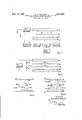
FIGURE 1 is a schematic diagram of one form of the invention;
- 3 FIGURE 2 is a schematic diagram of another form of the invention;
FIGURE 3 is a schematic diagram illustrating the effect of an electric field applied Only between the powder supply and stencil screen; and
FIGURE 4 is a schematic diagram illustrating the effect of an electric field applied between supply and screen and a second electric field applied between screen and article surface.
In FIGURE 1, there is disclosed a preferred embodiment of the invention in diagrammatic form. A supply of printing powder particles indicated at 10 is loosely piled in a layer of substantially uniform thickness upon the surface of an electrically conductive plate 12. A coated wire mesh stencil screen 14 is supported in spaced relationship above the surface of powder supply 10 and in spaced relationship below the surface of an article to be decorated, illustrated schematically at 16.
Transfer of particles from supply 10 to the surface of article 16 is accomplished by applying electric potentials to plate 12, screen 14 and article 16 to establish an electric field which is operable to electrically charge particles in supply 10 by virtue of their association with plate 12, and electrically impel the particles upwardly from supply 10 through openings 18 in screen 14 to the lower surface of article 16.
Many compositions of printing powder or powdered ink suitable for use in the arrangement of FIGURE 1 are presently commercially available. The exact composition of the powder employed is dependent upon the desired color, characteristics of the surface to be printed, desired image thickness or density, the type of decoration or printing desired, the electrical properties, and other variable factors. The powder employed must, of course, be capable of being electrically charged and of a particle size such that it can easily pass through the mesh of the stencil screen.
In an exemplary operation of the process illustrated in FIGURE 1, a loose layer approximately of an inch thick of a glass frit powder was supported upon plate 12. The frit particles were of a particle size range between 2 and 10 microns, as measured by a Coulter counter or other standard particle size measuring technique. The size range of 2 to 10 microns was preferable when used with the specific screen size described below, although an acceptable size range could have extended from 1 to 50 microns.
The electrical properties of the powder are most conveniently referenced in terms of its electrical resistivity. In the particular example, the resistivity of the powder was between 10 and ohm centimeters, as measured by a standard cylindrical cell technique. In measuring resistivity by the standard cylindrical cell technique, the powder to be measured is poured into a cylindrical container of electrical insulating material to form an unpacked cylindrical body of known cross sectional area and axial length. The unpacked powder is then compressed by reducing its axial length by a known amount and the electrical resistance of the packed cylindrical powder body is then measured by applying an electrical potential across its axial length.
Powder resistivities of between 10 to 10 ohm centimeters, as measured by the above technique, have proven satisfactory. Powders having a higher resistivity may require precharging by corona or triboelectrification techniques, in which case the polarity of the electric field must be oriented in accordance with the polarity of the charge on the particles.
With a printing powder having the foregoing characteristics, a stencil screen 14 of #200 mesh steel wire was employed. The openings in a #200 mesh screen are of the order of fifty times or more the size of particles within the size range referred to above. It is desirable that the screen mesh be larger than the maximum particle size by an order of between 10 and 100, so that bridging or clogging of the mesh openings is avoided. Within the foregoing limitations, a relatively fine mesh is desirable, in order to achieve as uniform a field density as possible over the area of the image apertures.
The spacing between plate 12 and screen 14, and between screen 14 and the article surface 16, will usually be of the order of A to A of an inch and 0.002 to 0.060 of an inch, respectively. The precise spacing is critical primarily in its relationship to the electric potential applied across the spacing, in that the electric field strength is of primary concern, and electric field strength is measured in volts per unit distance of spacing. For uniformity of the electric field, it is necessary that the spacing be uniform.
As indicated in the electric diagram of FIGURE 1, relatively high voltage is applied across the space between plate 12 and screen 14, while the article surface 16 is held at a relatively low voltage with respect to the screen, the potentials at plate 12 and article 16 being of opposite polarity. In the specific example partially described above, the output of the respective high voltage and low voltage supplies schematically shown in FIGURE 1 are such that an electric field having a field strength of between 60 and volts per mil exists between plate 12. and screen 14 and an electric field of between 10 and 25 volts per mil exists between screen 14 and article 16.
Experience has shown that good quality transfer of powder from supply 10 to article 16 in the indicated arrangement can be obtained using either synchronized AC or DC voltage sources, but a DC source is preferred. The movement of charged particles from plate '12 to the surface of article 16 is analogous to a flow of electric current, in that each particle receives an electric charge from plate 12 and carries this charge to the article 16. Where a powder bed approximately 4 inches square is employed, the voltage source should have sufficient power to supply at least 'rnilliampere of current during the powder transfer, this current being occasioned by the flow of charged particles described above. Satisfactory images are achieved by applying a potential pulse through the indicated circuitry of FIGURE 1 for a time duration of approximately 25 to 300 milliseconds. The longer the pulse, the thicker the imagine applied to article 16.
A convenient arrangement for applying pulses is illustrated in FIGURE 1 in which a controlled gate connects the output of an oscillator to a power amplifier for the desired pulse interval. The ouput of the power amplifier is fed into a high voltage transformer and rectifier whose output in turn is connected across plate 12 and screen 14. When a DC voltage is applied, it is applied in the form of a pulsating DC, in order to pass through the transformer.
In the disclosed arrangement of FIGURE, 1, good quality transfer of powder particles has been achieved with electric field strengths of the magnitudes described above. A good quality transfer may be defined as one in which the powder particles are packed in a thin layer of uniform density on the surface of article 16 with a high degree of r,esolution, or image sharpness. In order to achieve thisresult, retransfer. and scattering of particles during the transfer must be minimized.
Retransfer is, believed to occur when a powder particle which, for the sake of example, will be said to be positively-charged,- contacts an article surface which is itself charged to a negative potential. Uponcontact with the negatively. charged surface, the particle may loseits positive charge and become. negatively charged and thus electrically'repelledfrom the negatively charged surface. Experience has shownthat under. certain conditions, multiple transfers can occur within a relatively short time interval in which a particle may travel back and forth between supply and article -16 several times. The reversal of charge upon the particle upon contact with a charged surface does not necessarily occur instantaneously and, under some conditions, it has been observed that the image on the article surface is more dense during early stages of the transfer than in the later stages.
In an attempt to minimize the retransfer problem, the arrangement of FIGURE 1 has been tried with the low voltage supply to the article 16 disconnected. Disconnecting article surface 16 from a voltage source results in an electric field configuration of the type schematically illustrated in FIGURE 3, in which the electric lines of force extend from the surface of plate 12 to the individual wires 14a of screen 14 in the manner indicated at B. By applying a potential difference between plate 12 and wires 14a of sufficient magnitude, powder particles resting upon plate 12 can be accelerated to velocities high enough so that their momentum carries them clear and beyond the screen to the article surface.
With the electric field existing only between plate 12 and screen 14, scattering and lack of resolution in the resultant image on article 16 are observed. This is believed to be due to at least two effects, one of which is schematically indicated in FIGURE 3. Because the electric lines of force curve toward the individual wires 14a of the screen, the particles do not travel in straight-line motion, but follow a curved path such as a typical path illustrated by the dotted line P in FIGURE 3, thus, resulting in fuzziness along the image edges.
A second effect detrimental to image resolution where only a plate-to-screen field is applied occurs because the lack of positive guidance of particles in transit between the screen and article surface makes the particles susceptible to turbulent air currents generated by the simultaneous transit of a large number of particles through a given air space.
When, in addition to the establishment of an electric field between plate 12 and screen 14, a second field is established between screen 14 and the article surface, an electric field configuration somewhat similar to that schematically illustrated in FIGURE 4 exists. The first electric field extends between plate 12 and the individual wires 14a of the screen, as in the FIGURE 3 arrangement, the electric lines of force of the first field being indicated at E1 in FIGURE 4, while a second series of lines of force E2 extend from the individual Wires 14a to the article surface.
A typical particle path is illustrated in dotted lines at P1 in FIGURE 4, and it will be observed that, although the particle is deflected somewhat toward the nearest screen wire 14a as it leaves the lower field, the orientation of the lines of force E2 of the upper field tend to deflect the particle back toward vertical alignment with the point from which it left plate 12.
The provision of an upper field between the screen and article surface is thus desirable to counteract the field distortion present in the lower field by virtue of the ar-. rangement of the individual screen wires 14a, and to tounteract the aerodynamic effects present. At the same time, it is desirable to keep article surface 16 at a relatively low potential in order to minimize retransfer effects. v v
It has been found that the most efficient method of transferring particles from a supply such as 10 in FIG- URE 1, isto apply electric fieldsbothabove and below screen 14 to perform t-woseparate functions. The lower field between plate -12 and screen 14 isassigned the functionof electrically charging and accelerating powder particlesfrom supply 10 upwardly. through the image apertures 18 of screen 14, while .the field between screen 14 and article 16 is assigned the function of merely guiding or focusing the particles upon the article surface.
To perform their respective functions, the lower or particle accelerating field is preferably made of as high a field strength as possible without reaching the breakdown point of the dielectric medium-air in the usual case. It has been found that breakdown, or sparking, in an air environment begins to occur at field strengths over volts per mil. For transfer of a glass frit, such as in the specific example described above, a minimum or threshold field strength of the field between plate 12 and screen 14 of 30 to 35 volts per mil has been found to be the minimum strength necessary for satisfactory operation.
The lower or accelerating field strength should be sufficient to electrically charge particles in the supply and impel the particles through the screen with sufficient velocity to impinge on the article surface, even in the absence of an upper field.
Experience has shown that upper field strengths between screen 14 and the article surface over 25 volts per mil result in an undesirable amount of retransfer, and the upper field strength is preferably maintained below this figure.
The upper field strength should be as high as possible to enable this field to perform its particle guiding or focusing function without being so high as to cause retransfer problems.
In FIGURE 2, an alternative form of the invention is disclosed which, in essence, differs from the FIGURE 1 embodiment in that the electrical focusing action referred to above is further augmented by the employment of a second mechanical focusing or collimating screen 20 which is located between an electrically conductive screen 22 and the article 24 being decorated. As in the previous case, an electrically conductive plate 26 is employed to support a supply of printing powder particles indicated at 28, the supply, screens and articles all being maintained in a spaced relationship to each other. A common, high voltage source is connected across article 24, screen 22 and plate 26 by variable voltage dividing resistances R1 and R2 which may be adjusted as desired to proportion the voltage drop between the plate and screen, and between the screen and article.
Collimating or focusing screen 20 is preferably of a non-conductive material and, in fact, may consist of a sheet of cardboard or the like having openings 29 cut to match the image-defining apertures 30 of the conductive screen.
It will be noted that with the electrical connections of FIGURE 2, the respective voltage drops on either side of screen 22 are proportional and that the total voltage drop between plates 26 and article 24 is constant. By proportioning the voltage division, the potential of screen 22 relative to the plate and article surface can be adjusted and the respective electric field strength regulated by varying the spacing between the various elements.
While various embodiments of the invention have been described, it will be apparent to those skilled in the art that the disclosed embodiments may be modified. Therefore, the foregoing description is to be considered exemplary rather than limiting, and the true scope of the invention is that defined in the following claims.
I claim:
1. The method of applying a layer of powder particles to an article surface in a predetermined pattern comprising the steps of supporting a bed of powder particles capable of being electrically charged at one side of an electrically conductive element, locating in spaced relationship from the opposite side of said bed of particles an electrically conductive wire mesh screen having a coated first portion wherein the mesh openings are filled with said coating and an uncoated second portion having a shape corresponding to the predetermined pattern of the powder layer to be applied to the article surface, locating the article surface to which the powder layer is to be applied in spaced relationship from said screen at the side of said screen remote from said bed, applying a first electric field between said conductive element and said wire mesh screen having a field strength sufiicient to electrically charge and impel particles from said supply through the uncoated portion of said wire mesh screen to said article surface, and simultaneously applying a second electric field between said wire mesh screen and said article surface having a field strength substantially less than the field strength of said first electric field to exert a guiding action on particles in transit between said screen and article surface to confine the areas of impingement of said particles on said article surface to areas corresponding to the uncoated second portion of said wire mesh screen.
2. The method as defined in claim 1 wherein the field strength of said first electric field is at least 35 voltsper mil and the field strength of said second electric field is less than 25 volts per mil.
3. The method as defined in claim 2 wherein said first electric field is applied by connecting a source of electric potential between said conductive element and said screen for a period of time within the range of 25 and 300 milliseconds.
4. The method as defined in claim 1 wherein the bed of powder particles is supported vertically above the electrically conductive element, and the electrically conductive wire mesh screen is vertically spaced above said bed of powder.
5. The method of applying a layer of powder particles to an article surface in a predetermined pattern comprising the steps of supporting a bed of powder particles capable of being electrically charged above an electrically conductive element, locating in spaced relationship above said bed of particles an electrically conductive wire mesh screen having a coated first portion wherein the mesh openings are filled with said coating and an uncoated second portion having a shape corresponding to the predetermined pattern of the powder layer to be applied to the article surface, locating the article surface to which the powder layer is to be applied in spaced relationship above said screen, applying a first electric field between said conductive element and said wire mesh screen having a field strength sufficient to electrically charge and impel particles from said supply through the uncoated portion of said wire mesh screen to said article surface, and simultaneously applying a second electric field between said wire mesh screen and said article surface having a field strength substantially less than the field strength of said first electric field to exert a guiding action on particles in transit between said screen and article surface to confine theareas of impingement of said particles on said article surface to areas corresponding to the uncoated second portion of said wire mesh screen.
6. The method as defined in claim 5 whereinthe field strength of said first electric field is at least 35 volts per mil and the field strength of said second electric field is less than 25 volts per mil.
7. The method as defined in claim 6 wherein said first electric field is applied by connecting a source of electric potential between said conductive element and said screen for a period of time within the range of 25 and 300 milliseconds.
8. The method of applying a layer of powder particles to an article surface in a predetermined pattern comprising the steps of: supporting a bed of powder particles capable of being electrically charged by an electrically conductive element, located in spaced relationship to said bed of particles an electrically conductive wire mesh screen having a coated first portion wherein the mesh openings are filled with said coating and an uncoated second portion having a shape corresponding to the predetermined pattern of the powder layer to be applied to the article surface, locating the article surface to which the powder layer is to be applied in spaced relationship with said screen, applying a first electric field between said conductive element and said wire mesh screen'having a field strength sufficient to electrically charge and impel particles from said supply through the uncoated portion of said wire mesh screen to said article surface, and simultaneously applying a second electric field between said wire mesh screen and said article surface having a field strength substantially less than the field strength of said first electric field to exert a guiding action on particles in transit between said screen and article surface to confine the areas of impingement of said particles on said article surface to areas corresponding to the uncoated second portion of said wire mesh screen.
9. The method as defined in claim 8 wherein the field strength of said first electric field is at least 35 volts per mil and the field strength of said second electric field is less than 25 volts per mil, and said first electric field 1s applied by connecting a source of electric potential between said conductive element and said screen for a period of time within the range of 25 and 300 milliseconds.
References Cited UNITED STATES PATENTS 2,787,556 4/1957 Haas.
2,940,864 6/1960 Watson.
3,218,968 11/1965 Childress et a1.
3,245,341 4/1966 Childressetal.
3,253,540 5/1966 Lusher.
3,285,167 11/1966 Childress et al. 101-114 3,294,017 12/1966 St. John 101-114 3,295,440 1/1967 Rarey etal. 3,301,179 1/1967 Johnson 101-114 3,306,193 2/1967 Rarey et al. 101 114 3,307,477 3/1967 Booker.
3,081,698 3/1963 Childress et al. 101-429 3,321,768 5/1967 Byrd 346-74 FOREIGN PATENTS 81,920 9/1956 Denmark.
ROBERT E. PULFREY, Primary Examiner. E. S. BURR, Assistant Examiner.
Priority Applications (1)
| Application Number | Priority Date | Filing Date | Title |
|---|---|---|---|
| US575868A US3402659A (en) | 1966-08-29 | 1966-08-29 | Electrical printing processes employing two fields of different strengths |
Applications Claiming Priority (1)
| Application Number | Priority Date | Filing Date | Title |
|---|---|---|---|
| US575868A US3402659A (en) | 1966-08-29 | 1966-08-29 | Electrical printing processes employing two fields of different strengths |
Publications (1)
| Publication Number | Publication Date |
|---|---|
| US3402659A true US3402659A (en) | 1968-09-24 |
Family
ID=24302023
Family Applications (1)
| Application Number | Title | Priority Date | Filing Date |
|---|---|---|---|
| US575868A Expired - Lifetime US3402659A (en) | 1966-08-29 | 1966-08-29 | Electrical printing processes employing two fields of different strengths |
Country Status (1)
| Country | Link |
|---|---|
| US (1) | US3402659A (en) |
Cited By (2)
| Publication number | Priority date | Publication date | Assignee | Title |
|---|---|---|---|---|
| US3526500A (en) * | 1966-10-05 | 1970-09-01 | Owens Illinois Inc | Process of electrostatic printing by projecting electrically photosensitive particles through an image-defining screen |
| US20200094602A1 (en) * | 2018-09-25 | 2020-03-26 | Kyocera Document Solutions Inc. | Laser Ablation Printing |
Citations (13)
| Publication number | Priority date | Publication date | Assignee | Title |
|---|---|---|---|---|
| US2787556A (en) * | 1955-11-23 | 1957-04-02 | Sylvania Electric Prod | Image reproduction device screen forming process |
| US2940864A (en) * | 1954-03-24 | 1960-06-14 | Sylvania Electric Prod | Method of preparing a fluorescent screen |
| US3081698A (en) * | 1960-03-04 | 1963-03-19 | Electrostatic Printing Corp | Electrostatic printing system |
| US3218968A (en) * | 1962-12-17 | 1965-11-23 | Electrostatic Printing Corp | Multicolor electrostatic printing |
| US3245341A (en) * | 1963-04-15 | 1966-04-12 | Electrostatic Printing Corp | Powder image forming device |
| US3253540A (en) * | 1963-04-19 | 1966-05-31 | Owens Illinois Glass Co | Method of printing |
| US3285167A (en) * | 1963-10-04 | 1966-11-15 | Crocker Citizens Nat Bank | Electrostatic printing system with controlled powder feed |
| US3294017A (en) * | 1964-10-19 | 1966-12-27 | Owens Illinois Inc | Process and apparatus for electrostatically printing on hot substrate |
| US3295440A (en) * | 1964-05-27 | 1967-01-03 | Continental Can Co | Electrostatic printing method and apparatus employing corona discharge means |
| US3301179A (en) * | 1965-03-15 | 1967-01-31 | Owens Illinois Inc | Electrostatic printing with density control provided by charge measuring means |
| US3306193A (en) * | 1964-09-14 | 1967-02-28 | Continental Can Co | Electrostatic screen printing with magnetic conveyer and moving base electrode |
| US3307477A (en) * | 1964-09-25 | 1967-03-07 | Owens Illinois Inc | Electrical printing using stencil and moving slot powder metering means |
| US3321768A (en) * | 1960-05-12 | 1967-05-23 | Burroughs Corp | Electrostatic recording with interchangeable stencils |
-
1966
- 1966-08-29 US US575868A patent/US3402659A/en not_active Expired - Lifetime
Patent Citations (13)
| Publication number | Priority date | Publication date | Assignee | Title |
|---|---|---|---|---|
| US2940864A (en) * | 1954-03-24 | 1960-06-14 | Sylvania Electric Prod | Method of preparing a fluorescent screen |
| US2787556A (en) * | 1955-11-23 | 1957-04-02 | Sylvania Electric Prod | Image reproduction device screen forming process |
| US3081698A (en) * | 1960-03-04 | 1963-03-19 | Electrostatic Printing Corp | Electrostatic printing system |
| US3321768A (en) * | 1960-05-12 | 1967-05-23 | Burroughs Corp | Electrostatic recording with interchangeable stencils |
| US3218968A (en) * | 1962-12-17 | 1965-11-23 | Electrostatic Printing Corp | Multicolor electrostatic printing |
| US3245341A (en) * | 1963-04-15 | 1966-04-12 | Electrostatic Printing Corp | Powder image forming device |
| US3253540A (en) * | 1963-04-19 | 1966-05-31 | Owens Illinois Glass Co | Method of printing |
| US3285167A (en) * | 1963-10-04 | 1966-11-15 | Crocker Citizens Nat Bank | Electrostatic printing system with controlled powder feed |
| US3295440A (en) * | 1964-05-27 | 1967-01-03 | Continental Can Co | Electrostatic printing method and apparatus employing corona discharge means |
| US3306193A (en) * | 1964-09-14 | 1967-02-28 | Continental Can Co | Electrostatic screen printing with magnetic conveyer and moving base electrode |
| US3307477A (en) * | 1964-09-25 | 1967-03-07 | Owens Illinois Inc | Electrical printing using stencil and moving slot powder metering means |
| US3294017A (en) * | 1964-10-19 | 1966-12-27 | Owens Illinois Inc | Process and apparatus for electrostatically printing on hot substrate |
| US3301179A (en) * | 1965-03-15 | 1967-01-31 | Owens Illinois Inc | Electrostatic printing with density control provided by charge measuring means |
Cited By (3)
| Publication number | Priority date | Publication date | Assignee | Title |
|---|---|---|---|---|
| US3526500A (en) * | 1966-10-05 | 1970-09-01 | Owens Illinois Inc | Process of electrostatic printing by projecting electrically photosensitive particles through an image-defining screen |
| US20200094602A1 (en) * | 2018-09-25 | 2020-03-26 | Kyocera Document Solutions Inc. | Laser Ablation Printing |
| US10682875B2 (en) * | 2018-09-25 | 2020-06-16 | Kyocera Document Solutions Inc. | Laser ablation printing |
Similar Documents
| Publication | Publication Date | Title |
|---|---|---|
| US4088093A (en) | Web coating and powder feed | |
| US3295440A (en) | Electrostatic printing method and apparatus employing corona discharge means | |
| US3656171A (en) | Apparatus and method for sorting particles and jet prop recording | |
| DE68917279T2 (en) | Electrostatic pressure device. | |
| DE69006949T2 (en) | Electrostatic pressure device. | |
| US3306193A (en) | Electrostatic screen printing with magnetic conveyer and moving base electrode | |
| US3680779A (en) | Method and apparatus for electrostatic spraying | |
| US3081698A (en) | Electrostatic printing system | |
| US3798048A (en) | Method and apparatus for electrostatically coating an object | |
| US4155093A (en) | Method and apparatus for generating charged particles | |
| DE69118862T2 (en) | Apparatus and method for applying a non-magnetic and non-conductive toner | |
| US5817374A (en) | Process for patterning powders into thick layers | |
| DE69627335T2 (en) | APPARATUS AND METHOD FOR FEEDING MATERIAL INTO A SUBSTRATE | |
| GB1027438A (en) | Improvements in electrostatic printing | |
| US4427712A (en) | Electrodynamic coating process | |
| US3285167A (en) | Electrostatic printing system with controlled powder feed | |
| DE1808146B2 (en) | Electrographic printing process and pigment for its implementation | |
| US3521558A (en) | Electrostatic printing with potential control | |
| GB1573106A (en) | Method and apparatus for manufacturing fusible interlinings | |
| US3402659A (en) | Electrical printing processes employing two fields of different strengths | |
| DE1227484B (en) | Method of forming an image on an insulating sheet and apparatus for carrying out the method | |
| US3296963A (en) | Electrostatic screen printing of articles made of highly insulating materials | |
| JPH0330848A (en) | Method and apparatus for electrostatic spray of liquid | |
| US3635157A (en) | Method and apparatus for electrostatically charging particles for printing or coating | |
| DE10163025A1 (en) | Method and device for coating moving substrates |