US3361879A - Disconnect switch - Google Patents
Disconnect switch Download PDFInfo
- Publication number
- US3361879A US3361879A US562826A US56282666A US3361879A US 3361879 A US3361879 A US 3361879A US 562826 A US562826 A US 562826A US 56282666 A US56282666 A US 56282666A US 3361879 A US3361879 A US 3361879A
- Authority
- US
- United States
- Prior art keywords
- blade
- carriage
- switch
- hinge
- movement
- Prior art date
- Legal status (The legal status is an assumption and is not a legal conclusion. Google has not performed a legal analysis and makes no representation as to the accuracy of the status listed.)
- Expired - Lifetime
Links
Images


Classifications
-
- H—ELECTRICITY
- H01—ELECTRIC ELEMENTS
- H01H—ELECTRIC SWITCHES; RELAYS; SELECTORS; EMERGENCY PROTECTIVE DEVICES
- H01H3/00—Mechanisms for operating contacts
- H01H3/32—Driving mechanisms, i.e. for transmitting driving force to the contacts
- H01H3/40—Driving mechanisms, i.e. for transmitting driving force to the contacts using friction, toothed, or screw-and-nut gearing
-
- H—ELECTRICITY
- H01—ELECTRIC ELEMENTS
- H01H—ELECTRIC SWITCHES; RELAYS; SELECTORS; EMERGENCY PROTECTIVE DEVICES
- H01H31/00—Air-break switches for high tension without arc-extinguishing or arc-preventing means
- H01H31/26—Air-break switches for high tension without arc-extinguishing or arc-preventing means with movable contact that remains electrically connected to one line in open position of switch
- H01H31/28—Air-break switches for high tension without arc-extinguishing or arc-preventing means with movable contact that remains electrically connected to one line in open position of switch with angularly-movable contact
-
- H—ELECTRICITY
- H01—ELECTRIC ELEMENTS
- H01H—ELECTRIC SWITCHES; RELAYS; SELECTORS; EMERGENCY PROTECTIVE DEVICES
- H01H33/00—High-tension or heavy-current switches with arc-extinguishing or arc-preventing means
- H01H33/02—Details
- H01H33/28—Power arrangements internal to the switch for operating the driving mechanism
- H01H33/36—Power arrangements internal to the switch for operating the driving mechanism using dynamo-electric motor
-
- H—ELECTRICITY
- H01—ELECTRIC ELEMENTS
- H01H—ELECTRIC SWITCHES; RELAYS; SELECTORS; EMERGENCY PROTECTIVE DEVICES
- H01H31/00—Air-break switches for high tension without arc-extinguishing or arc-preventing means
- H01H31/26—Air-break switches for high tension without arc-extinguishing or arc-preventing means with movable contact that remains electrically connected to one line in open position of switch
- H01H31/28—Air-break switches for high tension without arc-extinguishing or arc-preventing means with movable contact that remains electrically connected to one line in open position of switch with angularly-movable contact
- H01H2031/286—Air-break switches for high tension without arc-extinguishing or arc-preventing means with movable contact that remains electrically connected to one line in open position of switch with angularly-movable contact wherein the contact is rotatable around its own longitudinal axis
Definitions
- the present invention relates to high tension electric switch gear, and particularly, to improvements in disconnect switches of the type including a blade that is pivotally movable toward and away from the switch contacts and that is rotatable about its own axis into and out of high pressure engagement with the contacts.
- the primary objectives of the invention are the provision of an improved switch of the character described that (a) is comprised of only two insulator stacks rather than the three previously required; (b) embodies improved means for controlling the rotary and pivotal movements of the blade, specifically for causing said movements to occur sequentially at the times proper for optimum switch performance; (c) is positive in actuation; (d) embodies means for positively locking the switch blade in its closed and open positions; and (e) is fluid pressure operated.
- FIGURE 1 is a side elevation of the preferred embodiment of my improved switch showing the blade thereof in closed position in solid lines and in open position in dotted lines;
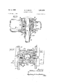
- FIGURE 2 is a cross-sectional view taken substantially on line 2-2 of FIGURE 1, but on an enlarged scale;
- FIGURE 3 is a fragmentary horizontal longitudinal section taken substantially on line 3-3 of FIGURE 2;
- FIGURE 4 is a fragmentary vertical section taken substantially on line 4-4 of FIGURE 2, the blade being shown in closed, locked position in solid lines and in closed, unlocked position in dotted lines;
- FIGURE 5 is a fragmentary cross-sectional view taken substantially on line 5-5 of FIGURE 4, but on a further enlarged scale, and showing the mechanism in blade closed, locked position;
- FIGURE 6 is a view similar to FIGURE 5 showing the mechanism in blade closed but unlocked positions
- FIGURE 7 is a view like FIGURE 4 but showing the blade in open position
- FIGURE 8 is a view similar to FIGURE 5 but taken substantially on line 88 of FIGURE 7 and showing the mechanism in blade open but unlocked position;
- FIGURE 9 is a view similar to FIGURE 8 showing the mechanism in blade open, locked position.
- the switch is shown as consisting essentially of a base 20, a pair of stationary insulator stacks 21 and 22 projecting in spaced parallel relation to one another from adjacent the opposite ends of the base, a stationary contact and terminal pad structure 23 on the outer end of stack 21, a second contact structure 24 on the outer end of stack 22, a blade operating mechanism 25 carried entirely by the one stack 22, and a switch blade 26 carried and driven by the mechanism 25 for pivotal movement about an axis transverse thereto from the switch closed position shown in solid lines to the switch open position shown in dotted lines.
- the mechanism 25 rotates the switch blade about its own axis to cause the blade to move into and out of 3,361,879 Patented Jan. 2, 1968 high pressure small area engagement with at least the contact 23.
- the contact 23, as viewed in end elevation, is of generally U-shaped configuration comprising one or more pairs of transversely spaced spring biased contact fingers 27.
- the outer end of the blade 26 is flattened to form a beaver tail end portion 28 having a first transverse dimension less than the normal spacing between the fingers 27 and a second transverse dimension greater than the normal spacing of said fingers.
- the object is to move the beaver tail end of the blade into the contact with the small dimension thereof entering freely between the fingers, and thereafter to rotate the blade to disposed the broad dimension of the tail perpendicular to the fingers to cause the same to have high pressure small area contact with the fingers.
- the object Upon opening movement of the blade, the object is to first rotate the blade to relieve the high pressure contact engagement (which rotary movement is also especially effective to break ice accumulating on the blade and contact if the switch is installed outdoors in freezing climates) and thereafter to pivot the blade out of the contact.
- This same arrangement, or modifications thereof, may also be applied in respect of the contact 24 and the portion of the blade engaging therein.
- the blade operating mechanism comprises a frame 30 fixedly secured to the outer end of the insulator 22.
- the frame is suitably U-shaped, as shown in FIGURE 2, and includes spaced upstanding side plates 31 paralleling the blade.
- a blade hinge 32 Pivotally mounted between the side plates is a blade hinge 32 which preferably is in the form essentially of a sleeve concentric with the blade.
- the hinge is mounted on the frame plates by a pivot pin 33 and a shaft 34 which extend into opposed wall portions of the sleeve on a pivot axis transverse to the blade.
- the pivot pin 33 is secured to the hinge 32, journalled in the adjacent plate 31 and coupled to a conventional blade counterbalancing device 35 which is mounted on the outboard side of the respective plate; and the shaft 34 comprises the drive shaft of a motor 36 mounted on the outboard side of the other plate 31 and extended through the plate and into guiding association with hinge 32.
- a conventional blade counterbalancing device 35 which is mounted on the outboard side of the respective plate
- the shaft 34 comprises the drive shaft of a motor 36 mounted on the outboard side of the other plate 31 and extended through the plate and into guiding association with hinge 32.
- Other pivot mountings for the hinge may be provided within the skill of the art and the counterbalance device may be omitted if desired, especially in the smaller switch ratings.
- a blade carriage 37 also comprising a sleeve, is journalled concentrically in the sleeve forming the hinge 32.
- the carriage is provided at one end with a radially extending flange opposed to the adjacent end of the hinge and a shoulder portion opposed to a bevelled portion of the hinge and forming therewith a raceway for an annular series of bearing balls 38.
- the carriage is provided with a threaded stem for reception of a nut 39, which together with an opposed bevelled surface on the hinge forms a raceway for a second annular series of the bearing balls 38, whereby the carriage is mOunted on the hinge for free rotary movement therein.
- the blade 26 extends axially into and through the carriage 37 and is suitably secured to the carriage as by means of a bolt 40 extending radially through the carriage into the blade.
- the blade is thus mounted by the carriage for rotation about the axis of the carriage, and is mounted by the carriage and hinge for pivotal movement about the axis of the pivot pins 33-34.
- the axis of the blade is coincident with the axis of the carriage, and the axes of the blade, the hinge pivot and the insulator stack, in the closed position of the blade, all extend at right angles to one another and intersect at a common point on the axis of the blade.
- the switch is similar in principle and mode of operation to a number of prior art switches, such for example, as Fjellstedt 2,23 1,992 and 2,527,924; with the notable exceptions of the presence of only two insulator stacks and the motor 36.
- the blade hinge 32 is provided with interlock means comprised of at least one and preferably two lock bolts or bars 41a and 41b.
- the bars extend parallel to the pivot axis of the hinge in the plane of said axis to opposite sides of the blade carriage, and each is of a length equal approximately to the transverse dimension of the hinge and also the transverse spacing between the plates 31.
- the bars m-ove oppositely of one another and one of the plates 31 is provided with a hole or aperture 4251c aligned with the bar 41:: in the closed position of the switch and a second hole or aperture 42b0 spaced arcuately from the hole ilac relative to the pivot axis of the hinge and disposed to be aligned with the bar 4112 in the open position of the switch.
- the other of the plates 31 provided with arcuately spaced holes 4212c and 42:20 aligned respectively with the bar 4111 in the closed position of the switch and with the bar 41a in the open position of the switch.
- the bars or bolts 41 are suitably of square or other noncircular configuration and are slidably mounted in complemental transverse bores in the hinge 32 for reciprocable but non-rotary movement therein.
- the bores are open at the opposite ends thereof to communicate with the plates 31, and the lock bolts are extendible from the opposite ends of the bores to accommodate entry of the bolts 41a and 4112 into the holes 4211c and 42bc in the closed position of the switch and into the holes 42410 and 42b0 in the open position of the switch.
- each plate 31 is imperforate, and the holes in the plates are staggered circumferentially as shown in FIGURES 4 and 7, whereby the imperforate surfaces of the two plates form and constitute detent means controlling movement of the two bars.
- each of the bars or bolts 41 is provided with a rack tooth formation 43 of limited extent, and the bars are so mounted in the hinge that the tooth formations project through openings in the wall of the hinge into the interior or central bore thereof.
- the blade carriage 37 is provided with driver means for operating the two bolts 41.
- t-he carriage is provided with a peripheral surface portion 44 having a pair of diametrically opposed pinion tooth formations 45 thereon for co-operation with the rack tooth formations on the two bars.
- the diametrical line of the formations 45 is preferably offset from the major transverse dimension of the blade end by a few degrees.
- the two sets of tooth formations 43 and 45 are such that they may be engaged and disengaged at selected times during operation of the switch, and in particular disengaged subsequent to locking the bolts or bars 41 in the respective lock holes thereby to accommodate rotary over-travel of the blade to dispose the blade end in desired position and engaged for simultaneous movement of the carriage and the bolts during and immediately prior and subsequent to pivotal movement of the blade, carriage and binge.
- each pinion tooth formation 45 comprises full tooth 46, a pair of half-tooth recesses 47 to opposite sides of the full tooth and surfaces 48 to opposite sides of said recesses formed on the pitch line of the tooth.
- the entire surface of the portion 44 of the carriage, other than the teeth and tooth recesses, is formed on the pitch circle of the two teeth.
- each rack-tooth formation 43 comprises a complemental full tooth recess 49 centrally of the respective bar, a pair of half-teeth 50 to opposite sides of said recess and surfaces 51 to opposite sides of said half-teeth formed on the pitch line of the tooth recess.
- Each of pitch line surfaces 51 is preferably of only such extent as to receive the complemental segment of the adjacent pitch line surface 48 of the pinion tooth formations when the two sets of formations are disengaged as shown in FIGURE 5.
- a bolt or bar locking action is defined by the pitch line surfaces, the teeth 50 on each bar preventing movement in one direction and the end of the surface 51 engaged by the carriage preventing movement in the other direction, whereby each bar is positively locked against movement in the positions in which it locks the hinge to the frame.
- the radial flange at the forward end of the carriage 37 is provided at the periphery thereof with a bevel gear formation 52 in the form suitably of a gear segment of about 225 degrees arcuate extent.
- a second bevel gear 54 Meshed with the gear 52 is a second bevel gear 54 of substantially the same structure, the gear 54 extending at right angles to the flange gear 52 into a space between the hinge 32 and the adjacent side plate 31 and being mounted concentrically on the shaft 34 of the motor 36,
- the motor 36 is reversible and adapted to be operated in one direction to open the switch and in the other direction to close the switch.
- the gear 54 is thus rotated in opposite directions by the motor, and the same is freely rotatable relative to the frame and the hinge to transmit movement to the flange gear 52.
- the gear 54 has appropriately positioned arcuate slots 55 therein to avoid interference between the same and the lock bolts 41.
- the positions of the described components of the mechanism 25 are as illustrated in FIGURE 5 and the beaver tail end 28 of the blade is transverse to the contact structure to have high pressure engagement therewith.
- the bolt 41a is entered into hole 42:10 and the bolt 41b is entered into hole 4212c, whereby the blade is positively locked in closed position.
- the two bolts in turn are positively locked in their positions by the pitch line locks between the same and the surfaces 48 of the iade carriage.
- the motor 36 is energized to drive the gear 54 in such direction as to rotate the gear flange 52, and thus the blade carriage 37 and blade 26, in a counterclockwise direction as viewed in FIGURE 5.
- the hinge 32 is locked against pivotal movement by the bars 41, and the motor is thus compelled to rotate the carriage and the blade, and specifically to effect only rotary movement of the blade.
- Initial blade rotation is through an arc of about degrees, during which time the beaver tail 2% is rotated from a position transverse to the contact structure 23 (as shown in FIGURE 5) to a position parallel to such structure (as shown in FIGURE 6), thereby to relieve the high pressure engagement of the blade in the contact, and in fact, to completely free the blade from the contact.
- Such movement is governed by the hinge pivot means which is coincident with the axis of gear 54, whereby the gears 52 and 54 remain meshed and the assembly of blade, carriage and binge is pivoted upwardly from blade closed to blade open position as shown in FIGURE 1, and also in the comparison of FIGURES 4 and 7.
- the bolts 41 engage detent surface areas of the respective plates 31, whereby the blade, carriage, hinge and bolts remain locked together as a unit.
- the arcuate extent of pivotal movement of the blade may vary widely, but I prefer to move the blade over center relative to its pivot axis so as to open a wide gap between the blade and the contact 23 and especially to place the blade in a position where its own weight tends to keep it open and to restrict natural or outside forces that might tend to urge it to closed position. For these reasons, I have provided for pivotal movement of about 105 degrees in the illustrated embodiment of the switch.
- the blade hinge 32 is provided with a rearward extension 56 and a co-operable stop pin 57 is extended from the frame plates at a location to be engaged by the extension 56 when the blade is fully opened, as shown in FIGURE 7.
- a closed position stop 58 is disposed on the frame for engagement by said extension in the closed position of the blade, as shown in FIGURE 4.
- the switch could be a double-throw switch having a contact structure at the open position of the blade, in which case the blade could have imparted to it over-travel of about 60 to 70 degrees (i.e., a total rotary movement of about 90 degrees in open position) to again move the blade end 28 into a position transverse to the contact structure.
- the gears 52 and 54 in the illustrated embodiment have an arcuate extent of 225 degrees (90 degrees initial rotation, 105 degrees pivotal movement and 30 degrees final rotation of the blade), there is no reason why this could not be more or less depending upon the objectives to be achieved.
- the arcuate extent of the gears could be 285 degrees for the purposes stated.
- Rotation of the gear 54 thus effects both rotation and pivotal movement of the switch blade and does so in a definite sequence of individual movements all positive in nature, whereby the blade is positively driven into and out of the contacts and into and out of locked relation thereto.
- the gear 54 may be driven in various manners, and it is a particular object to drive the gear by virtue of means mounted on and extending through the single insulator stack 22.
- the stack and the insulator elements thereof are hollow, as indicated in FIG- URE 1, and the drive means for the gear includes insulated means extending upwardly through the hollow insulator.
- the insulator may be charged with a suitable gas or liquid to maintain the insulating capacity thereof and shield and protect the insulated means therein.
- the drive means may take a variety of forms, such as a gear positioned on top the insulator coincident with the axis thereof, meshed with the gear 54 and driven via an insulated shaft by a motor or the like at the bottom of the stack.
- a gear positioned on top the insulator coincident with the axis thereof, meshed with the gear 54 and driven via an insulated shaft by a motor or the like at the bottom of the stack.
- the motor 36 is a reversible hydraulic motor removably mounted on the outer surface of one of the plates 31 of the frame 30, and the shaft 34 thereof is splined for quick connection with and disconnection from the gear 54, whereby the motor is readily assembled with the switch and is also readily replaced should it become defective.
- Hydraulic fluid under pressure is fed to and returned from the motor 36 via a pair of insulated conduits 60 which extend from the motor through the insulator and are connected via four-way valve (not shown) to a suitable hydraulic pump (not shown).
- the valve serves in one position thereof to cause supply of fluid via one conduit and return of fluid via the other conduit to drive the motor in one direction, and in its other position, to cause supply of fluid via said other conduit and return of fluid via said one conduit to drive the motor in the opposite direction.
- a switch having a frame, a blade hinge pivoted on said frame on a first axis, a blade carriage journalied in said hinge on a second axis and a blade carried by said carriage for rotation about said second axis and pivotal movement about said first axis between switch open and switch closed positions
- interlock means carried by said hinge and cooperative with said frame in the closed position of the blade for locking said hinge to the frame in said position
- driver means on said carriage engageable with said interlock means upon rotation of said carriage for driving the same in one direction to release said interlock means from the frame upon opening movement of the blade
- detent means between the closed and open positions of the switch for limiting movement of said interlock means in said one direction upon opening movement of the blade
- said interlock means and said driver means including means preventing relative movement thereof when said detent means limits movement of said interlock means whereby said carriage and said hinge are operatively connected for conjoint movement, and means for rotating said carriage about said second axis and pivoting the same about said first axis, said interlock means in
- interlock means also cooperating with said frame in the open position of the blade and being engaged therewith upon movement of said interlock means in said one direction whereby the blade is locked in both its closed and open positions by said interlock means.
- said means for rotating and pivoting said carriage being reversible, said interlock means being reversely movable and said detent means limiting movement of said interlock means in both directions between the closed and open positions of the blade, whereby the blade in moving from closed to open positions is first rotated to release said interlock means and then pivoted, and in moving from open to closed positions is pivoted to the closed position and then rotated to engage said interlock means.
- said means for rotating and pivoting said carriage being reversible, said interlock means being reversely removable, and said detent means limiting movement of said interlock means in both directions between the closed and open positions of the switch, whereby the blade in moving from closed to open positions is first rotated in one direction to release said interlock means, then pivoted to open position and then further rotated in said one direction to engage said interlock means and lock the blade in open position, and in moving from open to closed positions is first rotated in the opposite direction to release the interlock means, then pivoted to the closed position and then further rotated in said opposite direction to engage said interlock means and lock the blade in closed position.
- said interlock means comprising a bolt reciprocably mounted in the blade hinge.
- said blade hinge having a bore therethrough
- said interlock means comprising a bolt reciprocably mounted in said bore, said frame having holes in portions thereof spaced arcuately about said first axis, said bolt being aligned with one of said holes in the closed position of the blade and being aligned with the other of said holes in the open position of the blade, said detent means comprising shielding means closing the opposite ends of said bore in the areaate space between said holes.
- said interlock means comprising a bolt reciprocably mounted in said blade hinge in a plane transverse to said second axis and having a rack tooth formation facing toward the periphery of said carriage, said carriage including a peripheral surface contiguous to said bolt, said driver means comprising a pinion tooth formation on said surface engageable with said rack tooth formation for imparting reciprocable motion to said bolt, said tooth formations accommodating engagement thereof during the releasing and engaging movements of said interlock means and pivotal novement of the blade and accommodating disengagement thereof subsequent to engaging movement of said interlock means to accommodate rotary over travel of the carriage and the blade in closed and open positions of the blade.
- one of said tooth formations comprising a full tooth, a pair of half tooth recesses to opposite sides of the tooth and surfaces to opposite sides of said recesses formed along the pitch line of said tooth; the other of said tooth formations comprising a complemental full tooth recess, a pair of half teeth to opposite sides of said recess and surfaces to opposite sides of said teeth formed along the pitch line of said tooth recess; whereby said formations may engage and disengage and whereby a pitch line lock is formed between said pitch line surfaces upon disengagement of said formations accommodating rotation of said carriage but preventing movement of said bolt.
- said frame including a plate contiguous to said hinge and normal to said first axis, an aperture in said plate, a bore in said hinge parallel to said first axis communicating in said aperture in the closed position of the blade, said interlock means comprising a bolt reciprocable in said bore and extensible into said aperture for locking said hinge to said frame, the unapertured surfaces of said plate comprising said detent means.
- said frame including a pair of spaced parallel plates contiguous respectively to the opposite sides of said hinge in planes normal to said first axis, an aperture in each of said plates spaced arcuately from one another about said pivot axis, a through bore in said hinge parallel to said first axis, said bore communicating at one end with the aperture in one plate in the closed position of the blade and communicating at its other end with the aperture in the other plate in the open position of the blade, said interlock means comprising a bolt reciprocable in said bore and extensible from the opposite ends thereof into the respective apertures for locking said hinge to said frame in the open and closed positions of the blade, the unapertured surfaces of said plates adjacent said hinge comprising said detent means.
- said insulator being hollow and the input power for said means being supplied through said insulator.
- said means comprising a fluid operated motor and the power supply comprising tube means extending through said insulator and connected to said motor.
- said means for rotating and pivoting said carriage comprising a first gear on said carriage concentric with said second axis, a second gear concentric with said first axis and meshed with said first gear and a motor coupled to said second gear.
- said means for rotating and pivoting said carriage comprising means for rotating said carriage and blade in excess of 45 and for pivoting said carriage and blade about said tooth formations being disengaged during the initial rotation of the blade and engaging during the terminal part of blade rotation upon opening movement of the blade.
- a switch having a frame and a switch blade mounted on the frame for pivotal movement about a first axis transverse to the longitudinal axis of the blade and rotary movement about a second axis parallel to the longitudinal axis of the blade, a lock bolt mounted adjacent said first axis for pivotal movement with the blade and for reciprocatory movement generally parallel to said first axis into and out Of cO operative relation with the frame,
- a disconnect switch consisting essentially of a base, a pair of insulators projecting from said base in spaced relation to one another, a stationary contact on one insulator, a blade hinge pivotally mounted on the other insulator on an axis transverse to the longitudinal axis of said contact, a blade carriage journalled in said hinge on an axis coincident with the plane of the longitudinal axis of said contact, a switch blade carried by said blade carriage for pivotal movement about said transverse axis toward and away from said contact and for rotary movement about said coincident axis into and out of high pressure engagement with said contact, a rotary fluid pressure operated motor on said other insulator coupled to said carriage, co-operable means on said carriage and on said hinge operable upon rotation of said carriage by said motor for first rotating and then pivoting said blade upon switch opening movement of the blade and for pivoting and then rotating said blade upon closing movement of the blade, said other insulator being hollow, and fluid supply means for said motor including insulated conduits extending through said insulator.
Landscapes
- Mechanisms For Operating Contacts (AREA)
Description
Jan. 2, 1968 w. M. BOOTH DISCONNECT SWITCH Filed July 5', 1966 4 Sheets-Sheet l Jan. 2, 1968 w. M. BOOTH DISCONNECT SWITCH 4 Sheets-Sheet 2 Filed July 5, 1966 Jan. 2, 1968 Filed July 5, 1966 W. M. BOOTH DISCONNECT SWITCH 4 Sheets-Sheet 5 lg i I I 'v/ l/I if 7 I 1 I a Jan. 2, 1968 w. M. BOOTH DISCONNECT SWITCH 4 SheetS-Sheet 4 Filed July 5, 1966 fiI/mfor' MW Favi United States Patent 3,361,879 DISCONNECT SWITCH William M. Booth, Grand Haven, Mich, assignor to H. K. Porter Company, Inc., Chicago, Ill., a corporation of Illinois Filed July 5, I956, Ser. No. 552,826 18 Claims. (Cl. 200-48) The present invention relates to high tension electric switch gear, and particularly, to improvements in disconnect switches of the type including a blade that is pivotally movable toward and away from the switch contacts and that is rotatable about its own axis into and out of high pressure engagement with the contacts.
The primary objectives of the invention are the provision of an improved switch of the character described that (a) is comprised of only two insulator stacks rather than the three previously required; (b) embodies improved means for controlling the rotary and pivotal movements of the blade, specifically for causing said movements to occur sequentially at the times proper for optimum switch performance; (c) is positive in actuation; (d) embodies means for positively locking the switch blade in its closed and open positions; and (e) is fluid pressure operated. These and other objects will become apparent in the following detailed description.
In order to acquaint those skilled in the art with the manner of making and using my improved disconnect switch, I shall describe, in connection with the accompanying drawings, the best mode presently contemplated by me for carrying out the invention.
In the drawings:
FIGURE 1 is a side elevation of the preferred embodiment of my improved switch showing the blade thereof in closed position in solid lines and in open position in dotted lines;
FIGURE 2 is a cross-sectional view taken substantially on line 2-2 of FIGURE 1, but on an enlarged scale;
FIGURE 3 is a fragmentary horizontal longitudinal section taken substantially on line 3-3 of FIGURE 2;
FIGURE 4 is a fragmentary vertical section taken substantially on line 4-4 of FIGURE 2, the blade being shown in closed, locked position in solid lines and in closed, unlocked position in dotted lines;
FIGURE 5 is a fragmentary cross-sectional view taken substantially on line 5-5 of FIGURE 4, but on a further enlarged scale, and showing the mechanism in blade closed, locked position;
FIGURE 6 is a view similar to FIGURE 5 showing the mechanism in blade closed but unlocked positions;
FIGURE 7 is a view like FIGURE 4 but showing the blade in open position;
FIGURE 8 is a view similar to FIGURE 5 but taken substantially on line 88 of FIGURE 7 and showing the mechanism in blade open but unlocked position; and
FIGURE 9 is a view similar to FIGURE 8 showing the mechanism in blade open, locked position.
Referring to FIGURE 1, the switch is shown as consisting essentially of a base 20, a pair of stationary insulator stacks 21 and 22 projecting in spaced parallel relation to one another from adjacent the opposite ends of the base, a stationary contact and terminal pad structure 23 on the outer end of stack 21, a second contact structure 24 on the outer end of stack 22, a blade operating mechanism 25 carried entirely by the one stack 22, and a switch blade 26 carried and driven by the mechanism 25 for pivotal movement about an axis transverse thereto from the switch closed position shown in solid lines to the switch open position shown in dotted lines.
Also, the mechanism 25 rotates the switch blade about its own axis to cause the blade to move into and out of 3,361,879 Patented Jan. 2, 1968 high pressure small area engagement with at least the contact 23.
The contact 23, as viewed in end elevation, is of generally U-shaped configuration comprising one or more pairs of transversely spaced spring biased contact fingers 27. The outer end of the blade 26 is flattened to form a beaver tail end portion 28 having a first transverse dimension less than the normal spacing between the fingers 27 and a second transverse dimension greater than the normal spacing of said fingers. As is known in the art, the object is to move the beaver tail end of the blade into the contact with the small dimension thereof entering freely between the fingers, and thereafter to rotate the blade to disposed the broad dimension of the tail perpendicular to the fingers to cause the same to have high pressure small area contact with the fingers. Upon opening movement of the blade, the object is to first rotate the blade to relieve the high pressure contact engagement (which rotary movement is also especially effective to break ice accumulating on the blade and contact if the switch is installed outdoors in freezing climates) and thereafter to pivot the blade out of the contact. This same arrangement, or modifications thereof, may also be applied in respect of the contact 24 and the portion of the blade engaging therein.
To mount the elongate switch blade 26 for both rotary and pivotal movement, the blade operating mechanism comprises a frame 30 fixedly secured to the outer end of the insulator 22. The frame is suitably U-shaped, as shown in FIGURE 2, and includes spaced upstanding side plates 31 paralleling the blade. Pivotally mounted between the side plates is a blade hinge 32 which preferably is in the form essentially of a sleeve concentric with the blade. The hinge is mounted on the frame plates by a pivot pin 33 and a shaft 34 which extend into opposed wall portions of the sleeve on a pivot axis transverse to the blade. In the illustrated embodiment, the pivot pin 33 is secured to the hinge 32, journalled in the adjacent plate 31 and coupled to a conventional blade counterbalancing device 35 which is mounted on the outboard side of the respective plate; and the shaft 34 comprises the drive shaft of a motor 36 mounted on the outboard side of the other plate 31 and extended through the plate and into guiding association with hinge 32. Other pivot mountings for the hinge may be provided within the skill of the art and the counterbalance device may be omitted if desired, especially in the smaller switch ratings.
A blade carriage 37, also comprising a sleeve, is journalled concentrically in the sleeve forming the hinge 32. The carriage is provided at one end with a radially extending flange opposed to the adjacent end of the hinge and a shoulder portion opposed to a bevelled portion of the hinge and forming therewith a raceway for an annular series of bearing balls 38. At the opposite end of the hinge, the carriage is provided with a threaded stem for reception of a nut 39, which together with an opposed bevelled surface on the hinge forms a raceway for a second annular series of the bearing balls 38, whereby the carriage is mOunted on the hinge for free rotary movement therein.
The blade 26 extends axially into and through the carriage 37 and is suitably secured to the carriage as by means of a bolt 40 extending radially through the carriage into the blade. The blade is thus mounted by the carriage for rotation about the axis of the carriage, and is mounted by the carriage and hinge for pivotal movement about the axis of the pivot pins 33-34. In the preferred embodiment, the axis of the blade is coincident with the axis of the carriage, and the axes of the blade, the hinge pivot and the insulator stack, in the closed position of the blade, all extend at right angles to one another and intersect at a common point on the axis of the blade.
Q) In this manner, the blade is mounted for both rotary and pivotal movement.
To the extent thus far described, the switch is similar in principle and mode of operation to a number of prior art switches, such for example, as Fjellstedt 2,23 1,992 and 2,527,924; with the notable exceptions of the presence of only two insulator stacks and the motor 36.
According to the present invention, the blade hinge 32 is provided with interlock means comprised of at least one and preferably two lock bolts or bars 41a and 41b. In the illustrated embodiment, the bars extend parallel to the pivot axis of the hinge in the plane of said axis to opposite sides of the blade carriage, and each is of a length equal approximately to the transverse dimension of the hinge and also the transverse spacing between the plates 31. As will appear presently, the bars m-ove oppositely of one another and one of the plates 31 is provided with a hole or aperture 4251c aligned with the bar 41:: in the closed position of the switch and a second hole or aperture 42b0 spaced arcuately from the hole ilac relative to the pivot axis of the hinge and disposed to be aligned with the bar 4112 in the open position of the switch. Conversely, the other of the plates 31 provided with arcuately spaced holes 4212c and 42:20 aligned respectively with the bar 4111 in the closed position of the switch and with the bar 41a in the open position of the switch. The bars or bolts 41 are suitably of square or other noncircular configuration and are slidably mounted in complemental transverse bores in the hinge 32 for reciprocable but non-rotary movement therein. The bores are open at the opposite ends thereof to communicate with the plates 31, and the lock bolts are extendible from the opposite ends of the bores to accommodate entry of the bolts 41a and 4112 into the holes 4211c and 42bc in the closed position of the switch and into the holes 42410 and 42b0 in the open position of the switch. In the arcuate space between the holes or apertures 42ac42b0 and 42bc42a0, respectively, each plate 31 is imperforate, and the holes in the plates are staggered circumferentially as shown in FIGURES 4 and 7, whereby the imperforate surfaces of the two plates form and constitute detent means controlling movement of the two bars.
On the surface thereof facing the blade carriage 37, each of the bars or bolts 41 is provided with a rack tooth formation 43 of limited extent, and the bars are so mounted in the hinge that the tooth formations project through openings in the wall of the hinge into the interior or central bore thereof.
At an aligned location, the blade carriage 37 is provided with driver means for operating the two bolts 41. Preferably, t-he carriage is provided with a peripheral surface portion 44 having a pair of diametrically opposed pinion tooth formations 45 thereon for co-operation with the rack tooth formations on the two bars. As indicated by the dotted line representations of the beaver tail end 28 of the blade in each of FIGURES 5, 6, 8 and 9, the diametrical line of the formations 45 is preferably offset from the major transverse dimension of the blade end by a few degrees. The two sets of tooth formations 43 and 45 are such that they may be engaged and disengaged at selected times during operation of the switch, and in particular disengaged subsequent to locking the bolts or bars 41 in the respective lock holes thereby to accommodate rotary over-travel of the blade to dispose the blade end in desired position and engaged for simultaneous movement of the carriage and the bolts during and immediately prior and subsequent to pivotal movement of the blade, carriage and binge.
In the preferred embodiment, each pinion tooth formation 45 comprises full tooth 46, a pair of half-tooth recesses 47 to opposite sides of the full tooth and surfaces 48 to opposite sides of said recesses formed on the pitch line of the tooth. Preferably, the entire surface of the portion 44 of the carriage, other than the teeth and tooth recesses, is formed on the pitch circle of the two teeth.
For co-operation with such formation, each rack-tooth formation 43 comprises a complemental full tooth recess 49 centrally of the respective bar, a pair of half-teeth 50 to opposite sides of said recess and surfaces 51 to opposite sides of said half-teeth formed on the pitch line of the tooth recess. Each of pitch line surfaces 51 is preferably of only such extent as to receive the complemental segment of the adjacent pitch line surface 48 of the pinion tooth formations when the two sets of formations are disengaged as shown in FIGURE 5. In this manner, a bolt or bar locking action is defined by the pitch line surfaces, the teeth 50 on each bar preventing movement in one direction and the end of the surface 51 engaged by the carriage preventing movement in the other direction, whereby each bar is positively locked against movement in the positions in which it locks the hinge to the frame. The radial flange at the forward end of the carriage 37 is provided at the periphery thereof with a bevel gear formation 52 in the form suitably of a gear segment of about 225 degrees arcuate extent. Meshed with the gear 52 is a second bevel gear 54 of substantially the same structure, the gear 54 extending at right angles to the flange gear 52 into a space between the hinge 32 and the adjacent side plate 31 and being mounted concentrically on the shaft 34 of the motor 36, The motor 36 is reversible and adapted to be operated in one direction to open the switch and in the other direction to close the switch. The gear 54 is thus rotated in opposite directions by the motor, and the same is freely rotatable relative to the frame and the hinge to transmit movement to the flange gear 52. To accommodate such freedom of movement, the gear 54 has appropriately positioned arcuate slots 55 therein to avoid interference between the same and the lock bolts 41.
Assuming the switch is fully closed and locked, the positions of the described components of the mechanism 25 are as illustrated in FIGURE 5 and the beaver tail end 28 of the blade is transverse to the contact structure to have high pressure engagement therewith. In this position, the bolt 41a is entered into hole 42:10 and the bolt 41b is entered into hole 4212c, whereby the blade is positively locked in closed position. The two bolts in turn are positively locked in their positions by the pitch line locks between the same and the surfaces 48 of the iade carriage.
To open the switch, the motor 36 is energized to drive the gear 54 in such direction as to rotate the gear flange 52, and thus the blade carriage 37 and blade 26, in a counterclockwise direction as viewed in FIGURE 5. The hinge 32 is locked against pivotal movement by the bars 41, and the motor is thus compelled to rotate the carriage and the blade, and specifically to effect only rotary movement of the blade. Initial blade rotation is through an arc of about degrees, during which time the beaver tail 2% is rotated from a position transverse to the contact structure 23 (as shown in FIGURE 5) to a position parallel to such structure (as shown in FIGURE 6), thereby to relieve the high pressure engagement of the blade in the contact, and in fact, to completely free the blade from the contact. During the first 60 to 70 degrees of this rotary movement, only the blade and. carriage are moved, but after about 60 to 65 degrees of movement the pinion tooth formations 45 on the carriage engage the rack-tooth formations 43 on the bolts and the bolts are thereafter shifted by the carriage (the bolt 41a to the left and the bolt 41b to the right) to release the bolts from the frame and shift them, during the final 20 to 30 degrees of carriage rotation, to the positions shown in FIGURE 6.
When the bolts are moved into the positions of FIG. 6, the same engage unapertured or detent areas of the plates 31 and are thereby prevented from further shifting movement. At this time, the tooth formations 43 and 45 are fully meshed, and the blade carriage and blade are thus restrained against further rotation. As a consequence, further rotary input from the motor 36 and gear 54 to the flange gear 52 (which is now fixed against rotation) causes the flange gear, carriage, hinge and blade to be driven upwardly by the gear 54. Such movement is governed by the hinge pivot means which is coincident with the axis of gear 54, whereby the gears 52 and 54 remain meshed and the assembly of blade, carriage and binge is pivoted upwardly from blade closed to blade open position as shown in FIGURE 1, and also in the comparison of FIGURES 4 and 7.
During the entirety of the pivotal movement of the blade, the bolts 41 engage detent surface areas of the respective plates 31, whereby the blade, carriage, hinge and bolts remain locked together as a unit. The arcuate extent of pivotal movement of the blade may vary widely, but I prefer to move the blade over center relative to its pivot axis so as to open a wide gap between the blade and the contact 23 and especially to place the blade in a position where its own weight tends to keep it open and to restrict natural or outside forces that might tend to urge it to closed position. For these reasons, I have provided for pivotal movement of about 105 degrees in the illustrated embodiment of the switch.
When the blade, carriage and hinge reach full open position, it is preferable to provide a positive stop therefor and thereby to afford a positive transition between pivotal movement and further rotary movement of the blade. To this end, the blade hinge 32 is provided with a rearward extension 56 and a co-operable stop pin 57 is extended from the frame plates at a location to be engaged by the extension 56 when the blade is fully opened, as shown in FIGURE 7.
Similarly, a closed position stop 58 is disposed on the frame for engagement by said extension in the closed position of the blade, as shown in FIGURE 4.
Upon engagement of the hinge with the stop 57, the hinge is restrained against further pivotal movement and the blade is fully opened and reasonably constrained by its own over-center position against inadvertant closing movement. However, in order to provide a fully positive switch operation, I provide the lock holes or apertures 42a0 and 42b0 which in the described position of the hinge, as shown in FIGURE 8, are aligned respectively with the bolt 41a and 41b. Since the hinge and blade are now restrained against pivotal movement, further rotary input from the motor 36 and gear 54 again compels rotary movement of the carriage and the blade in the counterclockwise direction, whereupon the drivers 45 move the bolt 41a into the hole 42:10 and the bolt 41b into the hole 42170 as illustrated in FIGURE 9. Consequently, the hinge is again positively locked to the frame and the bolts are positively locked in their looking positions.
The extent of rotary over-travel of the blade subsequent to the locking action in the open position is of no consequence in the illustrated embodiment. However, if desired or required, the switch could be a double-throw switch having a contact structure at the open position of the blade, in which case the blade could have imparted to it over-travel of about 60 to 70 degrees (i.e., a total rotary movement of about 90 degrees in open position) to again move the blade end 28 into a position transverse to the contact structure. Thus, while the gears 52 and 54 in the illustrated embodiment have an arcuate extent of 225 degrees (90 degrees initial rotation, 105 degrees pivotal movement and 30 degrees final rotation of the blade), there is no reason why this could not be more or less depending upon the objectives to be achieved. For example, in a double-throw switch of the character above noted, the arcuate extent of the gears could be 285 degrees for the purposes stated.
To close the switch, it is only necessary to energize the motor 36 for operation in the reverse direction to first rotate the blade and carriage from the position of FIGURE 9 to the position of FIGURE 8, thereby to release the blade hinge from the frame and lock the hinge, bolts, carriage and blade together as a unit; then to swing the blade from the open position of FIGURE 7 to the closed position of FIGURE 4; and finally to rotate the blade through about degrees from the position of FIGURE 6 to the position of FIGURE 5, whereupon the blade is locked in closed position and the beaver tail 28 is disposed transversely of the contact structure 23.
Rotation of the gear 54 thus effects both rotation and pivotal movement of the switch blade and does so in a definite sequence of individual movements all positive in nature, whereby the blade is positively driven into and out of the contacts and into and out of locked relation thereto. The gear 54 may be driven in various manners, and it is a particular object to drive the gear by virtue of means mounted on and extending through the single insulator stack 22. For this purpose the stack and the insulator elements thereof are hollow, as indicated in FIG- URE 1, and the drive means for the gear includes insulated means extending upwardly through the hollow insulator. If desired, the insulator may be charged with a suitable gas or liquid to maintain the insulating capacity thereof and shield and protect the insulated means therein. The drive means may take a variety of forms, such as a gear positioned on top the insulator coincident with the axis thereof, meshed with the gear 54 and driven via an insulated shaft by a motor or the like at the bottom of the stack. However, I prefer to connect the motor directly to the gear 54, and moreover, to provide a fluid pressure operated motor whereby the switch may be hydraulically or pneumatically operated.
In the illustrated embodiment of the switch, particularly as shown in FIGURES 1, 3, 4 and 5, the motor 36 is a reversible hydraulic motor removably mounted on the outer surface of one of the plates 31 of the frame 30, and the shaft 34 thereof is splined for quick connection with and disconnection from the gear 54, whereby the motor is readily assembled with the switch and is also readily replaced should it become defective.
Hydraulic fluid under pressure is fed to and returned from the motor 36 via a pair of insulated conduits 60 which extend from the motor through the insulator and are connected via four-way valve (not shown) to a suitable hydraulic pump (not shown). The valve serves in one position thereof to cause supply of fluid via one conduit and return of fluid via the other conduit to drive the motor in one direction, and in its other position, to cause supply of fluid via said other conduit and return of fluid via said one conduit to drive the motor in the opposite direction. In this manner, a very effective and practical switch structure is provided, and the economy and compactness of the switch are substantially enhanced by the fact that only two insulator stacks are required instead of the three stacks heretofore necessary for switches of this character.
Thus, it is manifest that the objects and advantages of this invention are attained in a convenient, economical and practical manner.
While I have shown and described what I regard to be the preferred embodiment of my invention, it is to be appreciated that various changes, rearrangements and modifications may be made therein without departing from the scope of the invention, as defined by the appended claims.
I claim:
1. In a switch having a frame, a blade hinge pivoted on said frame on a first axis, a blade carriage journalied in said hinge on a second axis and a blade carried by said carriage for rotation about said second axis and pivotal movement about said first axis between switch open and switch closed positions, the improvement comprising interlock means carried by said hinge and cooperative with said frame in the closed position of the blade for locking said hinge to the frame in said position, driver means on said carriage engageable with said interlock means upon rotation of said carriage for driving the same in one direction to release said interlock means from the frame upon opening movement of the blade, detent means between the closed and open positions of the switch for limiting movement of said interlock means in said one direction upon opening movement of the blade, said interlock means and said driver means including means preventing relative movement thereof when said detent means limits movement of said interlock means whereby said carriage and said hinge are operatively connected for conjoint movement, and means for rotating said carriage about said second axis and pivoting the same about said first axis, said interlock means in switch closed position preventing pivotal movement and compelling rotary movement of the carriage until the interlock means is released from said frame, said interlock, detent and driver means then preventing rotary movement and compelling pivotal iovement of said blade, whereby the blade in moving from closed position to open position is first rotated and then pivoted.
2.. In a switch as set forth in claim 1, said interlock means also cooperating with said frame in the open position of the blade and being engaged therewith upon movement of said interlock means in said one direction whereby the blade is locked in both its closed and open positions by said interlock means.
3. In a switch as set forth in claim 1, said means for rotating and pivoting said carriage being reversible, said interlock means being reversely movable and said detent means limiting movement of said interlock means in both directions between the closed and open positions of the blade, whereby the blade in moving from closed to open positions is first rotated to release said interlock means and then pivoted, and in moving from open to closed positions is pivoted to the closed position and then rotated to engage said interlock means.
4. In a switch as set forth in claim 2, said means for rotating and pivoting said carriage being reversible, said interlock means being reversely removable, and said detent means limiting movement of said interlock means in both directions between the closed and open positions of the switch, whereby the blade in moving from closed to open positions is first rotated in one direction to release said interlock means, then pivoted to open position and then further rotated in said one direction to engage said interlock means and lock the blade in open position, and in moving from open to closed positions is first rotated in the opposite direction to release the interlock means, then pivoted to the closed position and then further rotated in said opposite direction to engage said interlock means and lock the blade in closed position.
5. In a switch as set forth in claim 1, said interlock means comprising a bolt reciprocably mounted in the blade hinge.
6. In a switch as set forth in claim 5, said frame having a hole therein with which said bolt is aligned in the closed position of the blade.
7. In a switch as set forth in claim 4, said blade hinge having a bore therethrough, said interlock means comprising a bolt reciprocably mounted in said bore, said frame having holes in portions thereof spaced arcuately about said first axis, said bolt being aligned with one of said holes in the closed position of the blade and being aligned with the other of said holes in the open position of the blade, said detent means comprising shielding means closing the opposite ends of said bore in the areaate space between said holes.
8. In a switch as set forth in claim 1, said interlock means comprising a bolt reciprocably mounted in said blade hinge in a plane transverse to said second axis and having a rack tooth formation facing toward the periphery of said carriage, said carriage including a peripheral surface contiguous to said bolt, said driver means comprising a pinion tooth formation on said surface engageable with said rack tooth formation for imparting reciprocable motion to said bolt, said tooth formations accommodating engagement thereof during the releasing and engaging movements of said interlock means and pivotal novement of the blade and accommodating disengagement thereof subsequent to engaging movement of said interlock means to accommodate rotary over travel of the carriage and the blade in closed and open positions of the blade.
9'. In a switch as set forth in claim 8, one of said tooth formations comprising a full tooth, a pair of half tooth recesses to opposite sides of the tooth and surfaces to opposite sides of said recesses formed along the pitch line of said tooth; the other of said tooth formations comprising a complemental full tooth recess, a pair of half teeth to opposite sides of said recess and surfaces to opposite sides of said teeth formed along the pitch line of said tooth recess; whereby said formations may engage and disengage and whereby a pitch line lock is formed between said pitch line surfaces upon disengagement of said formations accommodating rotation of said carriage but preventing movement of said bolt.
1%. In a switch as set forth in claim 1, said frame including a plate contiguous to said hinge and normal to said first axis, an aperture in said plate, a bore in said hinge parallel to said first axis communicating in said aperture in the closed position of the blade, said interlock means comprising a bolt reciprocable in said bore and extensible into said aperture for locking said hinge to said frame, the unapertured surfaces of said plate comprising said detent means.
11. In a switch as set forth in claim 4, said frame including a pair of spaced parallel plates contiguous respectively to the opposite sides of said hinge in planes normal to said first axis, an aperture in each of said plates spaced arcuately from one another about said pivot axis, a through bore in said hinge parallel to said first axis, said bore communicating at one end with the aperture in one plate in the closed position of the blade and communicating at its other end with the aperture in the other plate in the open position of the blade, said interlock means comprising a bolt reciprocable in said bore and extensible from the opposite ends thereof into the respective apertures for locking said hinge to said frame in the open and closed positions of the blade, the unapertured surfaces of said plates adjacent said hinge comprising said detent means.
12. In a switch as set forth in claim 1, said frame, said tinge, carriage and plate being supported by a single insulator, said means for rotating and pivoting said carriage being supported by the same insulator.
13. In a switch as set forth in claim 12, said insulator being hollow and the input power for said means being supplied through said insulator.
14. In a switch as set forth in claim 13, said means comprising a fluid operated motor and the power supply comprising tube means extending through said insulator and connected to said motor.
15. In a switch as set forth in claim 1, said means for rotating and pivoting said carriage comprising a first gear on said carriage concentric with said second axis, a second gear concentric with said first axis and meshed with said first gear and a motor coupled to said second gear.
16. In a switch as set forth in claim 8, said means for rotating and pivoting said carriage comprising means for rotating said carriage and blade in excess of 45 and for pivoting said carriage and blade about said tooth formations being disengaged during the initial rotation of the blade and engaging during the terminal part of blade rotation upon opening movement of the blade.
17. In a switch having a frame and a switch blade mounted on the frame for pivotal movement about a first axis transverse to the longitudinal axis of the blade and rotary movement about a second axis parallel to the longitudinal axis of the blade, a lock bolt mounted adjacent said first axis for pivotal movement with the blade and for reciprocatory movement generally parallel to said first axis into and out Of cO operative relation with the frame,
and an actuator on and conjointL movable with the blade adjacent said lock bolt; a rac%;jooth formation on a surface of the bolt facing toward the actuator, said actuator having a peripheral surface contiguous to said bolt surface, a pinion tooth formation on said actuator surface engageable with said rack tooth formation; one of said tooth formations comprising a full tooth, a pair of half tooth recesses to opposite sides of the tooth and surfaces to opposite sides of said recesses formed along the pitch line of said tooth; the other of said tooth formations comprising a complemental full tooth recess, a pair of half teeth to opposite sides of said recess and surfaces to opposite sides of said teeth formed along the pitch line of said tooth recess; so that said pinion tooth formation is engageable with said rack tooth formation in opposite directions of rotation of said actuator to reciprocate said bolt, said pinion tooth formation is disengageable from said rack tooth formation to accommodate rotary over travel of said actuator and the blade and said pitch line surfaces are engageable upon over travel of said actuator to prevent movement of said bolt.
18. A disconnect switch consisting essentially of a base, a pair of insulators projecting from said base in spaced relation to one another, a stationary contact on one insulator, a blade hinge pivotally mounted on the other insulator on an axis transverse to the longitudinal axis of said contact, a blade carriage journalled in said hinge on an axis coincident with the plane of the longitudinal axis of said contact, a switch blade carried by said blade carriage for pivotal movement about said transverse axis toward and away from said contact and for rotary movement about said coincident axis into and out of high pressure engagement with said contact, a rotary fluid pressure operated motor on said other insulator coupled to said carriage, co-operable means on said carriage and on said hinge operable upon rotation of said carriage by said motor for first rotating and then pivoting said blade upon switch opening movement of the blade and for pivoting and then rotating said blade upon closing movement of the blade, said other insulator being hollow, and fluid supply means for said motor including insulated conduits extending through said insulator.
References Cited UNITED STATES PATENTS ROBERT K. SCHAEFER, Primary Examiner.
25 H. HOHAUSER, Assistant Examiner.
UNITED STATES PATENT OFFICE CERTIFICATE OF CORRECTION Patent No. 3,361,879 January 2, 1968 William M. Booth It is hereby certified that error appears in the above numbered patent requiring correction and that the said Letters Patent should read as corrected below In the heading to the printed specification, line 5, for "Illinois" read Delaware Signed and sealed this 25th day of February 1969.
(SEAL) Attest:
EDWARD J. BRENNER Commissioner of Patents Edward M. Fletcher, Jr.
Attesting Officer
Claims (1)
1. IN A SWITCH HAVING A FRAME, A BLADE HINGE PIVOTED ON SAID FRAME ON A FIRST AXIS, A BLADE CARRIAGE JOURNALLED IN SAID HINGE ON A SECOND AXIS AND A BLADE CARRIED BY SAID CARRIAGE FOR ROTATION ABOUT SAID SECOND AXIS AND PIVOTAL MOVEMENT ABOUT SAID FIRST AXIS BETWEEN SWITCH OPEN AND SWITCH CLOSED POSITIONS, THE IMPROVEMENT COMPRISING INTERLOCK MEANS CARRIED BY SAID HINGE AND COOPERATIVE WITH SAID FRAME IN THE CLOSED POSITION OF THE BLADE FOR LOCKING SAID HINGE TO THE FRAME IN SAID POSITION, DRIVER MEANS ON SAID CARRIAGE ENGAGEABLE WITH SAID INTERLOCK MEANS UPON ROTATION OF SAID CARRIAGE FOR DRIVING THE SAME IN ONE DIRECTION TO RELEASE SAID INTERLOCK MEANS FROM THE FRAME UPON OPENING MOVEMENT OF THE BLADE, DETENT MEANS BETWEEN THE CLOSED AND OPEN POSITIONS OF THE SWITCH FOR LIMITING MOVEMENT OF SAID INTERLOCK MEANS IN SAID ONE DIRECTION UPON OPENING MOVEMENT OF THE BLADE, SAID INTERLOCK MEANS AND SAID DRIVER MEANS INCLUDING MEANS PREVENTING RELATIVE MOVEMENT THEREOF WHEN SAID DETENT MEANS LIMITS MOVEMENT OF SAID INTERLOCK MEANS WHEREBY SAID CARRIAGE AND SAID HINGE ARE OPERATIVELY CONNECTED FOR CONJOINT MOVEMENT, AND MEANS FOR ROTATING SAID CARRIAGE ABOUT SAID SECOND AXIS AND PIVOTING THE SAME ABOUT SAID FIRST AXIS, SAID INTERLOCK MEANS IN SWITCH CLOSED POSITION PREVENTING PIVOTAL MOVEMENT AND COMPELLING ROTARY MOVEMENT OF THE CARRIAGE UNTIL THE INTERLOCK MEANS IS RELEASED FROM SAID FRAME, SAID INTERLOCK, DETENT AND DRIVER MEANS THEN PREVENTING ROTARY MOVEMENT AND COMPELLING PIVOTAL MOVEMENT OF SAID BLADE, WHEREBY THE BLADE IS MOVING FROM CLOSED POSITION TO OPEN POSITION IN FIRST ROTATED AND THEN PIVOTED.
Priority Applications (1)
| Application Number | Priority Date | Filing Date | Title |
|---|---|---|---|
| US562826A US3361879A (en) | 1966-07-05 | 1966-07-05 | Disconnect switch |
Applications Claiming Priority (1)
| Application Number | Priority Date | Filing Date | Title |
|---|---|---|---|
| US562826A US3361879A (en) | 1966-07-05 | 1966-07-05 | Disconnect switch |
Publications (1)
| Publication Number | Publication Date |
|---|---|
| US3361879A true US3361879A (en) | 1968-01-02 |
Family
ID=24247937
Family Applications (1)
| Application Number | Title | Priority Date | Filing Date |
|---|---|---|---|
| US562826A Expired - Lifetime US3361879A (en) | 1966-07-05 | 1966-07-05 | Disconnect switch |
Country Status (1)
| Country | Link |
|---|---|
| US (1) | US3361879A (en) |
Cited By (1)
| Publication number | Priority date | Publication date | Assignee | Title |
|---|---|---|---|---|
| US5013876A (en) * | 1988-09-12 | 1991-05-07 | S&C Electric Company | Switch contacts with improved fault-closing capability |
Citations (2)
| Publication number | Priority date | Publication date | Assignee | Title |
|---|---|---|---|---|
| US2527924A (en) * | 1947-07-21 | 1950-10-31 | Delta Star Electric Co | Switch construction |
| US2662133A (en) * | 1949-09-21 | 1953-12-08 | Royal Electric Mfg Co | Disconnect switch |
-
1966
- 1966-07-05 US US562826A patent/US3361879A/en not_active Expired - Lifetime
Patent Citations (2)
| Publication number | Priority date | Publication date | Assignee | Title |
|---|---|---|---|---|
| US2527924A (en) * | 1947-07-21 | 1950-10-31 | Delta Star Electric Co | Switch construction |
| US2662133A (en) * | 1949-09-21 | 1953-12-08 | Royal Electric Mfg Co | Disconnect switch |
Cited By (1)
| Publication number | Priority date | Publication date | Assignee | Title |
|---|---|---|---|---|
| US5013876A (en) * | 1988-09-12 | 1991-05-07 | S&C Electric Company | Switch contacts with improved fault-closing capability |
Similar Documents
| Publication | Publication Date | Title |
|---|---|---|
| US4078589A (en) | Battery driven screwdriver | |
| US3202008A (en) | Screw and nut actuator | |
| US3063298A (en) | Operator for rotary valve | |
| US3361879A (en) | Disconnect switch | |
| US2283476A (en) | Electrically operated retractable and extensible telescopic strut | |
| US3578925A (en) | Drawout-type switchgear | |
| US4019008A (en) | Actuating mechanism for snap-actuating an electric switching apparatus | |
| US3148553A (en) | Valve operators | |
| US3780625A (en) | Operating mechanism for high tension electric switch gear | |
| US3432780A (en) | Motor-driven operator for high voltage switch | |
| RU2675288C1 (en) | Small-sized motor drive | |
| US2369964A (en) | Switch actuating mechanism | |
| US3382330A (en) | Operating mechanism for high voltage switch | |
| US8035329B2 (en) | Apparatus for actuating an electrical switching device | |
| US3475981A (en) | Motor operator for load break switch | |
| US4639558A (en) | Reversing switch | |
| US2094087A (en) | Disconnecting switch mechanism | |
| US3055227A (en) | Accumulator | |
| US3491362A (en) | Combined primary feed for a radar antenna | |
| US2328283A (en) | Disconnect switch | |
| US2462342A (en) | Operating mechanism for electrical switches | |
| US4713637A (en) | Stored energy circuit breaker with ratchet mechanism for charging a contact closing spring | |
| US2025682A (en) | Electric switch operating means | |
| US1760257A (en) | Switch | |
| US3308684A (en) | Gear type transmission |
Legal Events
| Date | Code | Title | Description |
|---|---|---|---|
| AS | Assignment |
Owner name: G & W ELECTRIC COMPANY; BLUE ISLAND, IL. A CORP O Free format text: ASSIGNMENT OF ASSIGNORS INTEREST.;ASSIGNOR:H.K. PORTER COMPANY, INC.;REEL/FRAME:004026/0069 Effective date: 19820730 |