US3338190A - Stool - Google Patents
Stool Download PDFInfo
- Publication number
- US3338190A US3338190A US531542A US53154266A US3338190A US 3338190 A US3338190 A US 3338190A US 531542 A US531542 A US 531542A US 53154266 A US53154266 A US 53154266A US 3338190 A US3338190 A US 3338190A
- Authority
- US
- United States
- Prior art keywords
- body member
- legs
- stool
- coupling members
- recesses
- Prior art date
- Legal status (The legal status is an assumption and is not a legal conclusion. Google has not performed a legal analysis and makes no representation as to the accuracy of the status listed.)
- Expired - Lifetime
Links
Images
Classifications
-
- A—HUMAN NECESSITIES
- A47—FURNITURE; DOMESTIC ARTICLES OR APPLIANCES; COFFEE MILLS; SPICE MILLS; SUCTION CLEANERS IN GENERAL
- A47C—CHAIRS; SOFAS; BEDS
- A47C4/00—Foldable, collapsible or dismountable chairs
- A47C4/02—Dismountable chairs
-
- A—HUMAN NECESSITIES
- A47—FURNITURE; DOMESTIC ARTICLES OR APPLIANCES; COFFEE MILLS; SPICE MILLS; SUCTION CLEANERS IN GENERAL
- A47C—CHAIRS; SOFAS; BEDS
- A47C4/00—Foldable, collapsible or dismountable chairs
- A47C4/02—Dismountable chairs
- A47C4/03—Non-upholstered chairs, e.g. metal, plastic or wooden chairs
-
- A—HUMAN NECESSITIES
- A47—FURNITURE; DOMESTIC ARTICLES OR APPLIANCES; COFFEE MILLS; SPICE MILLS; SUCTION CLEANERS IN GENERAL
- A47D—FURNITURE SPECIALLY ADAPTED FOR CHILDREN
- A47D1/00—Children's chairs
Definitions
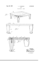
- FIG. 1 is a perspective view of the stool embodying my invention with portions broken away to show structural details.
- FIG. 2 is a front elevational view of the stool embodying the invention.
- FIG. 3 is an enlarged fragmentary view partially in section on a line corresponding to line 3-3 of FIG. 2.
- the body portion 1 is rectangular but it should be understood that it may be circular, oval, or any other shape. That is, that the parts and the assembling thereof permit the variation in shape.
- the body member 1 is of molded construction, preferably being of molded wood chips, such as conventional chipboard.
- the body member 1 is substantially uniform in thickness throughout, does not warp and is extremely diliicnlt to crack or fracture. Bores 2 are spaced inwardly from the corners of the body member 1, there being recesses 3 in the upper side of the body member surrounding these bores 2.
- Legs '8 are desirably formed of wood and have fiat upper ends 9 of substantial diameter disposed in supporting engagement with the underside of the body member 1.
- the leg attaching members 10 are of substantial length and project into the legs, tight threaded engagement being desirable, and is conventionally illustrated at 11.
- These leg attaching members 10 are disposed centrally to the legs and have threaded projecting portions 12 which have threaded engagement with the coupling members 4 which are, as stated, nonrotatably secured to the body member thus attaching the legs to the body member 1.
- the legs 7 thus may be quickly engaged with or disengaged [from the tubular coupling members fixedly mounted on the body member.
- the leg attaching members are hanger bolts.
- a relatively thin unitary top panel 14 is dimensioned to correspond to the body member, as is illustrated in the drawings, and completely covers the body member and is adhesively secured, as indicated at 15, to the body member.
- the top panel is relatively hard and tough and provides a durable covering for the body member 1.
- the top panel locks the coupling members 4 rigidly in the body member 1.
- the top panel is of a molded fiber material widely known as Masonite and has a textured under surface well adapted to a strong adhesive bond.
- a finish layer 16 is illustrated but is desirably of such character that it does not appear in the assembled structure and it is illustrated in the drawings merely to illustrate a complete embodiment of my invention.
- the opposed faces of the top panel and body member have such texture as to receive a substantial amount of the adhesive so that the top panel is secured to the body member without the necessity of using screws or similar attaching devices and a perfectly smooth outer surface on the top panel is provided which is desirable from the use and the appearance standpoints.
- the legs are desirably provided with bottom pieces 17 secured thereto by the nails 18 and serves the double purpose of substantially eliminating the sliding of the stool on a smooth surface and also in preventing noise when the stool is set on a hard surface while preventing man-ing of such surfaces.
- the embodiment of my invention illustrated may be economically produced both in material and the forming and assembling of the elements.
- the embodiment illustrated, in which the top portion is rectangular, is a desirable structure but it may be other shapes, for example, round and all of these varying shapes may be economically produced both from the angle of material and the assembling thereof.
- a stool comprising:
- a one-piece rigid body member of substantially uniform thickness having substantially flat parallel top and bottom surfaces, said body member being molded of particulate mate-rial so as to have high strength and toughness, said body member having a plurality of laterally spaced openings therethrough, said body member having enlarged annular recesses formed in the top surface thereof and surrounding the upper ends of said openings, said recesses extending only partway through said body member;
- leg coupling members snugly received within and extending through said Openings, said leg coupling members having enlarged annular flanges at their upper ends disposed in said recesses and a plurality of downwardly projeetin g lugs embedded in the bottom walls of the recesses and securing said leg coupling members against rotation with respect to said body member;
Landscapes
- Tables And Desks Characterized By Structural Shape (AREA)
Description
g- 29, 1957 J. J. HAMMOND 3,338,190
STOOL Filed March 5, 1966 INVENTOR U 7 WM? ATTO/QA/[V United States Patent This invention relates to stools. The main objects of this invention are:
First, to provide a stool which is well adapted for use by children and is capable of withstanding severe usage such as, for example, dropping or throwing.
Second, to provide a stool having these advantages which is economical to produce and one which is relatively light in weight in proportion to its load supporting capacity.
Third, to provide a stool in which the legs are effectively but detachably connected to the body so that the stool may be compactly arranged for shipment or storage and may be quickly and easily set up without the use of tools.
Fourth, to provide a structure having these advantages in which parts do not warp or become out of shape.
Fifth, to provide a structure having all of these advantages which may be economically produced.
Additional objects and advantages of the invention will be apparent to persons acquainted with devices of the type upon reading the following description and inspecting the accompanying drawings, in which:
FIG. 1 is a perspective view of the stool embodying my invention with portions broken away to show structural details.
FIG. 2 is a front elevational view of the stool embodying the invention.
FIG. 3 is an enlarged fragmentary view partially in section on a line corresponding to line 3-3 of FIG. 2.
In the embodiment of my invention illustrated, the body portion 1 is rectangular but it should be understood that it may be circular, oval, or any other shape. That is, that the parts and the assembling thereof permit the variation in shape. The body member 1 is of molded construction, preferably being of molded wood chips, such as conventional chipboard. The body member 1 is substantially uniform in thickness throughout, does not warp and is extremely diliicnlt to crack or fracture. Bores 2 are spaced inwardly from the corners of the body member 1, there being recesses 3 in the upper side of the body member surrounding these bores 2. Internally threaded leg coupling members 4 are fittingly disposed in these bores and they are provided with outwardly projecting flanges 5 on their uper ends which flanges are received within the enlarged recesses 3. These flanges 5 have downwardly projecting lugs 7 which are embedded in the body member thereby preventing rotative movement of the coupling members.
Legs '8 are desirably formed of wood and have fiat upper ends 9 of substantial diameter disposed in supporting engagement with the underside of the body member 1. The leg attaching members 10 are of substantial length and project into the legs, tight threaded engagement being desirable, and is conventionally illustrated at 11. These leg attaching members 10 are disposed centrally to the legs and have threaded projecting portions 12 which have threaded engagement with the coupling members 4 which are, as stated, nonrotatably secured to the body member thus attaching the legs to the body member 1. The legs 7 thus may be quickly engaged with or disengaged [from the tubular coupling members fixedly mounted on the body member. In the particular embodiment shown, the leg attaching members are hanger bolts.
A relatively thin unitary top panel 14 is dimensioned to correspond to the body member, as is illustrated in the drawings, and completely covers the body member and is adhesively secured, as indicated at 15, to the body member. The top panel is relatively hard and tough and provides a durable covering for the body member 1. In addition, the top panel locks the coupling members 4 rigidly in the body member 1. In this embodiment of my invention, the top panel is of a molded fiber material widely known as Masonite and has a textured under surface well adapted to a strong adhesive bond.
In the embodiment illustrated, a finish layer 16 is illustrated but is desirably of such character that it does not appear in the assembled structure and it is illustrated in the drawings merely to illustrate a complete embodiment of my invention. The opposed faces of the top panel and body member have such texture as to receive a substantial amount of the adhesive so that the top panel is secured to the body member without the necessity of using screws or similar attaching devices and a perfectly smooth outer surface on the top panel is provided which is desirable from the use and the appearance standpoints.
The legs are desirably provided with bottom pieces 17 secured thereto by the nails 18 and serves the double purpose of substantially eliminating the sliding of the stool on a smooth surface and also in preventing noise when the stool is set on a hard surface while preventing man-ing of such surfaces.
It is desired to point out that the embodiment of my invention illustrated may be economically produced both in material and the forming and assembling of the elements. The embodiment illustrated, in which the top portion is rectangular, is a desirable structure but it may be other shapes, for example, round and all of these varying shapes may be economically produced both from the angle of material and the assembling thereof.
When the legs are removed, there are no projections on the body portion so that the structure may be quite compactly arranged, the legs being placed sideways against the body member and the legs may be quickly attached to the body unit without the use of tools, which, as stated, is highly desirable when viewed from the several stated angles.
Although a particular preferred embodiment of the invention has been disclosed above for illustrative purposes, it will be understood that variations or modifications thereof which lie within the scope of the appended claim are fully contemplated.
Having thus described the invention, what is claimed as new and desired to secure by Letters Patent is:
A stool comprising:
a one-piece rigid body member of substantially uniform thickness having substantially flat parallel top and bottom surfaces, said body member being molded of particulate mate-rial so as to have high strength and toughness, said body member having a plurality of laterally spaced openings therethrough, said body member having enlarged annular recesses formed in the top surface thereof and surrounding the upper ends of said openings, said recesses extending only partway through said body member;
internally threaded, tubular, leg coupling members snugly received within and extending through said Openings, said leg coupling members having enlarged annular flanges at their upper ends disposed in said recesses and a plurality of downwardly projeetin g lugs embedded in the bottom walls of the recesses and securing said leg coupling members against rotation with respect to said body member;
a plurality of legs connected to said body member, the upper portion of said legs being of larger size than said openings and having integral shoulder means 7 supportedly engaging the bottom surface of said body member;
attaching means for said legs fixedly secured thereto and having externally threaded portions projecting 11pwardly (from the upper ends of said legs, said threaded [portio'ns extending into and being threadedly engaged with said coupling members for fixedly interconnecting said legs and said body member; and
a one-piece thin panel of form retaining material adhesively secured to the top surface of said body mem :ber, said panel and said body member being coextensive in shape and size such that said panel covers,
the upper ends of said openings and recesses.
1,094,900 4/1914 Holt 108-156 X 1,948,724 2/1934 Laun 108-156 X 2,602,012 7/1952 Doty 248188 2,730,419 1/1956 Watrous et al 108-456 3,159,423 12/1964 Gilbert 108156 X 3,176,353 4/1965 Pilliod et al 56-624 X FOREIGN PATENTS 648,192 12/ 1928 France. 848,265 9/ 1960 Great Britain.
20 JAMES T. MCCALL, Examiner.
Priority Applications (1)
| Application Number | Priority Date | Filing Date | Title |
|---|---|---|---|
| US531542A US3338190A (en) | 1966-03-03 | 1966-03-03 | Stool |
Applications Claiming Priority (1)
| Application Number | Priority Date | Filing Date | Title |
|---|---|---|---|
| US531542A US3338190A (en) | 1966-03-03 | 1966-03-03 | Stool |
Publications (1)
| Publication Number | Publication Date |
|---|---|
| US3338190A true US3338190A (en) | 1967-08-29 |
Family
ID=24118062
Family Applications (1)
| Application Number | Title | Priority Date | Filing Date |
|---|---|---|---|
| US531542A Expired - Lifetime US3338190A (en) | 1966-03-03 | 1966-03-03 | Stool |
Country Status (1)
| Country | Link |
|---|---|
| US (1) | US3338190A (en) |
Cited By (8)
| Publication number | Priority date | Publication date | Assignee | Title |
|---|---|---|---|---|
| US3730109A (en) * | 1971-01-04 | 1973-05-01 | Armstrong Cork Co | Knock-down table structure |
| US4042199A (en) * | 1975-12-19 | 1977-08-16 | Clifford Wilbur Winkler | Molded furniture leg |
| US4676551A (en) * | 1985-11-12 | 1987-06-30 | Mcdowell John R | Fancy stool |
| US4813742A (en) * | 1987-12-22 | 1989-03-21 | Cardinael Barry P | Orthopedic footstool |
| WO1999052401A1 (en) * | 1998-04-10 | 1999-10-21 | Harold Klein | Convertible furniture unit |
| US20050215104A1 (en) * | 2002-12-09 | 2005-09-29 | Lipniarski David J | Indented female blow-molded connector and male connector and method |
| US20060113831A1 (en) * | 2004-11-26 | 2006-06-01 | Vernard Cancer | Lovestep |
| USD845012S1 (en) * | 2018-01-09 | 2019-04-09 | Carolyn Thomas | Vehicle step stool |
Citations (8)
| Publication number | Priority date | Publication date | Assignee | Title |
|---|---|---|---|---|
| US1094900A (en) * | 1913-08-25 | 1914-04-28 | Newton & Hoit Company | Table. |
| FR648192A (en) * | 1927-06-13 | 1928-12-06 | Force Et Lumiere Electr | Automatic locking and engagement device |
| US1948724A (en) * | 1932-06-06 | 1934-02-27 | Kiel Furniture Co | Furniture construction |
| US2602012A (en) * | 1949-11-03 | 1952-07-01 | George E Doty | Rotatable leg construction for reversible table tops |
| US2730419A (en) * | 1951-09-18 | 1956-01-10 | Gilbert A Watrous | Furniture support |
| GB848265A (en) * | 1958-03-11 | 1960-09-14 | James Johnson Handicrafts Ltd | Improvements in and relating to chair and like legs |
| US3159423A (en) * | 1964-12-01 | gilbert | ||
| US3176353A (en) * | 1963-05-13 | 1965-04-06 | Pilliod Cabinet Company | Table top construction |
-
1966
- 1966-03-03 US US531542A patent/US3338190A/en not_active Expired - Lifetime
Patent Citations (8)
| Publication number | Priority date | Publication date | Assignee | Title |
|---|---|---|---|---|
| US3159423A (en) * | 1964-12-01 | gilbert | ||
| US1094900A (en) * | 1913-08-25 | 1914-04-28 | Newton & Hoit Company | Table. |
| FR648192A (en) * | 1927-06-13 | 1928-12-06 | Force Et Lumiere Electr | Automatic locking and engagement device |
| US1948724A (en) * | 1932-06-06 | 1934-02-27 | Kiel Furniture Co | Furniture construction |
| US2602012A (en) * | 1949-11-03 | 1952-07-01 | George E Doty | Rotatable leg construction for reversible table tops |
| US2730419A (en) * | 1951-09-18 | 1956-01-10 | Gilbert A Watrous | Furniture support |
| GB848265A (en) * | 1958-03-11 | 1960-09-14 | James Johnson Handicrafts Ltd | Improvements in and relating to chair and like legs |
| US3176353A (en) * | 1963-05-13 | 1965-04-06 | Pilliod Cabinet Company | Table top construction |
Cited By (9)
| Publication number | Priority date | Publication date | Assignee | Title |
|---|---|---|---|---|
| US3730109A (en) * | 1971-01-04 | 1973-05-01 | Armstrong Cork Co | Knock-down table structure |
| US4042199A (en) * | 1975-12-19 | 1977-08-16 | Clifford Wilbur Winkler | Molded furniture leg |
| US4676551A (en) * | 1985-11-12 | 1987-06-30 | Mcdowell John R | Fancy stool |
| US4813742A (en) * | 1987-12-22 | 1989-03-21 | Cardinael Barry P | Orthopedic footstool |
| WO1999052401A1 (en) * | 1998-04-10 | 1999-10-21 | Harold Klein | Convertible furniture unit |
| US6296314B1 (en) * | 1998-04-10 | 2001-10-02 | Harold Klein | Convertible furniture unit |
| US20050215104A1 (en) * | 2002-12-09 | 2005-09-29 | Lipniarski David J | Indented female blow-molded connector and male connector and method |
| US20060113831A1 (en) * | 2004-11-26 | 2006-06-01 | Vernard Cancer | Lovestep |
| USD845012S1 (en) * | 2018-01-09 | 2019-04-09 | Carolyn Thomas | Vehicle step stool |
Similar Documents
| Publication | Publication Date | Title |
|---|---|---|
| US2993733A (en) | Molded chair construction | |
| US4235473A (en) | Furniture construction | |
| US5163373A (en) | Furniture with improved leg construction | |
| US3338190A (en) | Stool | |
| CA1075586A (en) | Chair and base frame therefor | |
| US2456929A (en) | Tray structure | |
| US1346955A (en) | Furniture | |
| US3307505A (en) | Furniture | |
| US3497262A (en) | Stackable,disassemblable chair | |
| US2580707A (en) | Chair of knockdown type | |
| US3323833A (en) | Readily expandable pedestal construction for one or more seating units | |
| US6725523B2 (en) | Knockdown chair | |
| US2499773A (en) | Article of furniture | |
| US3405915A (en) | Handrails | |
| US2166941A (en) | Knock-down furniture frame | |
| US2343494A (en) | Back assembly for composite metal and wood chairs | |
| US1311671A (en) | Planoqraph co | |
| US208768A (en) | Improvement in chair-braces | |
| CN208259364U (en) | A kind of evil spirit piece combination sideboard | |
| GB2247166A (en) | Furniture kit | |
| JPS60174109A (en) | Replaceable member used in assembling furniture | |
| US456752A (en) | Knockdown table | |
| US199824A (en) | Improvement in chair-bottoms | |
| CN208783959U (en) | With scratch resistant multifunctional dining table | |
| US168828A (en) | Improvement in chairs |