US3337088A - Mechanism for operating corded stack vending machines - Google Patents
Mechanism for operating corded stack vending machines Download PDFInfo
- Publication number
- US3337088A US3337088A US434512A US43451265A US3337088A US 3337088 A US3337088 A US 3337088A US 434512 A US434512 A US 434512A US 43451265 A US43451265 A US 43451265A US 3337088 A US3337088 A US 3337088A
- Authority
- US
- United States
- Prior art keywords
- coupling
- coupling member
- movement
- plate
- arm
- Prior art date
- Legal status (The legal status is an assumption and is not a legal conclusion. Google has not performed a legal analysis and makes no representation as to the accuracy of the status listed.)
- Expired - Lifetime
Links
Images

Classifications
-
- A—HUMAN NECESSITIES
- A47—FURNITURE; DOMESTIC ARTICLES OR APPLIANCES; COFFEE MILLS; SPICE MILLS; SUCTION CLEANERS IN GENERAL
- A47F—SPECIAL FURNITURE, FITTINGS, OR ACCESSORIES FOR SHOPS, STOREHOUSES, BARS, RESTAURANTS OR THE LIKE; PAYING COUNTERS
- A47F1/00—Racks for dispensing merchandise; Containers for dispensing merchandise
- A47F1/04—Racks or containers with arrangements for dispensing articles, e.g. by means of gravity or springs
- A47F1/08—Racks or containers with arrangements for dispensing articles, e.g. by means of gravity or springs dispensing from bottom
- A47F1/10—Racks or containers with arrangements for dispensing articles, e.g. by means of gravity or springs dispensing from bottom having mechanical dispensing means, e.g. with buttons or handles
-
- G—PHYSICS
- G07—CHECKING-DEVICES
- G07F—COIN-FREED OR LIKE APPARATUS
- G07F11/00—Coin-freed apparatus for dispensing, or the like, discrete articles
- G07F11/02—Coin-freed apparatus for dispensing, or the like, discrete articles from non-movable magazines
- G07F11/04—Coin-freed apparatus for dispensing, or the like, discrete articles from non-movable magazines in which magazines the articles are stored one vertically above the other
- G07F11/08—Coin-freed apparatus for dispensing, or the like, discrete articles from non-movable magazines in which magazines the articles are stored one vertically above the other arranged in two columns in staggered relationship
-
- Y—GENERAL TAGGING OF NEW TECHNOLOGICAL DEVELOPMENTS; GENERAL TAGGING OF CROSS-SECTIONAL TECHNOLOGIES SPANNING OVER SEVERAL SECTIONS OF THE IPC; TECHNICAL SUBJECTS COVERED BY FORMER USPC CROSS-REFERENCE ART COLLECTIONS [XRACs] AND DIGESTS
- Y10—TECHNICAL SUBJECTS COVERED BY FORMER USPC
- Y10T—TECHNICAL SUBJECTS COVERED BY FORMER US CLASSIFICATION
- Y10T74/00—Machine element or mechanism
- Y10T74/18—Mechanical movements
- Y10T74/18992—Reciprocating to reciprocating
-
- Y—GENERAL TAGGING OF NEW TECHNOLOGICAL DEVELOPMENTS; GENERAL TAGGING OF CROSS-SECTIONAL TECHNOLOGIES SPANNING OVER SEVERAL SECTIONS OF THE IPC; TECHNICAL SUBJECTS COVERED BY FORMER USPC CROSS-REFERENCE ART COLLECTIONS [XRACs] AND DIGESTS
- Y10—TECHNICAL SUBJECTS COVERED BY FORMER USPC
- Y10T—TECHNICAL SUBJECTS COVERED BY FORMER US CLASSIFICATION
- Y10T74/00—Machine element or mechanism
- Y10T74/20—Control lever and linkage systems
- Y10T74/20012—Multiple controlled elements
Definitions
- This invention relates to dispensing or vending apparatus, more particularly to a mechanism for alternately coupling one and then the other of two dispensing mechanisms to a common operating mechanism therefor. It relates more particularly to such a coupling mechanism which can be rendered effective or ineffective and which, when ineffective, will remain in the position determining the next dispensing mechanism of the pair to be operated, regardless of the number of intervening operations of the common operating mechanism for operating other dispensing mechanisms.
- the object of the invention is to provide an improved coupling mechanism of this type, more particularly one that is simpler and less expensive.
- Another object is to provide a mechanism in which there are a minimum number and a minimum weight of parts of the coupling mechanism that are carried by the common operating mechanism during a dispensing operation.
- Another object is to, provide a mechanism of this character in which the selection solenoids for controlling the coupling mechanisms are provided and are stationary, so as to avoid the bending of wires that is encountered when such solenoids are mounted on a movable structure.
- each dispensing mechanism is provided with a member, such as a vertically slidable plate, which is actuated to dispense an article.
- the common operating mechanism includes a drive member that moves upwardly and then downwardly during each dispensing operation, to move the selected plate upwardly and then downwardly.
- Each coupling member has one arm extending generally in the direction of movement of the drive member, upwardly in this case, and this arm is movable into and out of coupling relation to the common drive member upon pivotal movement of the coupling member in one direction.
- the two coupling members also have projections or transverse arms extending toward and into abutting relation to each other and they are formed so that the projection of the coupling member which is in or nearest to coupling position limits the movement of the other coupling member to keep it out of coupling position.
- each coupling mechanism In order to provide selection of the coupling mechanism which is to connect a dispensing mechanism during the next dispensing operation, there is provided for each coupling mechanism a movable stop which is adapted to engage the projection of either coupling member to prevent the same from moving into coupling relation.
- the associate-d stop When a particular coupling mechanism is to be operated, the associate-d stop is moved out of the way by a solenoid to permit the coupling member which is in or nearest 7 the coupling position to be connected to the common drive member to be operated thereby.
- Another feature resides in the provision of cam surfaces on the common drive member which, in the standby or rest position of the drive member, retain all coupling members out of coupling position and thereby maintain all projections out of engagement with the stop members. This provides free movement of the stop members without frictional engagement with the projections of the coupling members, and it also permits return movement of the stop member to effective position in the event that a particular solenoid is quickly deenergized.
- FIG. 1 is a front elevation of a portion of a dispensing or vending machine including the operating plates for two dispensing mechanisms, a common drive member and a coupling mechanism for alternately coupling one and then the other operating plate to the common drive member; 7
- FIG. 2 is a similar view, but showing two pairs of operating plates and two coupling mechanisms therefor, and also showing the drive member in partially raised position;
- FIG. 3- is a similar elevational view showing the drive member in a further advanced position
- FIG. 4 is a fragmentary elevational view showing the coupling mechanism is reversed standby or rest position
- FIG. 5 shows one form of bottle releasing mechanism for a corded stack
- FIG. 6 is a similar view, but showing one of the re leasing mechanisms in releasing position and also show I ing the cam plates for operating the same;
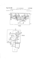
- FIG. 7 is a vertical section taken on the line VII-VII of FIG. 1;
- FIG. 8 is a horizontal section taken on the line VIII- VIII of FIG. 1;
- FIG. 9 is a diagram of a portion of a circuit network that may be used with the apparatus.
- FIG. 10 is an elevational view showing a modification.
- FIGS. 1 and 2 vertically slidable plates 11 and 12, which operate two adjacent article dispensing or releasing mechanisms of any suitable form, such as, for example, the
- FIGS. 5 and 6 There may be any number of pairs of similar plates for bottle releasing mechanisms for an equal number of corded stacks; for example, in FIG. 2 there is shown a second pair of plates 13 and 14, similar to plates 11 and 12 re-' spectively and FIG. 3 refers specifically to the second pair of plates 13, 14.
- the mentioned plates extend, and are vertically movable, through slots 15 in the upperand lower flanges 16 of a stationary channel member 17.
- the mentioned plates are sometimes referred to as operated members since they are operated by the common operating mechanism through the coupling mechanism of this invention.
- a common operating mechanism for operating all of the vertically slidable plates such as plates 11,- 12, 13 and 14 is provided and may be of any suitable form, such as that shown in FIGS. 1 and 7 and which will be described later. It includes a common drive member 18, which is in the form of an angle member extending horizontally along said plates. Both the plate to be operated and the common drive member move or reciprocate upwardly and downwardly in one dispensing operation, remaining at the lowermost end of their travel in the rest or standby condition of the apparatus, as shown in FIG. 1.
- the coupling mechanism also termed an alternator mechanism, which forms the subject matter of the present invention.
- This alternator mechanism may comprise two pairs of coupling members or pick-up plates 19, 19a and 20, 20a pivotally mounted on the respectively operating plates 11, 12, 13, and 14 by pivots 21, 21a and 22, 22a on pivot axes that are disposed in spaced parallel relation and extend'horizontally or transversely of the direction of movement of the plates.
- Each of the coupling members 19, 19a and 20, 20a comprises a first arm such as arms 23, 23a for members 19, 20 which extends in the direction of movement, in this case, vertically or upwardly.
- the upper end of the arms 23, 23a and the common drive member 18 have cooperating interlocking portions which are adapted to effect a driving connection therebetween upon pivotal movement of the coupling member into coupling position.
- Such cooperating parts comprise studs or pins 24, 24a on the upper end of the arms 23,- 23a respectively and a downward projection 25 of the common drive member 18 which is formed with a notch 26, 26a for each pin 24, 24a to receive the same. Pivotal or tilting movement of the coupling member in which the pin moves into the notch 26 or 26a will be referred to herein as inward movement, and movement in which the pin moves out of the notch will be referred to herein as outward movement.
- Each coupling member is biased in the direction of inward movement by any suitable biasing means, such as a torsion spring 27, 27a shown in FIG. 8.
- a coil tension spring (not shown) may be connected between the studs 24, 24a to bias members 19, 20 towards each other.
- the coupling members 19 and 20 further comprise second or transverse arms 190 and 200 which extend transversely of the first arms and toward and in overlapping and abutting relation to each other.
- the transverse arms 190 and 200 are also referred to herein as projections.
- the transverse arms 190, 200 are disposed one above the other, the one in the lower position limiting the downward movement of the other to prevent the other coupling member from reaching coupling position.
- a movable stop 28 which is adapted to limit the downward movement of the lower transverse arm 190 or 200 by abutment with a pin 29, 2901 which is provided at the outer end of each transverse arm.
- the pin 29a of the right-hand coupling member 20 is held by the stop 28 in a position in which its pin 24a is held out of the associated notch 26a of the projection 25.
- the notch 26a of the projection 25 of the drive member 18 does not engage the pin 24a and neither of the plates 11 and 12 is raised since likewise pin 24 is not engaged with notch 26.
- the stop 28 is provided by an upwardly-extending projection of a plate 30 which is horizontally slidable on the "lower flange 16 of the channel member 17.
- the stop 28 is biased to the left to its effective position as shown by FIG. 1 by a tension spring 31 connected at one end to a lower projection 32 of the plate 30 and at its other end to a bracket 33 fixed to the flange 16.
- the stop is adapted to be actuated to the right to its ineffective position as shown for operating members 13 and 14 of FIG. 2 in which it is out of the way of either of the pins 29b or 29c, by a solenoid 34 whose armature 35 is also connected to the lower projection 32.
- the plate 30 may be provided with a struck-out projection 30a to operate a switch 3%, as shown in FIG.'8, should such switch be desired in the electrical control, as for closing a holding circuit to the solenoid 34.
- This means comprises two pins 36, 36a and 37, 37a fixed to the respective plate 30 and extending through slots 38a, 38b, 38c and 38d in the vertically slidable plates 11, 12, 13 and 14 respectively.
- each slot such as the surface 390 of the slot 38d moves into engagement with a respective pin such as the pin 37a if such pin has not returned to its rest position, and forcibly moves it to the left in line with the lower portion of each of the slots 38a, 38b, 38c, or 38d.
- Suitable means such as a strap 40, fastened to the flange 16 (FIGS. 7 and 8), is provided to prevent the pin from being tilted upwardly by the thrust of each inclined cam surface such as the surface 39.
- each projection 25 of the drive member 18 is formed with an inclined cam surface 41, 41a, 41b and 41c and a vertical cam surface such as the surface 42, 42a, 42b and 42c for each respective pin 24, 24a, 24b, or 240 to engage the pin and effect outward movement of the coupling member sufiicient to maintain its associated pin 29, 29a, 2% or 290 spaced above the associated stop 28.
- a second important purpose of this spacing is to permit the associated stop 28 to be returned to its effective position in the event that the solenoid 34 is quickly de-energized.
- a small projection 43, 43a, 43b, 43c is provided between the respective surfaces 41, 41a, 41b, 41c and 42, 42a, 42b, 42c for the purpose of providing positive movement of the coupling member to break loose any ice formation that may have developed, since this type of mechanism frequently operates in a region that is a temperature below the freezing point of water.
- FIGS. 5 and 6 there is shown one form of bottle releasing mechanism, which is described and claimed in application Ser. No. 173,222, now Patent No. 3,209,942, of Francis A. Gasparini and James E. Howard, Jr., that may be used in connection with the present invention. It is shown in connection with a magazine or compartment of the corded stack type, comprising side walls 44 and 45 which are spaced to accommodate two columns of bottles in vertically staggered, horizontally overlapping relation as shown.
- the bottle releasing mechanism each comprises two rods 46 and 47 disposed under the respective columns and extending lengthwise thereof.
- the rod 46 is fixed to the lower ends of lever 48 pivoted on a pivot axis 49, the lever 48 at one end having a cam follower 50, in the form of a roller, extending through a cam slot 51 in the vertically slidable plate 12 of FIG. 1.
- the rod 47 is fixed on the lower ends of lever 52 pivoted on a pivot axis 53, the other end of the lever 52 having an arm extending upwardly from the pivot and carrying a cam follower or roller 54 extending through a cam slot 55 in the vertically slidable plate 11 (FIG. 1).
- Each of the cam slots 51 and 55 in the operating plates 11, 12 includes an upper portion 56, 56a which positions the associated rod 46 or 47 in the bottle supporting position shown in FIG. 5, a lower portion 57, 57a which positions the associated rod in the releasing position, such as the position of the rod 46 shown in FIG. 6, and an intermediate inclined portion 58, 58a for moving the rod from supporting position to releasing position upon upward movement of the plate and for returning the rod to supporting position upon return downward movement of the plate.
- the slots 51 and 55 are omitted in some views to show more clearly the present invention.
- the common operating mechanism above referred to for operating the several bottle mechanisms comprises, in addition to the drive member 18, vertical plates 59 that extend, and are vertically movable, through slots 60 in the upper and lower horizontal flanges 16 of the stationary channel member 17.
- the drive member 18 is carried by the plates 59, in any suitable manner; for example, the drive member may have end portions 61 extending through slots 62 in the plates 59 as shown in FIG. 1.
- the plates 59 may be raised and lowered by a motor and speed reducer unit 63, shown in FIG. 7, through a mechanism which includes a horizontal oscillating rock shaft 64 journalled in the brackets 33 attached to the channel flange 16 and having fixed thereon levers 65 provided with pins 66 at their outer ends that extend through horizontal slots 67 in the lower ends of the plates 59.
- a lever 68 is also fixed at one end to the shaft 64 and at its outer end is pivoted to a connecting rod 69, the other end of which is pivoted at 70 to a cam plate 71 of the motor and speed reducer unit 63, which plate here serves as a crank for actuating the connecting rod 69.
- the plate 11 is notched, as shown in FIGS. 1 and 2, to accommodate lever 68.
- the cam plate 71 makes one revolution for each dispensing or vending operation of the machine, starting from the lowermost position of the pin 70 shown in FIG. 7.
- the pin 70 moves upwardly and, through the connecting rod 69, the lever 68, the shaft 64, the levers 65 and the pins 66, moves the end plates 59 and the drive member 18 upwardly.
- the pin 70 moves downwardly and, through the same parts just mentioned, moves the drive member 18 downwardly to its lowermost or standby position.
- the cam plate 71 actuates a switch 72, which controls, among other things, the energization of the solenoids 34 in FIG. 10.
- the common drive member 18 is at the lower end of its travel as shown in FIGS. 1 and 7. All of the stops 28 are in effective or blocking position to prevent downward movement of the lower one of the transverse arms such as arms 19a, 20a etc.
- one of the solenoids 34 is energized to move its associated stop 28 out of alignment with the associated pin of the lower transverse arm such as pin 290 (FIG. 2).
- the remaining stops 28 are retained in their effective or block ing position.
- Operation of the motor and speed reducer unit 63 is initiated to effect one complete revolution of the cam plate 71.
- the solenoid 34 is de-energized to permit the stop 28 to return to effective position such as the position shown for stop 28 associated with plates 11, 12. This is effected by the electrical control in any suitable manner; for example, by the cam plate 71 opening the switch 72.
- the stop 28 fails to return upon de-energiz-ation of the solenoid, it is positively returned to effective position by engagement of the cam surface 390 of the raised plate .14 with the pin 37a, these surfaces being disposed to effect such return before the non-operated coupling member is released by the operated coupling member.
- the transverse arm 200a raises the transverse arm 190a to move the member 19a outwardly or counterclockwise as shown in FIG. 3.
- the transverse arm 200a moves out of engagement with the transverse arm 190a, whereupon the transverse arm 190a is moved inwardly or clockwise until its pin 29b engages the stop 28 as shown in dot-and-dash lines in FIG. 3.
- the stop 28 it has been necessary that the stop 28 be returned as previously described to its effective position by this time in order that it may control the coupling member 19a in the next dispensing operation.
- the drive member 18 and the plate 14 continue their upward movement and then return downwardly to standby position.
- the cam slot 51 therein moves the releasing rod 46 to releasing position, as shown in FIG. 6, and then back to supporting position, as shown in FIG. 5.
- the left-hand inclined cam surface 41b engages the left-hand pin 24b to move the coupling member 19a outwardly and spaced its pin 29b from the stop 28.
- the apparatus described above may be controlled by any suitable electrical control, as is already well-known in the art; for example, the control disclosed and claimed in application, Ser. No. 342,404, now Patent No. 3,209,- 946, of J. Kalista, is well suited for this apparatus.
- FIG. 9 shows a transfer switch circuit arrangement of the type disclosed and claimed in application, Ser. No. 367,480, now Patent No. 3,240,386, of G. S. McCloy.
- the control includes a transfer switch 78 actuated to one position by the plate 12 upon upward movement and to the opposite position by the plate 13 upon upward movement thereof, and a second transfer switch 79 similarly controlled by the plates 14- and 76. Current is supplied through a conductor 80, the switch 72, a conductor 81, a selector switch 82, and a conductor 83.
- plate 76 Upon operation of plate 76, its alternator mechanism is set for the next operation of plate 77 and the transfer switch 79 is moved counterclockwise to extend the circuit from conductor 83 through switch 79, conductor 84 and the transfer switch 78 to the conductor 74. Accordingly, plate 13 is the next to be operated. Its alternator mechanism is set for next operation of plate 14 and the transfer switch 78 is moved counterclockwise so that in the next operation a circuit will be extended from conductor 83 through transfer switch 79, conductor 84 and transfer switch 78 to conductor 73 for the next operation of plate 11. Upon operation of plate 11, its alternator mechanism is set for next operation of plate 12, and neither transfer switch is actuated.
- FIG. 10 there is shown a coupling mechanism in which a single coupling member 90 is employed to control a plate 14a independently of any other plate.
- the plate 14a may control the dispensing mechanism for a stack holding a single column of bottles.
- the plate 14a may, for example, operate a bottle releasing mechanism of the type shown and claimed in Patent 3,118,567 of M. W. Newberry.
- the common drive member 1843 has a projection 2511, which is generally similar to the projection 25 except that it is narrower and of greater vertical extent to provide for some upward movement of the drive member 18;: before the pin 240 enters the notch 260 to connect the coupling member to the drive member.
- the coupling member 90 is controlled in the same manner as in the first embodiment, namely, by a stop 28 movable into or out of position locking the pin 99 of the coupling member 90.
- FIG. 10 also shows a lock member 85 having a projection 86 disposed immediately above the pin 240 so as to prevent manual raising of the plate 14a.
- the pin 240 moves to the left, so that the projection 86 is entirely out of the way.
- the lock member 85 is pivoted to stationary structure at 87 and is biased clockwise against a stationary stop 88, and it has an inclined upper surface 89 on the upper side of the projection 86.
- the lock member 85 upon downward movement of the coupling member 90 when its pin 99 abuts the stop 28, the lock member 85 will yield and rotate counterclockwise when the pin 240 strikes the inclined surface 89.
- an alternator mechanism for alternately coupling one and then the other of said operated members to said common drive member comprising two coupling members pivoted to said operated members respectively on parallel axes extending transversely of the direction of movement and spaced from each other transversely of said direction of movement,
- each coupling member having one arm extending in the direction of movement and another arm extending transversely thereof
- each said one arm and the common drive member having cooperating parts brought into interlocking relation to couple the operated member to the common drive member upon pivotal movement of the coupling member in one direction
- each coupling member when in its coupling position being disposed in the path of movement of the transverse arm of the other coupling member and limiting movement of the latter in said one direction to prevent its movement into coupling position, but being moved out of the path of said transverse arm of the other coupling member upon movement effected by the common drive member, whereupon said other coupling member moves to coupling position where it may be coupled to the common drive member in the next operation thereof.
- first and second coupling members pivotally mounted on said first and second movable members and having interengaging arms extending toward each other in overlapping abutting relation
- each coupling member and the drive means having cooperating parts which are brought into interlocking relation upon suflicient downward movement of the interengaging arm
- Dispensing apparatus comprising two dispensing mechanisms disposed side-by-side and each including a vertically slidable plate for operating the mechanism
- a common operating mechanism including a vertically reciprocable drive member movable upwardly and then downwardly in a dispensing operation
- coupling members pivoted to said plates on spaced, parallel, horizontal axes and including vertically-extending arms and also including transverse arms extending toward and overlapping each other,
- each vertically-extending arm and the common drive member having cooperating portions which are brought into interlocking engagement upon suflicient tilting movement of the coupling member in the direction of downward movement of the transverse arm,
- each coupling member in said direction of interlocking engagement, the lower of said overlapping transverse arms limiting the downward movement of the other transverse arm 5 to prevent engagement of the vertically-extending arm of the latter with the common drive member.
- the coupling member whose transverse arm is at the moment below the other being adapted, when required downward movement of such transverse arm is not prevented, to have its vertical arm interlocked with the common drive member and to be raised thereby during a dispensing operation sufliciently for its transverse arm to disengage the other transverse arm, whereupon the latter is moved downwardly by its biasing means and is under the firstmentioned transverse arm when the latter returns downwardly toward the end of the dispensing opertion, whereby the positions of the transverse arms are re- 0 versed so that in the next operation of the common drive member in which one of these two dispensing mechanisms is to be operated, the other coupling member engages the common drive member and is raised thereby to actuate its associated dispensing mechanism.
- Dispensing apparatus as set forth in claim 5 and further including means for selectively preventing or permitting sufiicient downward movement of the lower horizontal 3O arm to permit the associated vertical arm to move into interlocking or coupling engagement with the common drive member.
- Dispensing apparatus as set forth in claim 5 and further including an abutment or stop member adapted to be positioned selectively in a first position in which it abuts and limits downward movement of the lower transverse arm sufiiciently to prevent its associated vertical arm moving into interlocking relation to the common drive member, and to a second position in which it does not prevent such movement of the lower transverse arm, and means for selectively moving said stop member to either said first position or said second position.
Description
Aug? 2, 1967 M. w. NEWBERRY 3,337,988
MECHANISM FOR OPERATING CORDED STACK VENDING MACHINES Filed Feb. 23, 1965 6 Sheets-Sheet 1 iNVENTOR Meigs W Newberry 7 ATTORNEY Aug. 22, 1967 M. w. NEWBERRY MECHANISM FOR OPERATING CORDED STACK VENDING MACHINES 6 Sheets-Sheet 2 Filed Feb. 25, 1965 FIG.2.
Aug. 22, 1967 M. w NEWBERR'Y' MECHANISM FOR OPERATING CORDED STACK VE Filed Feb. 23, 1965 NDING MACHINES 6 Sheets-Sheet 3 Aug. 22, 1967 M. w. NEWBERRY 1 3,337,@3$
MECHANISM FOR OPERATING CORDED STACK VENDING MACHINES Filed Feb. 23, 1965 6 SheetS-Sheet 4 84 72 7a 79 73 74 75 -so all llll
M. W NEWBERRY Aug. 22, we?
I MECHANISM FOR OPERATING CORDED STACK VENDING MACHINES Filed Feb. 23, 1965 6 Sheets-Sheet 51 Aug. 22, 1967 MECHANISM FOR OPERATING CORDED STACK VENDING MACHINES M. w. NEWBERRY 3,337,0S8
Filed Feb. 23, 1965 an 4a F IG.8.
I80 89 as FIGJO 240 r 90 I 42 99 I J I 28 -2eo I \f\ I Y// I Y fi I 'M -=z I a l I 0| 6 Sheets-Sheet (7 United States Patent Ofifice 3,337,088 Patented Aug. 22, 1967 ABSTRACT OF THE DISCLOSURE A vending machine of the corded stack column, multiple column type having a release rod for each stack in each column with a single actuator together with means to alternately connect one each of the two column release rods to the actuator whereby alternate rods are actuated to release for successive release operations.
This invention relates to dispensing or vending apparatus, more particularly to a mechanism for alternately coupling one and then the other of two dispensing mechanisms to a common operating mechanism therefor. It relates more particularly to such a coupling mechanism which can be rendered effective or ineffective and which, when ineffective, will remain in the position determining the next dispensing mechanism of the pair to be operated, regardless of the number of intervening operations of the common operating mechanism for operating other dispensing mechanisms.
The object of the invention is to provide an improved coupling mechanism of this type, more particularly one that is simpler and less expensive.
Another object is to provide a mechanism in which there are a minimum number and a minimum weight of parts of the coupling mechanism that are carried by the common operating mechanism during a dispensing operation.
Another object is to, provide a mechanism of this character in which the selection solenoids for controlling the coupling mechanisms are provided and are stationary, so as to avoid the bending of wires that is encountered when such solenoids are mounted on a movable structure.
In the illustrated embodiment of the present invention, each dispensing mechanism is provided with a member, such as a vertically slidable plate, which is actuated to dispense an article. The common operating mechanism includes a drive member that moves upwardly and then downwardly during each dispensing operation, to move the selected plate upwardly and then downwardly. In accordance with the present invention, there are also provided coupling members pivoted to the respective plates. Each coupling member has one arm extending generally in the direction of movement of the drive member, upwardly in this case, and this arm is movable into and out of coupling relation to the common drive member upon pivotal movement of the coupling member in one direction. The two coupling members also have projections or transverse arms extending toward and into abutting relation to each other and they are formed so that the projection of the coupling member which is in or nearest to coupling position limits the movement of the other coupling member to keep it out of coupling position.
During a dispensing operation, that coupling member which has been permitted to move into coupling position is actuated by the drive member and during the course of its movement its projection moves out of engagement with the other coupling member, so that said other coupling member is moved by its biasing means to coupling position. The first coupling member, upon its return movement, abuts the projection of said other coupling member 1 and is thereby moved out of coupling relation to the drive member. Accordingly, upon the next operation of the machine in which this particular coupling mechanism is allowed to operate the said other coupling member will be in coupling position and will be connected to the drive. member to actuate its dispensing mechanism. Thus, the positions of the coupling members are reversed so that one and then the other of the two dispensing mechanisms will be operated alternately in those operations of the machine in which one of the two dispensing mechanisms is to be operated.
In order to provide selection of the coupling mechanism which is to connect a dispensing mechanism during the next dispensing operation, there is provided for each coupling mechanism a movable stop which is adapted to engage the projection of either coupling member to prevent the same from moving into coupling relation. When a particular coupling mechanism is to be operated, the associate-d stop is moved out of the way by a solenoid to permit the coupling member which is in or nearest 7 the coupling position to be connected to the common drive member to be operated thereby.
Another feature resides in the provision of cam surfaces on the common drive member which, in the standby or rest position of the drive member, retain all coupling members out of coupling position and thereby maintain all projections out of engagement with the stop members. This provides free movement of the stop members without frictional engagement with the projections of the coupling members, and it also permits return movement of the stop member to effective position in the event that a particular solenoid is quickly deenergized.
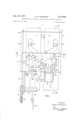
FIG. 1 is a front elevation of a portion of a dispensing or vending machine including the operating plates for two dispensing mechanisms, a common drive member and a coupling mechanism for alternately coupling one and then the other operating plate to the common drive member; 7
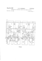
FIG. 2 is a similar view, but showing two pairs of operating plates and two coupling mechanisms therefor, and also showing the drive member in partially raised position;
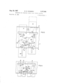
FIG. 3- is a similar elevational view showing the drive member in a further advanced position;
FIG. 4 is a fragmentary elevational view showing the coupling mechanism is reversed standby or rest position;
FIG. 5 shows one form of bottle releasing mechanism for a corded stack;
FIG. 6 is a similar view, but showing one of the re leasing mechanisms in releasing position and also show I ing the cam plates for operating the same;
. FIG. 7 is a vertical section taken on the line VII-VII of FIG. 1;
FIG. 8 is a horizontal section taken on the line VIII- VIII of FIG. 1;
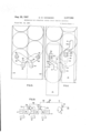
FIG. 9 is a diagram of a portion of a circuit network that may be used with the apparatus, and
FIG. 10 is an elevational view showing a modification. Referring to the drawings in detail, there are shown in FIGS. 1 and 2 vertically slidable plates 11 and 12, which operate two adjacent article dispensing or releasing mechanisms of any suitable form, such as, for example, the
two bottle releasing mechanisms for a corded stack shown in FIGS. 5 and 6, which will be described later. There may be any number of pairs of similar plates for bottle releasing mechanisms for an equal number of corded stacks; for example, in FIG. 2 there is shown a second pair of plates 13 and 14, similar to plates 11 and 12 re-' spectively and FIG. 3 refers specifically to the second pair of plates 13, 14. The mentioned plates extend, and are vertically movable, through slots 15 in the upperand lower flanges 16 of a stationary channel member 17.
The mentioned plates are sometimes referred to as operated members since they are operated by the common operating mechanism through the coupling mechanism of this invention.
A common operating mechanism for operating all of the vertically slidable plates such as plates 11,- 12, 13 and 14 is provided and may be of any suitable form, such as that shown in FIGS. 1 and 7 and which will be described later. It includes a common drive member 18, which is in the form of an angle member extending horizontally along said plates. Both the plate to be operated and the common drive member move or reciprocate upwardly and downwardly in one dispensing operation, remaining at the lowermost end of their travel in the rest or standby condition of the apparatus, as shown in FIG. 1.
To alternately connect one and then the other of the two plates of a pair to the common drive member 18, there is provided the coupling mechanism, also termed an alternator mechanism, which forms the subject matter of the present invention. This alternator mechanism may comprise two pairs of coupling members or pick-up plates 19, 19a and 20, 20a pivotally mounted on the respectively operating plates 11, 12, 13, and 14 by pivots 21, 21a and 22, 22a on pivot axes that are disposed in spaced parallel relation and extend'horizontally or transversely of the direction of movement of the plates. Each of the coupling members 19, 19a and 20, 20a comprises a first arm such as arms 23, 23a for members 19, 20 which extends in the direction of movement, in this case, vertically or upwardly. The upper end of the arms 23, 23a and the common drive member 18 have cooperating interlocking portions which are adapted to effect a driving connection therebetween upon pivotal movement of the coupling member into coupling position. Such cooperating parts comprise studs or pins 24, 24a on the upper end of the arms 23,- 23a respectively and a downward projection 25 of the common drive member 18 which is formed with a notch 26, 26a for each pin 24, 24a to receive the same. Pivotal or tilting movement of the coupling member in which the pin moves into the notch 26 or 26a will be referred to herein as inward movement, and movement in which the pin moves out of the notch will be referred to herein as outward movement. Each coupling member is biased in the direction of inward movement by any suitable biasing means, such as a torsion spring 27, 27a shown in FIG. 8. Alternatively, a coil tension spring (not shown) may be connected between the studs 24, 24a to bias members 19, 20 towards each other.
The coupling members 19 and 20 further comprise second or transverse arms 190 and 200 which extend transversely of the first arms and toward and in overlapping and abutting relation to each other. The transverse arms 190 and 200 are also referred to herein as projections.
As will be noted from FIGS. 1 and 4, in the rest position of the apparatus, the transverse arms 190, 200 are disposed one above the other, the one in the lower position limiting the downward movement of the other to prevent the other coupling member from reaching coupling position.
In order to select that one of the several coupling or alternator mechanisms of a machine which is to be effective during a particular dispensing operation, there is provided a movable stop 28 which is adapted to limit the downward movement of the lower transverse arm 190 or 200 by abutment with a pin 29, 2901 which is provided at the outer end of each transverse arm. Thus, as shown in the left-hand mechanism of FIG. 2, the pin 29a of the right-hand coupling member 20 is held by the stop 28 in a position in which its pin 24a is held out of the associated notch 26a of the projection 25. Thus, upon upward movemen of the drive member 18, the notch 26a of the projection 25 of the drive member 18 does not engage the pin 24a and neither of the plates 11 and 12 is raised since likewise pin 24 is not engaged with notch 26.
In the illustrated embodiment, the stop 28 is provided by an upwardly-extending projection of a plate 30 which is horizontally slidable on the "lower flange 16 of the channel member 17. The stop 28 is biased to the left to its effective position as shown by FIG. 1 by a tension spring 31 connected at one end to a lower projection 32 of the plate 30 and at its other end to a bracket 33 fixed to the flange 16. The stop is adapted to be actuated to the right to its ineffective position as shown for operating members 13 and 14 of FIG. 2 in which it is out of the way of either of the pins 29b or 29c, by a solenoid 34 whose armature 35 is also connected to the lower projection 32.
The plate 30 may be provided with a struck-out projection 30a to operate a switch 3%, as shown in FIG.'8, should such switch be desired in the electrical control, as for closing a holding circuit to the solenoid 34.
As a safeguard against possible failure of the stop 28 to return to its effective position upon deenergization of the solenoid, which might possibly occur due to residual magnetism or friction, there is provided means for effecting positive return of the stop to its effective position. This means comprises two pins 36, 36a and 37, 37a fixed to the respective plate 30 and extending through slots 38a, 38b, 38c and 38d in the vertically slidable plates 11, 12, 13 and 14 respectively. As will be apparent from FIG. 1, as either plate 11-14 moves upwardly, the inclined surface of each slot such as the surface 390 of the slot 38d moves into engagement with a respective pin such as the pin 37a if such pin has not returned to its rest position, and forcibly moves it to the left in line with the lower portion of each of the slots 38a, 38b, 38c, or 38d. Suitable means, such as a strap 40, fastened to the flange 16 (FIGS. 7 and 8), is provided to prevent the pin from being tilted upwardly by the thrust of each inclined cam surface such as the surface 39.
To provide for free movement of the stop, provision is preferably made for holding the lower one of pins 29, 29a, 29b, or 29c spaced upwardly from and out of contact with the respective stop 28. To accomplish this, each projection 25 of the drive member 18 is formed with an inclined cam surface 41, 41a, 41b and 41c and a vertical cam surface such as the surface 42, 42a, 42b and 42c for each respective pin 24, 24a, 24b, or 240 to engage the pin and effect outward movement of the coupling member sufiicient to maintain its associated pin 29, 29a, 2% or 290 spaced above the associated stop 28. A second important purpose of this spacing is to permit the associated stop 28 to be returned to its effective position in the event that the solenoid 34 is quickly de-energized. A small projection 43, 43a, 43b, 43c is provided between the respective surfaces 41, 41a, 41b, 41c and 42, 42a, 42b, 42c for the purpose of providing positive movement of the coupling member to break loose any ice formation that may have developed, since this type of mechanism frequently operates in a region that is a temperature below the freezing point of water.
Referring to FIGS. 5 and 6, there is shown one form of bottle releasing mechanism, which is described and claimed in application Ser. No. 173,222, now Patent No. 3,209,942, of Francis A. Gasparini and James E. Howard, Jr., that may be used in connection with the present invention. It is shown in connection with a magazine or compartment of the corded stack type, comprising side walls 44 and 45 which are spaced to accommodate two columns of bottles in vertically staggered, horizontally overlapping relation as shown. The bottle releasing mechanism each comprises two rods 46 and 47 disposed under the respective columns and extending lengthwise thereof. The rod 46 is fixed to the lower ends of lever 48 pivoted on a pivot axis 49, the lever 48 at one end having a cam follower 50, in the form of a roller, extending through a cam slot 51 in the vertically slidable plate 12 of FIG. 1. The rod 47 is fixed on the lower ends of lever 52 pivoted on a pivot axis 53, the other end of the lever 52 having an arm extending upwardly from the pivot and carrying a cam follower or roller 54 extending through a cam slot 55 in the vertically slidable plate 11 (FIG. 1).
Each of the cam slots 51 and 55 in the operating plates 11, 12 includes an upper portion 56, 56a which positions the associated rod 46 or 47 in the bottle supporting position shown in FIG. 5, a lower portion 57, 57a which positions the associated rod in the releasing position, such as the position of the rod 46 shown in FIG. 6, and an intermediate inclined portion 58, 58a for moving the rod from supporting position to releasing position upon upward movement of the plate and for returning the rod to supporting position upon return downward movement of the plate. The slots 51 and 55 are omitted in some views to show more clearly the present invention.
Referring now to FIGS. 1 and 7, the common operating mechanism above referred to for operating the several bottle mechanisms comprises, in addition to the drive member 18, vertical plates 59 that extend, and are vertically movable, through slots 60 in the upper and lower horizontal flanges 16 of the stationary channel member 17. The drive member 18 is carried by the plates 59, in any suitable manner; for example, the drive member may have end portions 61 extending through slots 62 in the plates 59 as shown in FIG. 1.
The plates 59 may be raised and lowered by a motor and speed reducer unit 63, shown in FIG. 7, through a mechanism which includes a horizontal oscillating rock shaft 64 journalled in the brackets 33 attached to the channel flange 16 and having fixed thereon levers 65 provided with pins 66 at their outer ends that extend through horizontal slots 67 in the lower ends of the plates 59. A lever 68 is also fixed at one end to the shaft 64 and at its outer end is pivoted to a connecting rod 69, the other end of which is pivoted at 70 to a cam plate 71 of the motor and speed reducer unit 63, which plate here serves as a crank for actuating the connecting rod 69. The plate 11 is notched, as shown in FIGS. 1 and 2, to accommodate lever 68.
The cam plate 71 makes one revolution for each dispensing or vending operation of the machine, starting from the lowermost position of the pin 70 shown in FIG. 7. During the first half of its revolution, the pin 70 moves upwardly and, through the connecting rod 69, the lever 68, the shaft 64, the levers 65 and the pins 66, moves the end plates 59 and the drive member 18 upwardly. During the second half of its revolution, the pin 70 moves downwardly and, through the same parts just mentioned, moves the drive member 18 downwardly to its lowermost or standby position. The cam plate 71 actuates a switch 72, which controls, among other things, the energization of the solenoids 34 in FIG. 10.
Operation In the standby or rest position of the vending machine, the common drive member 18 is at the lower end of its travel as shown in FIGS. 1 and 7. All of the stops 28 are in effective or blocking position to prevent downward movement of the lower one of the transverse arms such as arms 19a, 20a etc.
To effect a dispensing operation of the machine, one of the solenoids 34 is energized to move its associated stop 28 out of alignment with the associated pin of the lower transverse arm such as pin 290 (FIG. 2). The remaining stops 28 are retained in their effective or block ing position. Operation of the motor and speed reducer unit 63 is initiated to effect one complete revolution of the cam plate 71.
As the drive member 18 moves upwardly, those pins '24, 24a, 24c, 24b which engage the cam surfaces 42, 42a, 42b, 42c are engaged by the projections 43, 43a, 43b, 430 which effect positive outward movement of the coupling members 19, 19a, 20, 20a. At the same time the lower transverse arms raise the other transverse arms, so that the same positive movement of all coupling members is elfected to break loose any ice formation that may have developed. After the projections 43, 43a, 43b, 430 have passed the pins 24, 24a, 24b, 240 all the coupling members are moved inwardly by their springs as the pins 24, 24a, 24b, 24c move along the inclined surfaces 41, 41a, 41b, 410 until the lower pin 29, 29a, 29b or 29c abuts and is stopped by the associated stop 28, in those coupling mechanisms in which the stop is in the effective position such as shown by FIG. 1. This stops movement of the pin 24a in such position that it is outside the notch 26a, and is, therefore, not engaged by the drive member 18 as it moves upwardly, as shown in connection with plate 12 in FIG. 2. In the case of the alternator mechanism whose stop 28 has been moved to ineffective position, such as the righthand mechanism for plates 13 and 14 in FIG. 2, inward movement of the pin 240 of coupling member 20a continues until the pin enters and seats in the notch 260. The coupling member 19a however, is prevented from reaching coupling position by abutment of its transverse arm a against the transverse arm 200a. Accordingly, the plate 14 is the only one to b operated during this dispensing operation.
At a poinnt in time after the pin 290 of the connected coupling member 20a has been raised above the stop 28 and before the other coupling member 19a is released, the solenoid 34 is de-energized to permit the stop 28 to return to effective position such as the position shown for stop 28 associated with plates 11, 12. This is effected by the electrical control in any suitable manner; for example, by the cam plate 71 opening the switch 72. However, should the stop 28 fail to return upon de-energiz-ation of the solenoid, it is positively returned to effective position by engagement of the cam surface 390 of the raised plate .14 with the pin 37a, these surfaces being disposed to effect such return before the non-operated coupling member is released by the operated coupling member.
As the drive member 18 and the plate 14 continue their upward movement, the transverse arm 200a raises the transverse arm 190a to move the member 19a outwardly or counterclockwise as shown in FIG. 3. Upon further movement from the position shown in FIG. 3. the transverse arm 200a moves out of engagement with the transverse arm 190a, whereupon the transverse arm 190a is moved inwardly or clockwise until its pin 29b engages the stop 28 as shown in dot-and-dash lines in FIG. 3. As will now be apparent, it has been necessary that the stop 28 be returned as previously described to its effective position by this time in order that it may control the coupling member 19a in the next dispensing operation. The drive member 18 and the plate 14 continue their upward movement and then return downwardly to standby position. During the upward and downward movement of the plate 14, the cam slot 51 therein moves the releasing rod 46 to releasing position, as shown in FIG. 6, and then back to supporting position, as shown in FIG. 5.
Upon the return downward movement of the coupling member 20a, its transverse arm 200a abuts the transverse arm 190a, so that in the final portion of the downward movement, the coupling member 20a is moved outwardly or clockwise until its pin 240 is sufliciently spaced from the projection 25 of the drive member to prevent it from being coupled in the next dispensing operation in which either plates 13 and 14 are to be operated.
As the drive member 18 approaches its lowermost position, the left-hand inclined cam surface 41b engages the left-hand pin 24b to move the coupling member 19a outwardly and spaced its pin 29b from the stop 28.
As shown in FIG. 4, the positions of the two coupling members 19a and 20a are now reversed, the transverse arm 190a now being lowermost and the transverse arm 200a resting thereon. This relation of the coupling members is maintained through any number of operations of 7 the machine in which neither of the plates 13 and 14 is operated but is alternated each time one of plates 13 and 14 is operated. In the next such operation with the solenoid 34 de-energized and the stop 28 in the effective position, as the drive member 18 moves upwardly, the pin 24b of the coupling member 19a is moved outwardly by the projection 43b and is then moved inwardly by its spring along the inclined surface 41b until its pin 29b rests on the stop 28, thereby preventing the pin 24b from entering the notch 26b. Upon return downward movement, the pin 24]) of the coupling member 19a is again moved outwardly to raise the pin 29b above the stop 28.
In the next operation in which the solenoid for the plates 13 and 14 is energized, the pin 24b of the coupling member 19a is allowed to enter the notch 26b so that the coupling member 19a is connected to the plate 13, whereby the plate 13 is raised and lowered to operate its bottle releasing mechanism in the same maner in which the plate 14 was described as being operated by the coupling member 20a. When the coupling member 19a is raised sufficiently that its transverse arm 190a disengages the transverse arm 200a, the coupling member 20a is moved counterclockwise by its spring until its pin 29c rests on the stop member 28, and as the plate 13 returns downwardly, the transverse arm 190a abuts and rests on top of the transverse arm 200a in the manner already described, so that in the rest position the coupling members will be in the same positions as shown in FIG. 1, and the coupling member 20a will be in the next one to be actuated when thedrive member 18 moves upwardly While the solenoid 34 is energized and the stop 28 for the plate 14 is moved to ineffective position for selection.
The apparatus described above may be controlled by any suitable electrical control, as is already well-known in the art; for example, the control disclosed and claimed in application, Ser. No. 342,404, now Patent No. 3,209,- 946, of J. Kalista, is well suited for this apparatus.
FIG. 9 shows a transfer switch circuit arrangement of the type disclosed and claimed in application, Ser. No. 367,480, now Patent No. 3,240,386, of G. S. McCloy. This control'includes individual conductors 73, 74 and 75 for controlling the alternator coupling mechanisms for three pairs of operating plates, namely plates 11-12, plates 13-14 and plates 76 and 77. The control includes a transfer switch 78 actuated to one position by the plate 12 upon upward movement and to the opposite position by the plate 13 upon upward movement thereof, and a second transfer switch 79 similarly controlled by the plates 14- and 76. Current is supplied through a conductor 80, the switch 72, a conductor 81, a selector switch 82, and a conductor 83. A description of the connections of the transfer switches, clearly shown in FIG. 9, is included in the following description of the operation.
Assume that the alternator or coupling mechanisms for the three pairs of plates are positioned for the next operation of the plates 11, 13 and 77, respectively, as indicated by the arrows, and that the transfer switches are in the clockwise positions shown in FIG. 9. In the next dispensing operation, a circuit is' extended from conductor 83 and the contact arm of transfer switch 79 to conductor 75. Accordingly, the plate 77 is the next one to be operated. Neither transfer switch is operated, but the alternator mechanism is set for the next operation of plate 76. Upon operation of plate 76, its alternator mechanism is set for the next operation of plate 77 and the transfer switch 79 is moved counterclockwise to extend the circuit from conductor 83 through switch 79, conductor 84 and the transfer switch 78 to the conductor 74. Accordingly, plate 13 is the next to be operated. Its alternator mechanism is set for next operation of plate 14 and the transfer switch 78 is moved counterclockwise so that in the next operation a circuit will be extended from conductor 83 through transfer switch 79, conductor 84 and transfer switch 78 to conductor 73 for the next operation of plate 11. Upon operation of plate 11, its alternator mechanism is set for next operation of plate 12, and neither transfer switch is actuated. Upon operation of plate 12, its alternator mechanism is set for next operation of plate 11 and transfer switch 78 is moved clockwise, so that the circuit from conductor 83 again extends through transfer switch 79, conductor 84 and transfer switch 78 to conductor 74. In the next operation the plate 14 is operated, setting its alternator mechanism for next operation of plate 13 and moving transfer switch 79 clockwise. The several alternator mechanisms and the two transfer switches are not back in the positions in which this description of operation started. Upon continued operation of the machine, the sequence of operation of the plates will be continuously repeated.
In FIG. 10 there is shown a coupling mechanism in which a single coupling member 90 is employed to control a plate 14a independently of any other plate. The plate 14a may control the dispensing mechanism for a stack holding a single column of bottles. The plate 14a may, for example, operate a bottle releasing mechanism of the type shown and claimed in Patent 3,118,567 of M. W. Newberry. The common drive member 1843 has a projection 2511, which is generally similar to the projection 25 except that it is narrower and of greater vertical extent to provide for some upward movement of the drive member 18;: before the pin 240 enters the notch 260 to connect the coupling member to the drive member. The coupling member 90 is controlled in the same manner as in the first embodiment, namely, by a stop 28 movable into or out of position locking the pin 99 of the coupling member 90.
FIG. 10 also shows a lock member 85 having a projection 86 disposed immediately above the pin 240 so as to prevent manual raising of the plate 14a. In the normal operation of the machine, however, the pin 240 moves to the left, so that the projection 86 is entirely out of the way. The lock member 85 is pivoted to stationary structure at 87 and is biased clockwise against a stationary stop 88, and it has an inclined upper surface 89 on the upper side of the projection 86. Thus, upon downward movement of the coupling member 90 when its pin 99 abuts the stop 28, the lock member 85 will yield and rotate counterclockwise when the pin 240 strikes the inclined surface 89.
I claim as my invention:
1. The combination with two operated members and a common drive member for effecting movement of an operated member first in one direction and the return movement in the opposite direction in one operation, of
an alternator mechanism for alternately coupling one and then the other of said operated members to said common drive member comprising two coupling members pivoted to said operated members respectively on parallel axes extending transversely of the direction of movement and spaced from each other transversely of said direction of movement,
each coupling member having one arm extending in the direction of movement and another arm extending transversely thereof,
the movable end of each said one arm and the common drive member having cooperating parts brought into interlocking relation to couple the operated member to the common drive member upon pivotal movement of the coupling member in one direction,
the transverse arm of each coupling member when in its coupling position being disposed in the path of movement of the transverse arm of the other coupling member and limiting movement of the latter in said one direction to prevent its movement into coupling position, but being moved out of the path of said transverse arm of the other coupling member upon movement effected by the common drive member, whereupon said other coupling member moves to coupling position where it may be coupled to the common drive member in the next operation thereof.
2. Apparatus as set forth in claim 1 and further including a stop member movable into and out of a posi tion limiting movement of either transverse arm in said one direction to prevent its movement into coupling position.
3. Apparatus as set forth in claim 2 wherein said common drive member and each coupling member have cooperating parts to move each coupling member to space its transverse arm from said stop member in the rest position of the apparatus, thereby perrmitting said stop member to be moved freely between efiective and ineffective positions.
4. In article dispensing apparatus, the combination of first and second movable members for effecting dispensing operations,
first and second coupling members pivotally mounted on said first and second movable members and having interengaging arms extending toward each other in overlapping abutting relation,
drive means for actuating said movable members, moving the same upwardly and then downwardly,
each coupling member and the drive means having cooperating parts which are brought into interlocking relation upon suflicient downward movement of the interengaging arm,
the coupling member whose interenga-ging arm overlaps and abuts the other interengaging arm having its tilting movement limited by such abutment to prevent engagement with the drive means,
whereby the coupling member whose interengaging arm is lowermost is next to be actuated and when so actuated raises the other interengaging arm until it moves out of engagement therewith, whereupon the latter is moved downwardly to etfect engagement with the drive means in the next dispensing operation of one of said pair of movable members.
5. Dispensing apparatus comprising two dispensing mechanisms disposed side-by-side and each including a vertically slidable plate for operating the mechanism,
a common operating mechanism including a vertically reciprocable drive member movable upwardly and then downwardly in a dispensing operation,
coupling members pivoted to said plates on spaced, parallel, horizontal axes and including vertically-extending arms and also including transverse arms extending toward and overlapping each other,
each vertically-extending arm and the common drive member having cooperating portions which are brought into interlocking engagement upon suflicient tilting movement of the coupling member in the direction of downward movement of the transverse arm,
means for biasing each coupling member in said direction of interlocking engagement, the lower of said overlapping transverse arms limiting the downward movement of the other transverse arm 5 to prevent engagement of the vertically-extending arm of the latter with the common drive member. the coupling member whose transverse arm is at the moment below the other being adapted, when required downward movement of such transverse arm is not prevented, to have its vertical arm interlocked with the common drive member and to be raised thereby during a dispensing operation sufliciently for its transverse arm to disengage the other transverse arm, whereupon the latter is moved downwardly by its biasing means and is under the firstmentioned transverse arm when the latter returns downwardly toward the end of the dispensing opertion, whereby the positions of the transverse arms are re- 0 versed so that in the next operation of the common drive member in which one of these two dispensing mechanisms is to be operated, the other coupling member engages the common drive member and is raised thereby to actuate its associated dispensing mechanism.
6. Dispensing apparatus as set forth in claim 5 and further including means for selectively preventing or permitting sufiicient downward movement of the lower horizontal 3O arm to permit the associated vertical arm to move into interlocking or coupling engagement with the common drive member. 7. Dispensing apparatus as set forth in claim 5 and further including an abutment or stop member adapted to be positioned selectively in a first position in which it abuts and limits downward movement of the lower transverse arm sufiiciently to prevent its associated vertical arm moving into interlocking relation to the common drive member, and to a second position in which it does not prevent such movement of the lower transverse arm, and means for selectively moving said stop member to either said first position or said second position.
References Cited UNITED STATES PATENTS 2,169,822 8/1939 Armstrong-Taylor 74-110 X 3,062,062 11/1962 Loomis 741 10 ROBERT B. REEVES, Primary Examiner.
KENNETH N. LEIMER, Assistant Examiner.
Claims (1)
- 4. IN ARTICLE DISPENSING APPARATUS, THE COMBINATION OF FIRST AND SECOND MOVABLE MEMBERS FOR EFFECTING DISPENSING OPERATIONS, FIRST AND SECOND COUPLING MEMBERS PIVOTALLY MOUNTED ON SAID FIRST AND SECOND MOVABLE MEMBERS AND HAVING INTERENGAGING ARMS EXTENDING TOWARD EACH OTHER IN OVERLAPPING ABUTTING RELATION, DRIVE MEANS FOR ACTUATING SAID MOVABLE MEMBERS, MOVING THE SAME UPWARDLY AND THEN DOWNWARDLY, EACH COUPLING MEMBER AND THE DRIVE MEANS HAVING COOPERATING PARTS WHICH ARE BROUGHT INTO INTERLOCKING RELATION UPON SUFFICIENT DOWNWARD MOVEMENT OF THE INTERENGAGING ARM, THE COUPLING MEMBER WHOSE INTERENGAGING ARM OVERLAPS AND ABUTS THE OTHER INTERENGAGING ARM HAVING ITS TILTING MOVEMENT LIMITED BY SUCH ABUTMENT TO PREVENT ENGAGEMENT WITH THE DRIVE MEANS, WHEREBY THE COUPLING MEMBER WHOSE INTERENGAGING ARM IS LOWERMOST IS NEXT TO BE ACTUATED AND WHEN SO ACTUATED RAISES THE OTHER INTERENGAGING ARM UNTIL IT MOVES OUT OF ENGAGEMENT THEREWITH, WHEREUPON THE LATTER IS MOVED DOWNWARDLY TO EFFECT ENGAGEMENT WITH THE DRIVE MEANS IN THE NEXT DISPENSING OPERATION OF ONE OF SAID PAIR OF MOVABLE MEMBERS.
Priority Applications (6)
| Application Number | Priority Date | Filing Date | Title |
|---|---|---|---|
| US434512A US3337088A (en) | 1965-02-23 | 1965-02-23 | Mechanism for operating corded stack vending machines |
| GB4976/66A GB1104215A (en) | 1965-02-23 | 1966-02-04 | Mechanism for operating article vending machines |
| ES0323351A ES323351A1 (en) | 1965-02-23 | 1966-02-21 | A selling machine. (Machine-translation by Google Translate, not legally binding) |
| BE676956D BE676956A (en) | 1965-02-23 | 1966-02-23 | |
| DE19661474943 DE1474943A1 (en) | 1965-02-23 | 1966-02-23 | Goods dispenser for self-sellers |
| CH261466A CH463172A (en) | 1965-02-23 | 1966-02-23 | Vending machine |
Applications Claiming Priority (1)
| Application Number | Priority Date | Filing Date | Title |
|---|---|---|---|
| US434512A US3337088A (en) | 1965-02-23 | 1965-02-23 | Mechanism for operating corded stack vending machines |
Publications (1)
| Publication Number | Publication Date |
|---|---|
| US3337088A true US3337088A (en) | 1967-08-22 |
Family
ID=23724524
Family Applications (1)
| Application Number | Title | Priority Date | Filing Date |
|---|---|---|---|
| US434512A Expired - Lifetime US3337088A (en) | 1965-02-23 | 1965-02-23 | Mechanism for operating corded stack vending machines |
Country Status (6)
| Country | Link |
|---|---|
| US (1) | US3337088A (en) |
| BE (1) | BE676956A (en) |
| CH (1) | CH463172A (en) |
| DE (1) | DE1474943A1 (en) |
| ES (1) | ES323351A1 (en) |
| GB (1) | GB1104215A (en) |
Cited By (1)
| Publication number | Priority date | Publication date | Assignee | Title |
|---|---|---|---|---|
| US3836046A (en) * | 1973-10-24 | 1974-09-17 | Cavalier Corp | Circuit for multi-column vending machines having columns arranged for conjoint operation |
Citations (2)
| Publication number | Priority date | Publication date | Assignee | Title |
|---|---|---|---|---|
| US2169822A (en) * | 1937-10-16 | 1939-08-15 | Armstrong-Taylor Duncan | Transmission device |
| US3062062A (en) * | 1959-07-30 | 1962-11-06 | George W Loomis | Hopper outlet gate control mechanism |
-
1965
- 1965-02-23 US US434512A patent/US3337088A/en not_active Expired - Lifetime
-
1966
- 1966-02-04 GB GB4976/66A patent/GB1104215A/en not_active Expired
- 1966-02-21 ES ES0323351A patent/ES323351A1/en not_active Expired
- 1966-02-23 CH CH261466A patent/CH463172A/en unknown
- 1966-02-23 DE DE19661474943 patent/DE1474943A1/en active Pending
- 1966-02-23 BE BE676956D patent/BE676956A/xx unknown
Patent Citations (2)
| Publication number | Priority date | Publication date | Assignee | Title |
|---|---|---|---|---|
| US2169822A (en) * | 1937-10-16 | 1939-08-15 | Armstrong-Taylor Duncan | Transmission device |
| US3062062A (en) * | 1959-07-30 | 1962-11-06 | George W Loomis | Hopper outlet gate control mechanism |
Cited By (1)
| Publication number | Priority date | Publication date | Assignee | Title |
|---|---|---|---|---|
| US3836046A (en) * | 1973-10-24 | 1974-09-17 | Cavalier Corp | Circuit for multi-column vending machines having columns arranged for conjoint operation |
Also Published As
| Publication number | Publication date |
|---|---|
| BE676956A (en) | 1966-07-18 |
| GB1104215A (en) | 1968-02-21 |
| DE1474943A1 (en) | 1969-08-07 |
| CH463172A (en) | 1968-09-30 |
| ES323351A1 (en) | 1967-01-01 |
Similar Documents
| Publication | Publication Date | Title |
|---|---|---|
| US3348733A (en) | Article dispensing apparatus having an electrically controlled article releasing assembly | |
| US3749279A (en) | Apparatus for dispensing articles and registering charges therefor | |
| US3498497A (en) | Double-depth serpentine can vender | |
| US2762524A (en) | Article releasing mechanism for vending machines | |
| US2638396A (en) | Sandwich vending machine | |
| US3055544A (en) | Multilevel gravity-feed packagemerchandising machine | |
| US3991907A (en) | Solid merchandise dispensing system for mechanical or electrical control | |
| US3831806A (en) | Vending machine having product level sensing switch and method of conversion of multi-column vending machines for conjoint operation of at least two columns | |
| US3146907A (en) | Dispensing device | |
| US3362582A (en) | Vending machine with separately acting, series, article releasers | |
| US3337088A (en) | Mechanism for operating corded stack vending machines | |
| US2835409A (en) | Dispensing apparatus | |
| US2176823A (en) | Vending machine | |
| US3231129A (en) | Staggered stack vending machine | |
| US3224631A (en) | Dispensing mechanism for articles in front to back staggered stacks | |
| US3240386A (en) | Vending apparatus | |
| US3107030A (en) | Apparatus for dispensing articles alternately from two adjacent columns | |
| US3379342A (en) | Multiple column vending machine | |
| US3118567A (en) | Article dispensing mechanism | |
| US3334786A (en) | Vending machine | |
| US3278079A (en) | Vending machine interlock | |
| US3095115A (en) | Delivery mechanism for vending machines | |
| US3158246A (en) | Vending machine | |
| US3529707A (en) | Vending cycle control circuit | |
| US3613854A (en) | Check controlled vend relay timing circuit |