US3335848A - Product display package - Google Patents
Product display package Download PDFInfo
- Publication number
- US3335848A US3335848A US416580A US41658064A US3335848A US 3335848 A US3335848 A US 3335848A US 416580 A US416580 A US 416580A US 41658064 A US41658064 A US 41658064A US 3335848 A US3335848 A US 3335848A
- Authority
- US
- United States
- Prior art keywords
- frame
- rim
- frame structure
- rim portion
- product
- Prior art date
- Legal status (The legal status is an assumption and is not a legal conclusion. Google has not performed a legal analysis and makes no representation as to the accuracy of the status listed.)
- Expired - Lifetime
Links
- 239000000463 material Substances 0.000 claims description 23
- 230000013011 mating Effects 0.000 claims description 13
- 239000010408 film Substances 0.000 description 28
- 235000013372 meat Nutrition 0.000 description 18
- 238000004806 packaging method and process Methods 0.000 description 14
- 235000013305 food Nutrition 0.000 description 6
- 230000005540 biological transmission Effects 0.000 description 4
- 238000000034 method Methods 0.000 description 4
- 230000000717 retained effect Effects 0.000 description 4
- 229920000298 Cellophane Polymers 0.000 description 3
- 239000000853 adhesive Substances 0.000 description 3
- 230000001070 adhesive effect Effects 0.000 description 3
- 239000011324 bead Substances 0.000 description 3
- 229920003023 plastic Polymers 0.000 description 3
- 239000004033 plastic Substances 0.000 description 3
- VEXZGXHMUGYJMC-UHFFFAOYSA-N Hydrochloric acid Chemical compound Cl VEXZGXHMUGYJMC-UHFFFAOYSA-N 0.000 description 2
- XEEYBQQBJWHFJM-UHFFFAOYSA-N Iron Chemical compound [Fe] XEEYBQQBJWHFJM-UHFFFAOYSA-N 0.000 description 2
- 239000004698 Polyethylene Substances 0.000 description 2
- 230000015572 biosynthetic process Effects 0.000 description 2
- 230000001419 dependent effect Effects 0.000 description 2
- 239000007789 gas Substances 0.000 description 2
- 235000013622 meat product Nutrition 0.000 description 2
- 238000012986 modification Methods 0.000 description 2
- 230000004048 modification Effects 0.000 description 2
- 239000002985 plastic film Substances 0.000 description 2
- 229920006255 plastic film Polymers 0.000 description 2
- -1 polyethylene Polymers 0.000 description 2
- 229920000573 polyethylene Polymers 0.000 description 2
- 229920000915 polyvinyl chloride Polymers 0.000 description 2
- 239000004800 polyvinyl chloride Substances 0.000 description 2
- 238000007789 sealing Methods 0.000 description 2
- 238000005728 strengthening Methods 0.000 description 2
- 239000012780 transparent material Substances 0.000 description 2
- MCSXGCZMEPXKIW-UHFFFAOYSA-N 3-hydroxy-4-[(4-methyl-2-nitrophenyl)diazenyl]-N-(3-nitrophenyl)naphthalene-2-carboxamide Chemical compound Cc1ccc(N=Nc2c(O)c(cc3ccccc23)C(=O)Nc2cccc(c2)[N+]([O-])=O)c(c1)[N+]([O-])=O MCSXGCZMEPXKIW-UHFFFAOYSA-N 0.000 description 1
- 241000208140 Acer Species 0.000 description 1
- 235000008331 Pinus X rigitaeda Nutrition 0.000 description 1
- 235000011613 Pinus brutia Nutrition 0.000 description 1
- 241000018646 Pinus brutia Species 0.000 description 1
- 230000006978 adaptation Effects 0.000 description 1
- 239000010868 animal carcass Substances 0.000 description 1
- 230000003466 anti-cipated effect Effects 0.000 description 1
- QVGXLLKOCUKJST-UHFFFAOYSA-N atomic oxygen Chemical compound [O] QVGXLLKOCUKJST-UHFFFAOYSA-N 0.000 description 1
- 238000010276 construction Methods 0.000 description 1
- 239000013039 cover film Substances 0.000 description 1
- 229920006248 expandable polystyrene Polymers 0.000 description 1
- 229910052742 iron Inorganic materials 0.000 description 1
- 230000014759 maintenance of location Effects 0.000 description 1
- 239000001301 oxygen Substances 0.000 description 1
- 229910052760 oxygen Inorganic materials 0.000 description 1
- 239000000123 paper Substances 0.000 description 1
- 239000011087 paperboard Substances 0.000 description 1
- 229920000098 polyolefin Polymers 0.000 description 1
- 230000002787 reinforcement Effects 0.000 description 1
- 230000000452 restraining effect Effects 0.000 description 1
- 235000013311 vegetables Nutrition 0.000 description 1
Images

Classifications
-
- B—PERFORMING OPERATIONS; TRANSPORTING
- B65—CONVEYING; PACKING; STORING; HANDLING THIN OR FILAMENTARY MATERIAL
- B65D—CONTAINERS FOR STORAGE OR TRANSPORT OF ARTICLES OR MATERIALS, e.g. BAGS, BARRELS, BOTTLES, BOXES, CANS, CARTONS, CRATES, DRUMS, JARS, TANKS, HOPPERS, FORWARDING CONTAINERS; ACCESSORIES, CLOSURES, OR FITTINGS THEREFOR; PACKAGING ELEMENTS; PACKAGES
- B65D75/00—Packages comprising articles or materials partially or wholly enclosed in strips, sheets, blanks, tubes, or webs of flexible sheet material, e.g. in folded wrappers
- B65D75/28—Articles or materials wholly enclosed in composite wrappers, i.e. wrappers formed by associating or interconnecting two or more sheets or blanks
- B65D75/30—Articles or materials enclosed between two opposed sheets or blanks having their margins united, e.g. by pressure-sensitive adhesive, crimping, heat-sealing, or welding
Definitions
- a product display package including interlocking first and second frame instructu-res, each frame structure having a sheet of light transmitting load bearing material, the frame structures being formed to engage one another contiguously at their rim portions, the product being retained immobily in the display package by the sheets.
- the present invention relates to a product display package and in particular to a modular food tray for displaying and preserving perishable food products.
- prepacking methods presently employed for the wrapping and display of meat products prescribes the butchering of the animal carcass into the individual cuts of meat, placing those cuts of meat on individual paperboard, plastic, or pulp trays, or die cut boards overwrapping the cut of meat on the tray or board with a trasparen-t film, such as cellophane, rubber hydrochloride, polyethylene, polyolefins, polyvinyl chloride or like films, and heat sealing the folds of the sheet of film to itself on the bottom side of the tray.
- a trasparen-t film such as cellophane, rubber hydrochloride, polyethylene, polyolefins, polyvinyl chloride or like films
- This type of packaging in its most rudimentary form is hand-wrapped and heat sealed using a hot plate or hand iron, and in the most elaborate form is done automaticaly with wrapping machines.
- the former method inasmuch as it is done by hand, is dependent for its success upon the skill or physio-motor ability of the packager in seeing to it that the package is properly sealed without the package being burned or the package being ruptured.
- the latter method of employing automatic equipment is most satisfactory in its operation but does require a substantial investment in money and is suited only for the large volume types of packaging operations.
- the tray used is in most instances completely opaque and even in those instances where a transparent or translucent tray is employed, the multiple fold of film on the bottom side of the tray in the area of heat sealing so distorts the transparency as to render the bottom of the tray, for all practical purposes, substantially opaque.
- This is significant, particularly in the marketing of meat products, because the purchaser is impressed by, and purchases mainly on the strength of, the appearance of the meat.
- a display of just one side of the cut is considered to tell less than half the story because in most marketing operations, the purchaser assumes that the best side of the meat is placed face up and the worst side of the meat is placed face down on the tray.
- a further object of the invention is to provide a rigid strong maxi-mum visibility packaging system which can be manually executed without danger to the packager or without the requirement of expensive equipment.
- a more specific object of the invention is to provide a proper display package made up of a pair of cooperating frames or shallow trays type structures wherein the pan portion of each frame may be a layer of light transmitting load bearing material and wherein the material for one of said frames may be of the flexible type.
- a further specific object of the invention is to provide a packaging system including a pair of cooperating covered frame wherein the frames can be adapted to accommodate different heights and volumes of product by variating the amount and type of stretchable material or film used in covering the frames.
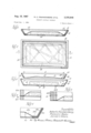
- FIGURE 1 is a cross-sectional view of a modular food frame in accordance with the present invention.
- FIGURE 2 is a plan view of the arangement shown in FIGURE 1;
- FIGURE 3 is a separated view in cross-section of the portions of the modular food frame shown in FIGURE 1;
- FIGURES 4, 5 and 6 are variations of the same arrangement shown in FIGURE 1;
- FIGURES 7, 8 and 9 illustrate arrangements of an alternative form of the food frame in accordance with the present invention.
- FIGURES 10 and 11 illustrate variations of the arrangement set forth in FIGURES l and 3, respectively;
- FIGURE 12 and FIGURUE 13 each illustrate further adaptations of the principles set forth in FIGURE 11;
- FIGURE 14 illustrates another locking arrangement that can be utilized in the arrangement of the invention.
- each of the top and bottom frames includes :a sheet of transparent or translucent film.
- FIGURES 1, 2 and 3 there is illustrated an arrangement including a shallow covered frame 10 and a mating covered frame 20.
- Each 0 fthe frames is substantially rectangular in configuration, although they could be circular or triangular or of any other suitable geometric design.
- the frame 10 includes a horizontal pan portion 11 and a surrounding rirn portion 12 integrally connected thereto. The uppermost portion of the rim 12 is surmounted by an inwardly extending lip 13.
- the pan portion 11 is made up of a sheet of transparent film 14- firmly secured to the bottom portions of the rim 12, and may, but not necessarily, include rib portions 15 integrally formed with the rim 12.
- the utilization of ribs 15 will depend in part on the characteristic of the film 14, on the size of the pan and on the anticipated load to be carried by the pan. Certainly, and for most circumstances, if a heavy cellophane or a plastic film were employed for the sheet 14-, in most usages the rib portions would not be required.
- the rim portion 12 in cross-section forms an obtuse angle with the pan portion 11 in order to permit nesting between a plurality of stacked frames 10 and also to accommodate therein the particularly formed frame
- the frame 20 includes a pan portion 21 and a rim portion 22 wherein the pan portion is comprised essentially of a sheet of transparent material 23 having preferably stretch characteristics. At its ends the sheet of transparent material 23 is rigidly secured to the rim 22 at the outside surfaces 24 thereof.
- the pan portion 21 may or may not include a horizontal flange section (not shown in FIGURES 1, 2 and 3, but as illustrated in FIGURE 14) formed integrally with the side walls of the rim 22. As illustrated the rim 22 is planar and forms an obtuse angle with the pan portion 21.
- the obtuse angle d formed between the rim 12 and the pan 11 of the frame 10 may be the same as the obtuse angle 1) formed between the rim 22 and the pan 21 of the tray 20. However, as shown in FIGURE 3, the angle a is larger than the angle b for reasons described hereinafter.
- the product to be packaged characterized by the numeral 30 is centered on the pan portion 14 of the frame 10 and the frame 20 is then placed down over the product 30 so as to cause the rim portions 22 of the frame 20 to nest against and contiguous to the rim por tion 12 of the frame 10.
- the flexible sheet 23 forming the pan portion of the frame 20 is made to overlie the product 3i ⁇ and where it has a stretchable characteristic to conform generally to the configuration of the product 30.
- the upper end of the rim 22 of the frame 20 locks against the under face of the lip 13 on the rim portion 12 of the frame 10.
- the meat is packaged in a system that is mechanically locked against easy opening and forces are applied against the product to maintain it in position in the package.
- the forces applied against the product 30 to maintain it in position on the frame 10 are, as best shown in FIG- URE 1, derived primarily through the dynamic action of the sheet 23 on the rim 22 of the frame 20.
- the sheet 23 is a stretchable film
- the film itself expands in a manner so as to accommodate the volume of the meat and to exert the restraining pressure upon it.
- the necessary flexibility in volume capacity for the package is achieved from a fiexnre in the rim portion 22 of the frame 20.
- the dimension of the pan portion 11 of the frame 10 is selected to be c
- the outside dimension of the pan 21 of the frame 20, including the wall thickness of the rim portion 22 at its bottom 24 should be selected to be of a dimension d greater than the dimension 0.
- the obtuse angle b between the pan 21 and the rim 22 of the frame 20 would be less than the obtuse angle a between the pan 11 and the rim 12 of the frame 10.
- a compressive force is applied to the bottom portion 24 of the rim 22 pulling that portion toward the center of the pan 21 and providing necessary slack in the film 23 for overlying the product 30.
- the upper portion 25 of the rim 22 is subjected to tensile forces tending to move the upper portions thereof away from the center of the frame 20 and expanding that dimension.
- the film 23 forming the pan portion 21 of the frame 20 overlies and conforms to the product 30,
- the frame 20 is securely locked into nesting position within the frame 10, and the more bulky the product 30, the greater the tension in the film 23, and correspondingly the greater the expansive forces on the upper portion 25 of the rim 22 and the greater the locking action between the two frames.
- this type of function requires that the rim 22 of the frame 20 is made of a flexible material which can respond to both compressive and tensile forces, and in that regard where flexible materials are employed for both frames 10 and 20, that the two frames may be hinged together for folding along a hinge line such as line 26 in FIGURE 2.
- FIGURE 3 is described in terms of the frame 20 being responsive to forces applied thereto, it is obvious that the invention is not limited to that concept and that the frame 20 can be formed so as to fit precisely within the dimensions provided on the inner surface of the rim 12 of the frame 10. In some circumstances it may prove of advantage to employ for the rim 22 of the frame 20 a rigid or semi-rigid material such as a plastic or a paper, whereupon it would be desirable to use a sheet 23 for the pan portion 21 which had a high capacity for stretch.
- a rigid or semi-rigid material such as a plastic or a paper
- the material used in the sheet 14 comprising the pan of the frame 10 can be of a more rigid material and the film forming the sheet 23 of the frame 20 can be a more flexible material and preferably of the stretchable type.
- the trays are to be utilized for the purposes of packaging meats, other characteristics for the sheets 14 and 23 are also important.
- Meats are most attractive to the purchaser when it displays a bloom usually characterized by a deep red appearance. To keep the meat attractive, this bloom should be retained in the meat during what is considered to be a normal shelf time between first display and final purchase. Bloom retention is dependent upon the meat retaining its moisture and also upon it having provided to it an adequate amount of oxygen. Accordingly, the ideal materials for both the sheets 14 and 23 is material which will transmit air but not moisture, that is, material having the characteristic of high gas transmission but low moisture vapor transmission.
- soft plastic films which display this characteristic of high gas transmission and low vapor transmission and, therefore, which are most adaptable for use in the packaging arrangements of the invention, are polyethylene, hydrochloride and polyvinyl chloride. When these are of the stretchable type, they are particularly well adapted to be used as sheet 23 in the frame 20 and in a more heavier formation they are adapted for use as a sheet 14 in a frame 10. As previously mentioned, treated cellophanes could also be used for at least a sheet 14 in the frame 10.
- FIGURES 4, 5, and 6 show variations of the netsing arrangements that can be employed for the otherwise general configuration shown in FIGURES 1, 2 and 3. That is, in FIGURE 4 the frame 20A can be nested to the bottom frame 10A in a top to bottom abutting arrangement. In this configuration the pair of frames are of identically the same linear dimensions. The frames are permanently nested to one another at the abutting edge 35 by means of an adhesive of any suitable form.
- FIGURE 5 shows a further variation in which the frame (20B is nested within the tray 1013 in a side wall to side wall abutting relationship and they are secured together, for example, by a crimped pin 37.
- FIGURE 6 is more nearly similar to the arrangement of FIGURE 1 except that both the frame 20C and the frame 10C include a pan rim 22C and 12C. In this instance there is an inwardly extending lip or flange on the frame 20C and the two frames are secured together in the nested position by means of a suitable adhesive applied between the contiguous surfaces of the films 23C and 11C.
- FIGURES 7 and 8 show configurations in which the upper nesting frame, nests exterior to the lowermost frame.
- the upper frame 20D nests around the exterior of the lower frame D so that the film portion 23D forms a cap or lid to the package structure.
- each of the frames 10D and 20D include a corresponding notch 39 and projection 41, respectively, for interlocking the two units.
- the bottom frame 10B is provided at its upper edge with an outwardly extending lip 13E and the top frame 20E is provided with an inwardly extending lip 43 which is formed to underlie and interlock with the lip 13E.
- the film 23F overlies the outside surface of the frame 20E.
- FIGURE 9 is a further variation of the structure of FIGURE 8, wherein the frame 10F has included a deep lip 13F that turns back on itself and the frame .20F is a horizontal rim with an upwardly extending flange 45, the flange of which fits into and interlocks with the deep lip 13F.
- the film 23F overlies the outside surface of the frame 20F.
- the top and/ or bottom frames are of a flexible construction to permit the top frames to be fitted over the bottom trays so that once interlocked the package must, for all practical purposes, be destroyed to separate the parts.
- the films in each of the structures 23D, 23E and 23F, respectively are stretched to accommodate a product that may extend above the uppermost level of the package structure, forces are exerted on the upper frames, 20D, 20E and 20F, respectively, and the corresponding bottom frames 10D, 10E and 10F, respectively, to cause the frame pairs to be more tightly interlocked against accidental opening.
- FIGURES 10 and 11 show additional variations from the arrangements of FIGURES 1 to 3, particularly as they might be applied to a prepackaging material made of expandable polystyrene.
- the frame 60 is formed of a rim 61 having a downward locking projection 62 on its inner surface.
- a sheet of film 64 which forms the cover for the frame.
- the nesting frame 70 is formed of a rim 71 which includes on its outer surface a correspondingly disposed notch 72 adapted to receive the projection 62 from the frame 60 and is reinforced at its upper end 73 and at its lower end 74.
- the purpose of the reinforcement at the ends 73 and 74 is to prevent as much as possible any change in dimensions of the frame 70 responsive to the application of compressive and tensile forces therein. Interlock between the two frames 60 and 70 is acheived by action between the projection 62 and the notch 7.2.
- FIGURE 12 The arrangement shown in FIGURE 12 is substantially the same as that shown in FIGURE 11 with the frame 60A in FIGURE 12 being identical to the frame 60 in FIG- URE 11.
- the frame 70A is modified only to the extent that the side wall is purposely bowed outwardly and the film 75 extends up the outside wall of the rim 71A to the attachment area 76 just below the notch 72A.
- This frame 70A is made of material which is flexible particularly in the midsection of the rim 71A.
- FIGURE 13 A further variation of the same arrangement shown in FIGURE 13 which might be formed from a rigid or semirigid plastic.
- the bottom frame 80 is formed in its rim 81 in an inward projection 82 and includes a cover film 83 attached thereto.
- the upper frame 90 at its rim 91 includes at its upper end a strengthening bead 93 and at its lower end a rigid strengthening bead 94.
- the rim 91 is inwardly concave and includes in this formation an inward projection 92.
- the film 95 which forms the pan portion of the tray 90 is carried around the bead 94 and up the external wall of the rim 91 and afi'ixed by means of adhesive or otherwise to the area 96 immediately below the inward projection 92.
- the wall of the rim 91 pops into an outer configuration as illustrated by the dotted lines in FIGURE 13.
- the rim 81 of the frame limits the movement of the rim 91 in the outward direction but in so doing causes a tight fit between the two frames and 80.
- FIGURE 14 is a further variation of the arrangement of FIGURE 1 in which the upper frame 20G is provided with an integrally formed projection 28 ridged or headed to include a head as shown, and in which the lower frame 106 includes in it a correspondingly formed cavity 18 into which the projection 28 flts and interlocks.
- a product display package comprising: a first frame structure, a second frame structure, each of said frame structures being made up of a rim portion and a cover portion, said cover portion of each of said first and second frame structures being integrally connected to the rim portion thereof and including a sheet of light-transmitting load bearing material, said first frame structure constituting a shallow tray for receiving therein the product to be packaged and for which the rim portion extends outwardly from the bottom of the tray, said second frame structure constituting an enclosure for said first frame structure and for which the rim portion carries the cover portion at the top thereof and for which the rim portion projects inwardly from its top to bottom of the enclosure, to overlie and to conform at its interior mating surface to the rim portion of said first frame at its exterior mating surface, one of said frame structure including a projection on the mating surface of its rim portion, the other one of said frame structures including a receiving cavity on the mating surface of its rim portion, whereby upon nesting of said second frame structure onto said first frame structure said package is unitari
- a product display package comprising: a first frame structure, a second frame structure, each of said frame structures being made up of a rim portion and a cover portion, said cover portion of each of said first and second frame structures being integrally connected to the rim portion thereof and including a sheet of light transmitting load bearing material, said frame structures being formed so as to engage one another contiguously at the rim portions thereof with the cover portions thereof overlying one another, and cooperating means at the contiguous rim portions for securing said first and second frame structures together, comprising interlocking projections and cavities, whereby a product supported in said packaging arrangement between said cover portions of said secured together first and second frame structures is retained immobile thereon by the tensions exerted thereon by said sheets.
- a product display package comprising: a first frame structure, a second frame structure, each of said frame structures being made up of a rim portion and a cover portion, said cover portion of each of said first and second frame structures being integrally connected to the rim portion thereof and including a sheet of light transmitting load bearing material, said frame structures being formed so as to engage one another contiguously at the rim portions thereof with the cover portions thereof overlying one another, and cooperating means at the contiguous rim portions for securing said first and second frame structures together, comprising pinning devices, whereby a product supported in said packaging arrangement between said cover portions of said secured together first and second frame structures is retained immobile there on by the tensions exerted thereon by said sheets.
- a product display package comprising: a first frame structure, a second frame structure, each of said frame structures being made up of a rim portion and a cover portion, said cover portion of each of said first and second frame structures being integrally connected to the rim portion thereof and including a sheet of light transmitting load bearing material, said first frame structure constituting a shallow tray for receiving therein the product to be packaged and for which the rim portion extends outwardly from the bottom of the tray, said second frame structure constituting a closure for said first frame structure and for which the rim portion carries the cover portion at the bottom thereof and for which the rim portion projects outwardly from its bottom to top to overlie and to conform at its exterior mating surface to the rim portion of said first frame at its interior mating surface, means at the mating surfaces of the rim portions for securing said first and second frame structures together, comprising a lip on said first frame structure which overlies the top of the rim portion of said second frame structure, whereby upon nesting of said second frame structure onto said first frame structure said package is unit
Description
g- 1967 R. c. FRANKELNBERG ETAL PRODUCT DISPLAY PACKAGE 2 Sheets-Sheet 1 Filed Dec. 7, 1964 5 w Z n fm m M w fimwz 6222/22 Jar/266 6. 12161572,
g- 15, 1967 R. c. FRANKENBERG ETAL 3,335,848
PRODUCT DISPLAY PACKAGE Filed Dec. 7, 1964 2 Sheets-Sheet 2 avg...
Babe/Z Cffan/Zembe 1722 new L.
Ja 6 CA 7 06472, M; @m KLZ W 71 W 3,335,848 PRODUCT DISPLAY PACKAGE Robert C. Frankenberg, 311 S. Edward, Mount Prospect,
Ill. 60056; Francis L. Stahr, 214 Maple Road, Barrington, 11]. 60010; and James C. Tobin, 1257 Pine, Glenview, Ill. 60025 Filed Dec. 7, 1964, Ser. No. 416,580 6 Claims. (Cl. 206-4534) ABSTRACT OF THE DISCLOSURE A product display package including interlocking first and second frame instructu-res, each frame structure having a sheet of light transmitting load bearing material, the frame structures being formed to engage one another contiguously at their rim portions, the product being retained immobily in the display package by the sheets.
The present invention relates to a product display package and in particular to a modular food tray for displaying and preserving perishable food products.
In recent years, the methods employed in the marketing of perishable products, including vegetables and meats, have changed from the individual-counter service type sales to the prepackaged self-service display type sales. Specifically, and by way of ilustration, prepacking methods presently employed for the wrapping and display of meat products, for example, prescribes the butchering of the animal carcass into the individual cuts of meat, placing those cuts of meat on individual paperboard, plastic, or pulp trays, or die cut boards overwrapping the cut of meat on the tray or board with a trasparen-t film, such as cellophane, rubber hydrochloride, polyethylene, polyolefins, polyvinyl chloride or like films, and heat sealing the folds of the sheet of film to itself on the bottom side of the tray.
This type of packaging in its most rudimentary form is hand-wrapped and heat sealed using a hot plate or hand iron, and in the most elaborate form is done automaticaly with wrapping machines. The former method, inasmuch as it is done by hand, is dependent for its success upon the skill or physio-motor ability of the packager in seeing to it that the package is properly sealed without the package being burned or the package being ruptured. The latter method of employing automatic equipment is most satisfactory in its operation but does require a substantial investment in money and is suited only for the large volume types of packaging operations.
Another disadvantage of this type of prepackaging is that the tray used is in most instances completely opaque and even in those instances where a transparent or translucent tray is employed, the multiple fold of film on the bottom side of the tray in the area of heat sealing so distorts the transparency as to render the bottom of the tray, for all practical purposes, substantially opaque. This is significant, particularly in the marketing of meat products, because the purchaser is impressed by, and purchases mainly on the strength of, the appearance of the meat. To the wise purchaser, a display of just one side of the cut is considered to tell less than half the story because in most marketing operations, the purchaser assumes that the best side of the meat is placed face up and the worst side of the meat is placed face down on the tray. This is so widely recognized as a truism that some merchandisers having no way of adequately display both sides of the prepackaged product and having no other way to combat this suspicion, have been led to advertise that in their packaged products, the worts side of the product is packaged face up. Thus this problem of adequately dis- 3,335,848 Patented Aug. 15, 1967 playing prepackaged meats is a real and continuing one, and a problem to which this invention directs itself.
It is the object of the present invention to provide a new and improved packaging system for perishable foods, such as meats, which will provide a clear and convenient display of both sides of a cut of meat. It is a further ob ject of the invention to provide a high visibility packaging arrangement which is as rigid and strong as it is visible and provides at the same time, adequate protection for the meat when on display and when being handled in the market.
A further object of the invention is to provide a rigid strong maxi-mum visibility packaging system which can be manually executed without danger to the packager or without the requirement of expensive equipment.
A more specific object of the invention is to provide a proper display package made up of a pair of cooperating frames or shallow trays type structures wherein the pan portion of each frame may be a layer of light transmitting load bearing material and wherein the material for one of said frames may be of the flexible type.
A further specific object of the invention is to provide a packaging system including a pair of cooperating covered frame wherein the frames can be adapted to accommodate different heights and volumes of product by variating the amount and type of stretchable material or film used in covering the frames.
Further objects and features of the invention pertain to the particular arrangement and structure whereby the above identified and other objects of the inventon are attained. The invention, both as to its structure and mode of operation, will be better understood by reference to the following specification and drawings, forming a part thereof, wherein:
FIGURE 1 is a cross-sectional view of a modular food frame in accordance with the present invention;
FIGURE 2 is a plan view of the arangement shown in FIGURE 1;
FIGURE 3 is a separated view in cross-section of the portions of the modular food frame shown in FIGURE 1;
FIGURES 4, 5 and 6 are variations of the same arrangement shown in FIGURE 1;
FIGURES 7, 8 and 9 illustrate arrangements of an alternative form of the food frame in accordance with the present invention;
FIGURES 10 and 11 illustrate variations of the arrangement set forth in FIGURES l and 3, respectively;
FIGURE 12 and FIGURUE 13 each illustrate further adaptations of the principles set forth in FIGURE 11; and
FIGURE 14 illustrates another locking arrangement that can be utilized in the arrangement of the invention.
Referring to the drawings, there is shown therein a packaging arrangement which is basically an interlocking top and bottom framework wherein each of the top and bottom frames includes :a sheet of transparent or translucent film. Turning specifically to FIGURES 1, 2 and 3, and as best shown in FIGUURE 3, there is illustrated an arrangement including a shallow covered frame 10 and a mating covered frame 20. Each 0 fthe frames is substantially rectangular in configuration, although they could be circular or triangular or of any other suitable geometric design. The frame 10 includes a horizontal pan portion 11 and a surrounding rirn portion 12 integrally connected thereto. The uppermost portion of the rim 12 is surmounted by an inwardly extending lip 13.
The pan portion 11 is made up of a sheet of transparent film 14- firmly secured to the bottom portions of the rim 12, and may, but not necessarily, include rib portions 15 integrally formed with the rim 12. The utilization of ribs 15 will depend in part on the characteristic of the film 14, on the size of the pan and on the anticipated load to be carried by the pan. Certainly, and for most circumstances, if a heavy cellophane or a plastic film were employed for the sheet 14-, in most usages the rib portions would not be required. The rim portion 12 in cross-section forms an obtuse angle with the pan portion 11 in order to permit nesting between a plurality of stacked frames 10 and also to accommodate therein the particularly formed frame The frame 20 includes a pan portion 21 and a rim portion 22 wherein the pan portion is comprised essentially of a sheet of transparent material 23 having preferably stretch characteristics. At its ends the sheet of transparent material 23 is rigidly secured to the rim 22 at the outside surfaces 24 thereof. The pan portion 21 may or may not include a horizontal flange section (not shown in FIGURES 1, 2 and 3, but as illustrated in FIGURE 14) formed integrally with the side walls of the rim 22. As illustrated the rim 22 is planar and forms an obtuse angle with the pan portion 21. The obtuse angle d formed between the rim 12 and the pan 11 of the frame 10 may be the same as the obtuse angle 1) formed between the rim 22 and the pan 21 of the tray 20. However, as shown in FIGURE 3, the angle a is larger than the angle b for reasons described hereinafter.
In utilizing the frame arrangement shown in FIGURES 1, 2 and 3, the product to be packaged characterized by the numeral 30 is centered on the pan portion 14 of the frame 10 and the frame 20 is then placed down over the product 30 so as to cause the rim portions 22 of the frame 20 to nest against and contiguous to the rim por tion 12 of the frame 10. In so doing, the flexible sheet 23 forming the pan portion of the frame 20 is made to overlie the product 3i} and where it has a stretchable characteristic to conform generally to the configuration of the product 30. When in place and as best shown by FIGURE 1, the upper end of the rim 22 of the frame 20 locks against the under face of the lip 13 on the rim portion 12 of the frame 10. Thus, the meat is packaged in a system that is mechanically locked against easy opening and forces are applied against the product to maintain it in position in the package.
The forces applied against the product 30 to maintain it in position on the frame 10 are, as best shown in FIG- URE 1, derived primarily through the dynamic action of the sheet 23 on the rim 22 of the frame 20. Where the sheet 23 is a stretchable film, the film itself expands in a manner so as to accommodate the volume of the meat and to exert the restraining pressure upon it.
Of course, it may be that it is preferred not to use a stretchable film or to use a film of a greater thickness wherein the amount of stretch is actually limited. In such case, the necessary flexibility in volume capacity for the package is achieved from a fiexnre in the rim portion 22 of the frame 20. Specifically, and as shown in FIGURE 3, if the dimension of the pan portion 11 of the frame 10 is selected to be c, then the outside dimension of the pan 21 of the frame 20, including the wall thickness of the rim portion 22 at its bottom 24 should be selected to be of a dimension d greater than the dimension 0. In this circumstance and as previously referred to, the obtuse angle b between the pan 21 and the rim 22 of the frame 20 would be less than the obtuse angle a between the pan 11 and the rim 12 of the frame 10. Thus, when the frame 20 is nested into the frame 10*, and the film 23 overlies and conforms to the product 39, a compressive force is applied to the bottom portion 24 of the rim 22 pulling that portion toward the center of the pan 21 and providing necessary slack in the film 23 for overlying the product 30. By the same action, the upper portion 25 of the rim 22 is subjected to tensile forces tending to move the upper portions thereof away from the center of the frame 20 and expanding that dimension. Thus, the film 23 forming the pan portion 21 of the frame 20 overlies and conforms to the product 30,
the upper portion 25 of the rim 22 is forced outwardly against the side walls of the pan portion 12 of the frame It) and under the lip 13 formed thereon. Thus, the frame 20 is securely locked into nesting position within the frame 10, and the more bulky the product 30, the greater the tension in the film 23, and correspondingly the greater the expansive forces on the upper portion 25 of the rim 22 and the greater the locking action between the two frames. It is obvious, of course, that this type of function requires that the rim 22 of the frame 20 is made of a flexible material which can respond to both compressive and tensile forces, and in that regard where flexible materials are employed for both frames 10 and 20, that the two frames may be hinged together for folding along a hinge line such as line 26 in FIGURE 2.
Although FIGURE 3 is described in terms of the frame 20 being responsive to forces applied thereto, it is obvious that the invention is not limited to that concept and that the frame 20 can be formed so as to fit precisely within the dimensions provided on the inner surface of the rim 12 of the frame 10. In some circumstances it may prove of advantage to employ for the rim 22 of the frame 20 a rigid or semi-rigid material such as a plastic or a paper, whereupon it would be desirable to use a sheet 23 for the pan portion 21 which had a high capacity for stretch.
It has already been stated that the material used in the sheet 14 comprising the pan of the frame 10 can be of a more rigid material and the film forming the sheet 23 of the frame 20 can be a more flexible material and preferably of the stretchable type. Where the trays are to be utilized for the purposes of packaging meats, other characteristics for the sheets 14 and 23 are also important.
Meats are most attractive to the purchaser when it displays a bloom usually characterized by a deep red appearance. To keep the meat attractive, this bloom should be retained in the meat during what is considered to be a normal shelf time between first display and final purchase. Bloom retention is dependent upon the meat retaining its moisture and also upon it having provided to it an adequate amount of oxygen. Accordingly, the ideal materials for both the sheets 14 and 23 is material which will transmit air but not moisture, that is, material having the characteristic of high gas transmission but low moisture vapor transmission.
Two examples of soft plastic films which display this characteristic of high gas transmission and low vapor transmission and, therefore, which are most adaptable for use in the packaging arrangements of the invention, are polyethylene, hydrochloride and polyvinyl chloride. When these are of the stretchable type, they are particularly well adapted to be used as sheet 23 in the frame 20 and in a more heavier formation they are adapted for use as a sheet 14 in a frame 10. As previously mentioned, treated cellophanes could also be used for at least a sheet 14 in the frame 10.
FIGURES 4, 5, and 6 show variations of the netsing arrangements that can be employed for the otherwise general configuration shown in FIGURES 1, 2 and 3. That is, in FIGURE 4 the frame 20A can be nested to the bottom frame 10A in a top to bottom abutting arrangement. In this configuration the pair of frames are of identically the same linear dimensions. The frames are permanently nested to one another at the abutting edge 35 by means of an adhesive of any suitable form.
FIGURE 5 shows a further variation in which the frame (20B is nested within the tray 1013 in a side wall to side wall abutting relationship and they are secured together, for example, by a crimped pin 37.
The arrangement of FIGURE 6 is more nearly similar to the arrangement of FIGURE 1 except that both the frame 20C and the frame 10C include a pan rim 22C and 12C. In this instance there is an inwardly extending lip or flange on the frame 20C and the two frames are secured together in the nested position by means of a suitable adhesive applied between the contiguous surfaces of the films 23C and 11C.
The arrangements of FIGURES 7 and 8 show configurations in which the upper nesting frame, nests exterior to the lowermost frame. Specifically, in FIGURE 7 the upper frame 20D nests around the exterior of the lower frame D so that the film portion 23D forms a cap or lid to the package structure. As shown, each of the frames 10D and 20D include a corresponding notch 39 and projection 41, respectively, for interlocking the two units. In the arrangement of FIGURE 8, the bottom frame 10B is provided at its upper edge with an outwardly extending lip 13E and the top frame 20E is provided with an inwardly extending lip 43 which is formed to underlie and interlock with the lip 13E. The film 23F overlies the outside surface of the frame 20E.
The arrangement of FIGURE 9 is a further variation of the structure of FIGURE 8, wherein the frame 10F has included a deep lip 13F that turns back on itself and the frame .20F is a horizontal rim with an upwardly extending flange 45, the flange of which fits into and interlocks with the deep lip 13F. Here the film 23F overlies the outside surface of the frame 20F.
In the arrangements of FIGURES 7, 8 and 9 the top and/ or bottom frames are of a flexible construction to permit the top frames to be fitted over the bottom trays so that once interlocked the package must, for all practical purposes, be destroyed to separate the parts. But in addition, as the films in each of the structures 23D, 23E and 23F, respectively, are stretched to accommodate a product that may extend above the uppermost level of the package structure, forces are exerted on the upper frames, 20D, 20E and 20F, respectively, and the corresponding bottom frames 10D, 10E and 10F, respectively, to cause the frame pairs to be more tightly interlocked against accidental opening.
FIGURES 10 and 11 show additional variations from the arrangements of FIGURES 1 to 3, particularly as they might be applied to a prepackaging material made of expandable polystyrene. In the arrangements of FIG- URES 10 and 11, the frame 60 is formed of a rim 61 having a downward locking projection 62 on its inner surface. At its bottom portion 63 there is aflixed a sheet of film 64 which forms the cover for the frame. The nesting frame 70 is formed of a rim 71 which includes on its outer surface a correspondingly disposed notch 72 adapted to receive the projection 62 from the frame 60 and is reinforced at its upper end 73 and at its lower end 74. The purpose of the reinforcement at the ends 73 and 74 is to prevent as much as possible any change in dimensions of the frame 70 responsive to the application of compressive and tensile forces therein. Interlock between the two frames 60 and 70 is acheived by action between the projection 62 and the notch 7.2.
The arrangement shown in FIGURE 12 is substantially the same as that shown in FIGURE 11 with the frame 60A in FIGURE 12 being identical to the frame 60 in FIG- URE 11. The frame 70A is modified only to the extent that the side wall is purposely bowed outwardly and the film 75 extends up the outside wall of the rim 71A to the attachment area 76 just below the notch 72A. This frame 70A is made of material which is flexible particularly in the midsection of the rim 71A.
In the arrangement of FIGURE 12 the mating of the frame 7A into the frame 6A causes a very tight fit between the two frames particularly at the interlock between the projection 62A and the notch 72A. Further, stretching action in the sheet 75 in overlying the product to be covered causes forces to be applied to the outer wall of the rim 71A at the area 76 thereby tending to move the midportion of the rim 71A in an outward direction. Thus, the tighter the film 75 is stretched over the product the greater the tendency of the rim 71A to be expanded outwardly and the greater the interlock between the projection 62A and the notch 72A.
A further variation of the same arrangement shown in FIGURE 13 which might be formed from a rigid or semirigid plastic. Therein the bottom frame 80 is formed in its rim 81 in an inward projection 82 and includes a cover film 83 attached thereto. The upper frame 90 at its rim 91 includes at its upper end a strengthening bead 93 and at its lower end a rigid strengthening bead 94. In its central portion the rim 91 is inwardly concave and includes in this formation an inward projection 92. At the same time the film 95 which forms the pan portion of the tray 90 is carried around the bead 94 and up the external wall of the rim 91 and afi'ixed by means of adhesive or otherwise to the area 96 immediately below the inward projection 92. In this configuration where the frame 90 is formed of material of the resilient type, nesting of the frame 90 into the frame 80 with the film 95 in stretched extension over a product to be packaged, a force is exerted on the outside wall of the rim 91 at the area 96 by the film 95 actually moving the wall in the outward direction.
Thus, the wall of the rim 91 pops into an outer configuration as illustrated by the dotted lines in FIGURE 13. The rim 81 of the frame limits the movement of the rim 91 in the outward direction but in so doing causes a tight fit between the two frames and 80.
The arrangement of FIGURE 14 is a further variation of the arrangement of FIGURE 1 in which the upper frame 20G is provided with an integrally formed projection 28 ridged or headed to include a head as shown, and in which the lower frame 106 includes in it a correspondingly formed cavity 18 into which the projection 28 flts and interlocks.
From the foregoing it is clear that there has been pro vided herewith a new and improved packaging system and various arrangements therefor which permits not only clean display of the products so packaged but also the packaging may be accomplished entirely by manual means in an inexpensive yet expeditious way. The examples given herein are merely by way of illustration of the conception of the invention and it is clear that many modifications and changes may be made therein without departing from the spirit thereof. Accordingly, it is intended to cover within the appended claims all such variations and changes and modifications as fall within the true spirit and scope of the invention.
What is claimed is:
1. A product display package comprising: a first frame structure, a second frame structure, each of said frame structures being made up of a rim portion and a cover portion, said cover portion of each of said first and second frame structures being integrally connected to the rim portion thereof and including a sheet of light-transmitting load bearing material, said first frame structure constituting a shallow tray for receiving therein the product to be packaged and for which the rim portion extends outwardly from the bottom of the tray, said second frame structure constituting an enclosure for said first frame structure and for which the rim portion carries the cover portion at the top thereof and for which the rim portion projects inwardly from its top to bottom of the enclosure, to overlie and to conform at its interior mating surface to the rim portion of said first frame at its exterior mating surface, one of said frame structure including a projection on the mating surface of its rim portion, the other one of said frame structures including a receiving cavity on the mating surface of its rim portion, whereby upon nesting of said second frame structure onto said first frame structure said package is unitarily locked at said projections and cavities.
2. The product display package set forth in claim 1 wherein the sheet of material in said second frame structure is of the stretchable type and upon being stretched in the packaging of a product exerts greater locking pressures between rim portions of the first and second tray structures.
3. A product display package comprising: a first frame structure, a second frame structure, each of said frame structures being made up of a rim portion and a cover portion, said cover portion of each of said first and second frame structures being integrally connected to the rim portion thereof and including a sheet of light transmitting load bearing material, said frame structures being formed so as to engage one another contiguously at the rim portions thereof with the cover portions thereof overlying one another, and cooperating means at the contiguous rim portions for securing said first and second frame structures together, comprising interlocking projections and cavities, whereby a product supported in said packaging arrangement between said cover portions of said secured together first and second frame structures is retained immobile thereon by the tensions exerted thereon by said sheets.
4. A product display package comprising: a first frame structure, a second frame structure, each of said frame structures being made up of a rim portion and a cover portion, said cover portion of each of said first and second frame structures being integrally connected to the rim portion thereof and including a sheet of light transmitting load bearing material, said frame structures being formed so as to engage one another contiguously at the rim portions thereof with the cover portions thereof overlying one another, and cooperating means at the contiguous rim portions for securing said first and second frame structures together, comprising pinning devices, whereby a product supported in said packaging arrangement between said cover portions of said secured together first and second frame structures is retained immobile there on by the tensions exerted thereon by said sheets.
5. A product display package comprising: a first frame structure, a second frame structure, each of said frame structures being made up of a rim portion and a cover portion, said cover portion of each of said first and second frame structures being integrally connected to the rim portion thereof and including a sheet of light transmitting load bearing material, said first frame structure constituting a shallow tray for receiving therein the product to be packaged and for which the rim portion extends outwardly from the bottom of the tray, said second frame structure constituting a closure for said first frame structure and for which the rim portion carries the cover portion at the bottom thereof and for which the rim portion projects outwardly from its bottom to top to overlie and to conform at its exterior mating surface to the rim portion of said first frame at its interior mating surface, means at the mating surfaces of the rim portions for securing said first and second frame structures together, comprising a lip on said first frame structure which overlies the top of the rim portion of said second frame structure, whereby upon nesting of said second frame structure onto said first frame structure said package is unitarily locked.
6. The product display package of claim 5 wherein said sheet of material in said second frame structure is of the stretchable type and upon stretching of the sheet in the covering of a product expands the top of the rim portion of said second frame structure tightly under the lip of said first frame structure.
References Cited UNITED STATES PATENTS 2,080,125 5/1937 Frost 20645.32 2,134,908 11/1938 Copeman 21735 2,157,407 5/1939 Frost 20645.32 2,754,959 7/ 1956 McCarty 206-45.33
THERON E. CONDON, Primary Examiner.
WILLIAM T. DIXSON, JR., Examiner.
Claims (1)
1. A PRODUCT DISPLAY PACKAGE COMPRISING: A FIRST FRAME STRUCTURE, A SECOND FRAME STRUCTURE, EACH OF SAID FRAME STRUCTURES BEING MADE UP OF A RIM PORTION AND A COVER PORTION, SAID COVER PORTION OF EACH OF SAID FIRST AND SECOND FRAME STRUCTURES BEING INTEGRALLY CONNECTED TO THE RIM PORTION THEREOF AND INCLUDING A SHEET OF LIGHT-TRANSMITTING LOAD BEARING MATERIAL, SAID FIRST FRAME STRUCTURE CONSTITUTING A SHALLOW TRAY FOR RECEIVING THEREIN THE PRODUCT TO BE PACKAGED AND FOR WHICH THE RIM PORTION EXTENDS OUTWARDLY FROM THE BOTTOM OF THE TRAY, SAID SECOND FRAME STRUCTURE CONSTITUTING AN ENCLOSURE FOR SAID FIRST FRAME STRUCTURE AND FOR WHICH THE RIM PORTION CARRIES THE COVER PORTION AT THE TOP THEREOF AND FOR WHICH THE RIM PORTION PROJECTS INWARDLY FROM ITS TOP TO BOTTOM OF THE ENCLOSURE, TO OVERLIE AND TO CONFORM AT ITS INTERIOR MATING SURFACE TO THE RIM PORTION OF SAID FIRST FRAME AT ITS EXTERIOR MATING SURFACE, ONE OF SAID FRAME STRUCTURE INCLUDING A PROJECTION ON THE MATING SURFACE OF ITS RIM PORTION, THE OTHER ONE OF SAID FRAME STRUCTURES INCLUDING A RECEIVING CAVITY ON THE MATING SURFACE OF ITS RIM PORTION, WHEREBY UPON NESTING OF SAID SECOND FRAME STRUCTURE ONTO SAID FIRST FRAME STRUCTURE SAID PACKAGE IS UNITARILY LOCKED AT SAID PROJECTIONS AND CAVITIES.
Priority Applications (1)
| Application Number | Priority Date | Filing Date | Title |
|---|---|---|---|
| US416580A US3335848A (en) | 1964-12-07 | 1964-12-07 | Product display package |
Applications Claiming Priority (1)
| Application Number | Priority Date | Filing Date | Title |
|---|---|---|---|
| US416580A US3335848A (en) | 1964-12-07 | 1964-12-07 | Product display package |
Publications (1)
| Publication Number | Publication Date |
|---|---|
| US3335848A true US3335848A (en) | 1967-08-15 |
Family
ID=23650525
Family Applications (1)
| Application Number | Title | Priority Date | Filing Date |
|---|---|---|---|
| US416580A Expired - Lifetime US3335848A (en) | 1964-12-07 | 1964-12-07 | Product display package |
Country Status (1)
| Country | Link |
|---|---|
| US (1) | US3335848A (en) |
Cited By (5)
| Publication number | Priority date | Publication date | Assignee | Title |
|---|---|---|---|---|
| US4448311A (en) * | 1983-01-24 | 1984-05-15 | Tech Ref, Inc. | Sample cell |
| US5061501A (en) * | 1987-10-09 | 1991-10-29 | Lowe David M | Display package for meat item |
| US5076436A (en) * | 1982-11-15 | 1991-12-31 | W. R. Grace & Co.-Conn. | Vacuum packaging |
| USD830743S1 (en) | 2017-09-22 | 2018-10-16 | Tynies, Inc. | Display frame |
| US10321772B2 (en) | 2015-10-23 | 2019-06-18 | Tynies, Inc. | Display device and methods of use |
Citations (4)
| Publication number | Priority date | Publication date | Assignee | Title |
|---|---|---|---|---|
| US2080125A (en) * | 1932-12-16 | 1937-05-11 | George S Frost | Pie package |
| US2134908A (en) * | 1935-12-23 | 1938-11-01 | Copeman Lab Co | Package structure |
| US2157407A (en) * | 1935-02-01 | 1939-05-09 | Theodora B Frost | Package |
| US2754959A (en) * | 1953-02-25 | 1956-07-17 | Roland W Miller Sr | Display package with transparent cover |
-
1964
- 1964-12-07 US US416580A patent/US3335848A/en not_active Expired - Lifetime
Patent Citations (4)
| Publication number | Priority date | Publication date | Assignee | Title |
|---|---|---|---|---|
| US2080125A (en) * | 1932-12-16 | 1937-05-11 | George S Frost | Pie package |
| US2157407A (en) * | 1935-02-01 | 1939-05-09 | Theodora B Frost | Package |
| US2134908A (en) * | 1935-12-23 | 1938-11-01 | Copeman Lab Co | Package structure |
| US2754959A (en) * | 1953-02-25 | 1956-07-17 | Roland W Miller Sr | Display package with transparent cover |
Cited By (5)
| Publication number | Priority date | Publication date | Assignee | Title |
|---|---|---|---|---|
| US5076436A (en) * | 1982-11-15 | 1991-12-31 | W. R. Grace & Co.-Conn. | Vacuum packaging |
| US4448311A (en) * | 1983-01-24 | 1984-05-15 | Tech Ref, Inc. | Sample cell |
| US5061501A (en) * | 1987-10-09 | 1991-10-29 | Lowe David M | Display package for meat item |
| US10321772B2 (en) | 2015-10-23 | 2019-06-18 | Tynies, Inc. | Display device and methods of use |
| USD830743S1 (en) | 2017-09-22 | 2018-10-16 | Tynies, Inc. | Display frame |
Similar Documents
| Publication | Publication Date | Title |
|---|---|---|
| US3610510A (en) | Plastic,heart-shaped box | |
| US3292810A (en) | Multipacks for perishable merchandise | |
| US3676159A (en) | Thermoformed reusable package having a reclosable lid | |
| US3401827A (en) | Removable container lid with integral folding handle | |
| US3604614A (en) | Sleeve blank | |
| US4759444A (en) | Packaging of plant tissue | |
| US3257062A (en) | Hermetically sealed transparent shock absorbing package for fragile articles | |
| US4230729A (en) | One piece, collapsible package | |
| US3703383A (en) | Food product package | |
| US3051584A (en) | Bacon apckage | |
| US3351265A (en) | Container and closure | |
| JPH05506831A (en) | Package with colored wrapping | |
| US2652335A (en) | Package | |
| US11180275B2 (en) | Compartmentalized containers | |
| US20190233157A1 (en) | Packaging system and method | |
| GB1417234A (en) | Heat and serve packages for meat products | |
| US3464618A (en) | Reinforced-rim pocket pack of thin plastic material,for few fruits or like articles | |
| US3335848A (en) | Product display package | |
| US2703287A (en) | Soft plastic food package | |
| US3184047A (en) | Tray | |
| JP2684022B2 (en) | Strawberry packaging | |
| US3129866A (en) | Egg carton | |
| US3866817A (en) | Plastic packaging tray, particularly for bananas | |
| US3086646A (en) | Fruit and vegetable container | |
| US2763422A (en) | Packing device |
Legal Events
| Date | Code | Title | Description |
|---|---|---|---|
| AS | Assignment |
Owner name: FIGGIE INTERNATIONAL INC. Free format text: CHANGE OF NAME;ASSIGNOR:A-T-O INC.;REEL/FRAME:003866/0442 Effective date: 19810623 |