US3335781A - Burner control system - Google Patents
Burner control system Download PDFInfo
- Publication number
- US3335781A US3335781A US541657A US54165766A US3335781A US 3335781 A US3335781 A US 3335781A US 541657 A US541657 A US 541657A US 54165766 A US54165766 A US 54165766A US 3335781 A US3335781 A US 3335781A
- Authority
- US
- United States
- Prior art keywords
- relay
- burner
- safety switch
- winding
- switch
- Prior art date
- Legal status (The legal status is an assumption and is not a legal conclusion. Google has not performed a legal analysis and makes no representation as to the accuracy of the status listed.)
- Expired - Lifetime
Links
Images
Classifications
-
- F—MECHANICAL ENGINEERING; LIGHTING; HEATING; WEAPONS; BLASTING
- F23—COMBUSTION APPARATUS; COMBUSTION PROCESSES
- F23N—REGULATING OR CONTROLLING COMBUSTION
- F23N5/00—Systems for controlling combustion
- F23N5/20—Systems for controlling combustion with a time programme acting through electrical means, e.g. using time-delay relays
- F23N5/203—Systems for controlling combustion with a time programme acting through electrical means, e.g. using time-delay relays using electronic means
-
- F—MECHANICAL ENGINEERING; LIGHTING; HEATING; WEAPONS; BLASTING
- F23—COMBUSTION APPARATUS; COMBUSTION PROCESSES
- F23N—REGULATING OR CONTROLLING COMBUSTION
- F23N5/00—Systems for controlling combustion
- F23N5/02—Systems for controlling combustion using devices responsive to thermal changes or to thermal expansion of a medium
- F23N5/08—Systems for controlling combustion using devices responsive to thermal changes or to thermal expansion of a medium using light-sensitive elements
- F23N5/082—Systems for controlling combustion using devices responsive to thermal changes or to thermal expansion of a medium using light-sensitive elements using electronic means
-
- F—MECHANICAL ENGINEERING; LIGHTING; HEATING; WEAPONS; BLASTING
- F23—COMBUSTION APPARATUS; COMBUSTION PROCESSES
- F23N—REGULATING OR CONTROLLING COMBUSTION
- F23N2231/00—Fail safe
- F23N2231/04—Fail safe for electrical power failures
-
- F—MECHANICAL ENGINEERING; LIGHTING; HEATING; WEAPONS; BLASTING
- F23—COMBUSTION APPARATUS; COMBUSTION PROCESSES
- F23N—REGULATING OR CONTROLLING COMBUSTION
- F23N2233/00—Ventilators
- F23N2233/06—Ventilators at the air intake
-
- F—MECHANICAL ENGINEERING; LIGHTING; HEATING; WEAPONS; BLASTING
- F23—COMBUSTION APPARATUS; COMBUSTION PROCESSES
- F23N—REGULATING OR CONTROLLING COMBUSTION
- F23N2239/00—Fuels
- F23N2239/06—Liquid fuels
-
- F—MECHANICAL ENGINEERING; LIGHTING; HEATING; WEAPONS; BLASTING
- F23—COMBUSTION APPARATUS; COMBUSTION PROCESSES
- F23N—REGULATING OR CONTROLLING COMBUSTION
- F23N5/00—Systems for controlling combustion
- F23N5/02—Systems for controlling combustion using devices responsive to thermal changes or to thermal expansion of a medium
- F23N5/08—Systems for controlling combustion using devices responsive to thermal changes or to thermal expansion of a medium using light-sensitive elements
Definitions
- This invention relates to automatic electrical control ⁇ systems for fluid fuel burners which upon closure of a space thermostat supply fuel to the burner and render operative means to ignite it, and which include safety time switch means operative to permit the continued supply of fuel when there is combustion and to cut off the supply of fuel after a predetermined short time interval if combustion fails to occur or having occurred subsequently fails.
- An object of the invention is to provide a generally new and improved electrical control system for uid fuel burners having safety time switch means including an electrical resistance heater which -when energized for a predetermined short time effects opening of the safety switch and cuts off the supply of fuel to the burner, in which solid state switching means under control of photoconductive, combustion llame ⁇ sensing means controls energization of the safety time switch heating means, and in which a scavenging time switch delays restarting of the fuel supply following a cutoff thereof due to momentary electrical power failure.
- a further object is to provide a safety control system of the above character in which the solid state switching means is normally conductive only during the ⁇ short time interval between closure of the thermostat and the establishment of combustion flame or which, in event combustion does not occur or subsequently fails, is conductive only for the short period of time required to effect opening of the safety switch.
- a further object is to provide a safety control system of the above character in which the solid state switching device is connected in series with the safety switch heater across the electrical power supply at all times when the thermostat is closed, whereby faulty conduction through the solid state switching device wi-ll effect opening of the safety switch.
- the primary elements of the system include an oil burner having a driving motor 12, a space thermostat 14, a motor relay having a winding 16 and two sets of normally open contacts 18 and 22, a normally closed thermal time switch 24 (safety switch) including an electrical resistance heater 26, a photoconductive element 28, a silicon-controlled rectifier 30 (SCR) having a gate lead 31 and 'a gate control network comprising the photoconductive element '28, an adjustable resistor 32 with sliding contact 34 and a fixed resistor 36, a capacitor 38, a normally closed scavenging time switch 42 including 'an' electrical resistance heater 44, a spark igniter comprising "electrodes 52 and a voltage step-up transformer 54, a voltage step-down, power source transformer having a primary winding 56 and a secondary winding 58, and a pair of power supply leads 60 and 62 for connecting transformer primary winding 56 across a suitable source of A.C. electrical power.
- a normally closed thermal time switch 24 safety switch
- SCR silicon-controlled rectifier 30
- the oil burner 10 includes the usual blower and fuel pump, which are driven by motor 12 to supply atomized 3,335,781 Patented Aug. 15, 1967 ICC oil and combustion air to the burner where the mixture is ignited by arcing across igniter electrodes 52.
- the burner motor 12 and the primary winding of the igniter transformer 54 are connected in parallel across the power supply leads 60 and 62 through relay contacts 22, when closed, by leads 64, 66, 68, 70, and 72.
- the motor 12 and igniter 52-54 are therefore energized simultaneously upon closure of normally open relay contacts 22.
- the motor relay winding is connected across the power transformer secondary winding 58 through a circuit which may be traced from the left side to the right side of winding 58 as follows: a lead 74, space thermostat 14, a lead 76, a lead 78, winding 16, leads 80 and 86, scavenger switch 42, leads 88 and 90, resistance vheater 26, a lead 92, SCR30, leads 94 and 96, safety switch 24, and lead 98 to the right side of winding 58.
- this shunt includes lead 102, contacts 18, and a lead 40.
- a second shunt around the scavenging switch 42, the safety switch heater 26, and the SCR is also completed upon closure of relay contacts 18.
- this shunt includes lead 48, the scavenging switch heater 44, and the lead 50 to lead 96 at junction 20.
- the photoconductive element 28 is of the semicon- I ductor type which has extremely high electrical resistance in the absence of the light of burner flame and becomes considerably less resistive to the passage of electrical current when it sees burner ame.
- the positioning of photoconductive element 28 so as to be responsive to the presence of burner ame and yet be shielded from ambient light is preferably that shown and described in United States letters Patent No. 3,079,982, issued Mar. 15, 1953, to Bernardus I. Sta-ring.
- the fixed resistor 36 and the photoconductive element 28 are connected in parallel between the SCR gate lead 31 and the cathode side of SCR30, and the adjustable resistor 32 is connected between the gate lead 31 and the anode side of SCRS() at a point 112.
- the relative values of fixed resistor 36 and vadjustable resistor 32, as adjusted, is such that a firing signal is applied to the SCR gate early in each conductive ha'lf cycle of the SCR under conditions in which the thermostat is closed and no flame exists at the burner 10.
- the resistance of photoconductive element 28 under no-iiame condition is very high so that the voltage drop is determined by the relative values of resistors 32 and 36 which causes the SCR30 to fire. When flame appears at the burner 10, the resistance of photoconductive element 28 decreases considerably, and as a result, a
- Scavenging switch 42 includes a bimetal switch arm which when heated for la predetermined period of time by resistance heater 44 opens and recloses in a predetermined period of time when resistance heater 44 is de-energized.
- thermostat 14 Under normal operating conditions the closure of thermostat 14, upon demand for heat, connects the relay winding 16 across power source transformer secondary winding 58 through scavenging switch 42, safety switch resistance heater 26, SCR30, and safety switch 24.
- the relay winding 16 is also connected across the power source secondary 58 through scavenging switch heater 44 and leads 48 and 50.
- the resistance of photoconductive element 28 is very lhigh and SCRS() is therefore conductive, providing half cycle conduction which, in addition to the full wave current flowing through the shunt formed by lead 48, scavenging switch 44, and lead 50, effects sufiicient energization of winding 16 to cause the closing of relay contacts 18 and 22.
- the closing of relay contacts 22 completes the circuit across power supply leads 60-62, thereby energizing burner motor 12 and igniter 54 whereupon a combustible mixture is supplied to burner and ignited.
- the scavenging switch heater 44 causes the bimetal contact arm of scavenging switch 42 to warp open and remain open. Under normal conditions the burner will now continue to operate until thermostat 14 opens. When the thermostat opens the relay contacts 18 and 22 open, cutting off the fuel supply and extinguishing burner flame. Thereafter the scavenger switch arm 42 cools and closes in a predetermined time. Re-starting is therefore ldelayed for a predetermined scavenging period.
- a burner In a burner control system, a burner, an A.C. power source, a normally open relay operative when closed to cause fuel to be supplied to said burner and to cause the operation of ignition means to ignite it, a winding for said relay which when fully energized effects the closing of said relay, circuit means connecting said relay winding across said power source to effect under certain conditions a simultaneous full wave and half wave energization thereof sufficient to close said relay and under other conditions to effect only the full wave energization thereof sufficient to hold said relay closed once it is closed, but insufiicient to cause it to close, said circuit means including circuit connections connecting a space thermostat, said relay winding, a safety switch resistance heater which when half wave energized for a predetermined short interval effects the opening of a normally closed safety switch, a silicon controlled rectifier, and the normally closed safety switch across said power source in series arrangement and in the order recited, and circuit connections connecting a current limiting resistor in parallel with said safety switch heater and said silicon controlled rectifier, a fiame
- a burner control system as set forth in claim 1 which further includes a normally closed scavenging switch connected in series between said relay winding and said safety switch resistance heater, and in which said current limiting resistor is a resistance heater operative when energized for a predetermined period of time to effect the opening of said scavenging switch.
- a burner control system as set forth in claim 2 which further includes circuit connections completed upon the closure of said relay shunting said scavenging switch.
Description
Aug- 15, 1967 R. c, KRUMP. ETAL v 3,335,781
BURNER CONTROL. SYSTEM Filed April ll, 1966 /N VEN 7025 P055?? C. UMP
.00h/ill? /YNElL Y 'Ag/ refr/,e me/yr United States Patent O 3,335,781 BURNER CONTROL SYSTEM Robert C. Krump, Waterloo, and Donald E. Donnelly, Edwardsville, lll., assignors to Emerson Electric Co., St. Louis, Mo., a corporation of Missouri Filed Apr. 11, 1966, Ser. No. 541,657 3 Claims. (Cl. 158-28) This invention relates to automatic electrical control `systems for fluid fuel burners which upon closure of a space thermostat supply fuel to the burner and render operative means to ignite it, and which include safety time switch means operative to permit the continued supply of fuel when there is combustion and to cut off the supply of fuel after a predetermined short time interval if combustion fails to occur or having occurred subsequently fails.
An object of the invention is to provide a generally new and improved electrical control system for uid fuel burners having safety time switch means including an electrical resistance heater which -when energized for a predetermined short time effects opening of the safety switch and cuts off the supply of fuel to the burner, in which solid state switching means under control of photoconductive, combustion llame `sensing means controls energization of the safety time switch heating means, and in which a scavenging time switch delays restarting of the fuel supply following a cutoff thereof due to momentary electrical power failure.
A further object is to provide a safety control system of the above character in which the solid state switching means is normally conductive only during the `short time interval between closure of the thermostat and the establishment of combustion flame or which, in event combustion does not occur or subsequently fails, is conductive only for the short period of time required to effect opening of the safety switch.
A further object is to provide a safety control system of the above character in which the solid state switching device is connected in series with the safety switch heater across the electrical power supply at all times when the thermostat is closed, whereby faulty conduction through the solid state switching device wi-ll effect opening of the safety switch.
Further objects and advantages of the invention will become apparent when reading the following description of the system and its operation in connection with the accompanying drawing.
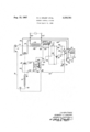
'The single figure of the drawing is a diagrammatic il'lustration of a burner control system for a conventional, pressure-type, oil burner;
Referring to the drawing, the primary elements of the system include an oil burner having a driving motor 12, a space thermostat 14, a motor relay having a winding 16 and two sets of normally open contacts 18 and 22, a normally closed thermal time switch 24 (safety switch) including an electrical resistance heater 26, a photoconductive element 28, a silicon-controlled rectifier 30 (SCR) having a gate lead 31 and 'a gate control network comprising the photoconductive element '28, an adjustable resistor 32 with sliding contact 34 and a fixed resistor 36, a capacitor 38, a normally closed scavenging time switch 42 including 'an' electrical resistance heater 44, a spark igniter comprising "electrodes 52 and a voltage step-up transformer 54, a voltage step-down, power source transformer having a primary winding 56 and a secondary winding 58, and a pair of power supply leads 60 and 62 for connecting transformer primary winding 56 across a suitable source of A.C. electrical power.
The oil burner 10 includes the usual blower and fuel pump, which are driven by motor 12 to supply atomized 3,335,781 Patented Aug. 15, 1967 ICC oil and combustion air to the burner where the mixture is ignited by arcing across igniter electrodes 52. The burner motor 12 and the primary winding of the igniter transformer 54 are connected in parallel across the power supply leads 60 and 62 through relay contacts 22, when closed, by leads 64, 66, 68, 70, and 72. The motor 12 and igniter 52-54 are therefore energized simultaneously upon closure of normally open relay contacts 22.
The motor relay winding is connected across the power transformer secondary winding 58 through a circuit which may be traced from the left side to the right side of winding 58 as follows: a lead 74, space thermostat 14, a lead 76, a lead 78, winding 16, leads 80 and 86, scavenger switch 42, leads 88 and 90, resistance vheater 26, a lead 92, SCR30, leads 94 and 96, safety switch 24, and lead 98 to the right side of winding 58.
Upon closure of -re'lay contacts 18, a .shunt around scavenging switch 42 is completed. Starting at unction 100 this shunt includes lead 102, contacts 18, and a lead 40.
A second shunt around the scavenging switch 42, the safety switch heater 26, and the SCR is also completed upon closure of relay contacts 18. Starting at junction 46, this shunt includes lead 48, the scavenging switch heater 44, and the lead 50 to lead 96 at junction 20.
The photoconductive element 28 is of the semicon- I ductor type which has extremely high electrical resistance in the absence of the light of burner flame and becomes considerably less resistive to the passage of electrical current when it sees burner ame. The positioning of photoconductive element 28 so as to be responsive to the presence of burner ame and yet be shielded from ambient light is preferably that shown and described in United States letters Patent No. 3,079,982, issued Mar. 15, 1953, to Bernardus I. Sta-ring.
The fixed resistor 36 and the photoconductive element 28 are connected in parallel between the SCR gate lead 31 and the cathode side of SCR30, and the adjustable resistor 32 is connected between the gate lead 31 and the anode side of SCRS() at a point 112. The relative values of fixed resistor 36 and vadjustable resistor 32, as adjusted, is such that a firing signal is applied to the SCR gate early in each conductive ha'lf cycle of the SCR under conditions in which the thermostat is closed and no flame exists at the burner 10. The resistance of photoconductive element 28 under no-iiame condition is very high so that the voltage drop is determined by the relative values of resistors 32 and 36 which causes the SCR30 to fire. When flame appears at the burner 10, the resistance of photoconductive element 28 decreases considerably, and as a result, a
reduced voltage drop occurs thereacross which reduces provides protection for the SCR by absorbing any transient high voltage pulses which may occur due to switching at thermostat 14 which may otherwise cause damage vto SCR30. The va'lue of capacitor 38 is such that the current passed thereby is small and would not appreciably laffect the lheat output of safety switch heater 26, or develop any appreciable electromagnetic force in winding 16.
period of time by resistance heater 26 opens and, upon opening, is latched open by a spring latch 114. Reclosure' of'safety switch 24 requires manual unlatching. Scavenging switch 42 includes a bimetal switch arm which when heated for la predetermined period of time by resistance heater 44 opens and recloses in a predetermined period of time when resistance heater 44 is de-energized.
3 OPERATION Under normal operating conditions the closure of thermostat 14, upon demand for heat, connects the relay winding 16 across power source transformer secondary winding 58 through scavenging switch 42, safety switch resistance heater 26, SCR30, and safety switch 24. The relay winding 16 is also connected across the power source secondary 58 through scavenging switch heater 44 and leads 48 and 50. There being no flame at the burner at this time, the resistance of photoconductive element 28 is very lhigh and SCRS() is therefore conductive, providing half cycle conduction which, in addition to the full wave current flowing through the shunt formed by lead 48, scavenging switch 44, and lead 50, effects sufiicient energization of winding 16 to cause the closing of relay contacts 18 and 22. The closing of relay contacts 22 completes the circuit across power supply leads 60-62, thereby energizing burner motor 12 and igniter 54 whereupon a combustible mixture is supplied to burner and ignited.
The closing of contacts 18 simultaneously completes the described shunt around scavenging switch 42, comprising lead 102, contacts 18, and lead 40, so that even though switch 42 opens the safety switch heater 26 remains energized through this shunt. The opening time of scavenging switch 42 is thereby rendered non-critical.
When combustion fiame appears, conduction through SCR30 is cut ofi, and the safety switch heater 26 becomes de-energized. Suliicient energization of relay 16 to hold contacts 18 and 22 closed is now provided through the shunt comprising lead 48, scavenging switch heater 44, and lead 50. The resistance of scavenging switch heater 44 is such, however, as to limit the current passing through winding 16 to that which will hold the contacts 18 and 22 closed once they are closed, but is insufiicient to effect an energization of winding 16 which will effect the closing of contacts 18 and 22 from an open position. After a short, predetermined period of time the scavenging switch heater 44 causes the bimetal contact arm of scavenging switch 42 to warp open and remain open. Under normal conditions the burner will now continue to operate until thermostat 14 opens. When the thermostat opens the relay contacts 18 and 22 open, cutting off the fuel supply and extinguishing burner flame. Thereafter the scavenger switch arm 42 cools and closes in a predetermined time. Re-starting is therefore ldelayed for a predetermined scavenging period.
If, for any reason, ignition of the combustible mixture at the burner fails to occur within a predetermined short period of time following the closing of thermostat 14, conduction through SCR30` will cause safety switch heater 26 to effect the warping open of safety switch 24, which will then remain latched open. Opening of safety switch 24 de-energizes the entire system.
If the photoconductive element 28 becomes conductive in the absence of burner flame, for any reason, during inoperation of the burner, SCR30 will be non-conductive and the relay 16 will not be energized sufficiently upon closure of thermostat 14 through leads 48, scavenging switch heater 44, and lead 50 to effect the closing of contacts 18 and 22. If the element 28 becomes inoperative during burner operation so as to become conductive in the absence of burner flame, operation of the burner will be terminated in a normal manner by the opening of thermostat 14 when sufficient heat has been supplied and re-starting will be prevented. Also, if the element 28 fails to respond to burner ame to become conductive, SCR30 will remain conductive and effect the opening of safety switch 24 in a predetermined short period of time.
If SCR30 malfunctions so as to continue to remain conductive for any reason after flame appears at the burner 10, the safety switch 24 will open after a short predetermined peri-od of time.
If the electrical power source fails after burner operation has been established and the scavenging switch 42 has opened, sufficient re-energization of relay winding 16 to reclose the contacts 18 and 22 will be delayed for a predetermined scavenging period during which the bimetal switch arm of scavenging switch 42 is cooling sufficiently to reclose.
The foregoing description is intended to be illustrative and not limiting, the scope of the invention being set forth in the appended claims.
We claim:
1. In a burner control system, a burner, an A.C. power source, a normally open relay operative when closed to cause fuel to be supplied to said burner and to cause the operation of ignition means to ignite it, a winding for said relay which when fully energized effects the closing of said relay, circuit means connecting said relay winding across said power source to effect under certain conditions a simultaneous full wave and half wave energization thereof sufficient to close said relay and under other conditions to effect only the full wave energization thereof sufficient to hold said relay closed once it is closed, but insufiicient to cause it to close, said circuit means including circuit connections connecting a space thermostat, said relay winding, a safety switch resistance heater which when half wave energized for a predetermined short interval effects the opening of a normally closed safety switch, a silicon controlled rectifier, and the normally closed safety switch across said power source in series arrangement and in the order recited, and circuit connections connecting a current limiting resistor in parallel with said safety switch heater and said silicon controlled rectifier, a fiame responsive control network for said rectifier including a gate lead, a photoconductive element and first and second resistors, circuit connections connecting said photocondutive element and said first resistor in parallel between said gate lead and the cathode side of said rectifier, and circuit connections connecting said second resistor between said gate lead and the anode side of said rectifier, said photoconductive element being responsive to burner flame and having considerably higher electrical resistance in the absence of flame than when fiame exists, and the electrical resistance of said first and second resistors and of said photoconductive element in the absence of fiame being such as to effect conduction of said rectifier, and the decrease in resistance of said photoconductive element in response to fiame being such as to reduce the signal applied to said gate lead below that required to effect conduction.
2. A burner control system as set forth in claim 1 which further includes a normally closed scavenging switch connected in series between said relay winding and said safety switch resistance heater, and in which said current limiting resistor is a resistance heater operative when energized for a predetermined period of time to effect the opening of said scavenging switch.
3. A burner control system as set forth in claim 2 which further includes circuit connections completed upon the closure of said relay shunting said scavenging switch.
References Cited UNITED STATES PATENTS 3,174,528 3/1965 Staring 158--28 3,276,507 10/1966 Eldridge et a1 158-28 JAMES W. WESTHAVER, Primary Examiner.
Claims (1)
1. IN A BURNER CONTROL SYSTEM, A BURNER, AN A.C. POWER SOURCE, A NORMALLY OPEN RELAY OPERATIVE WHEN CLOSED TO CAUSE FUEL TO BE SUPPLIED TO SAID BURNER AND TO CAUSE THE OPERATION OF IGNITION MEANS TO IGNITE IT, A WINDING FOR SAID RELAY WHICH WHEN FULLY ENERGIZED EFFECTS THE CLOSING OF SAID RELAY, CIRCUIT MEANS CONNECTING SAID RELAY WINDING ACROSS SAID POWER SOURCE TO EFFECT UNDER CERTAIN CONDITIONS A SIMULTANEOUS FULL WAVE AND HALF WAVE ENERGIZATION THEREOF SUFFICIENT TO CLOSE SAID RELAY AND UNDER OTHER CONDITIONS TO EFFECT ONLY THE FULL WAVE ENERGIZATION THEREOF SUFFICIENT TO HOLD SAID RELAY CLOSED ONCE IT IS CLOSED, BUT INSUFFICIENT TO CAUSE IT TO CLOSE, SAID CIRCUIT MEANS INCLUDING CIRCUIT CONNECTIONS CONNECTING A SPACE THERMOSTAT, SAID RELAY WINDING, A SAFETY SWITCH RESISTANCE HEATER WHICH WHEN HALF WAVE ENERGIZED FOR A PREDETERMINED SHORT INTERVAL EFFECTS THE OPENING OF A NORMALLY CLOSED SAFETY SWITCH, A SILICON CONTROLLED RECTIFIER, AND THE NORMALLY CLOSED SAFETY SWITCH ACROSS SAID POWER SOURCE IN SERIES ARRANGEMENT AND IN THE ORDER RECITED, AND CIRCUIT CONNECTIONS CONNECTING A CURRENT LIMITING RESISTOR IN PARALLEL WITH SAID SAFETY SWITCH HEATER AND SAID SILICON CONTROLLED RECTIFIER, A FLAME RESPONSIVE CONTROL NETWORK FOR SAID RECTIFIER INCLUDING A GATE LEAD, A PHOTOCONDUCTIVE ELEMENT AND FIRST AND SECOND RESISTORS, CIRCUIT CONNECTIONS CONNECTING SAID PHOTOCONDUCTIVE ELEMENT AND SAID FIRST RESISTOR IN PARALLEL
Priority Applications (1)
| Application Number | Priority Date | Filing Date | Title |
|---|---|---|---|
| US541657A US3335781A (en) | 1966-04-11 | 1966-04-11 | Burner control system |
Applications Claiming Priority (1)
| Application Number | Priority Date | Filing Date | Title |
|---|---|---|---|
| US541657A US3335781A (en) | 1966-04-11 | 1966-04-11 | Burner control system |
Publications (1)
| Publication Number | Publication Date |
|---|---|
| US3335781A true US3335781A (en) | 1967-08-15 |
Family
ID=24160520
Family Applications (1)
| Application Number | Title | Priority Date | Filing Date |
|---|---|---|---|
| US541657A Expired - Lifetime US3335781A (en) | 1966-04-11 | 1966-04-11 | Burner control system |
Country Status (1)
| Country | Link |
|---|---|
| US (1) | US3335781A (en) |
Cited By (2)
| Publication number | Priority date | Publication date | Assignee | Title |
|---|---|---|---|---|
| US3393966A (en) * | 1966-11-23 | 1968-07-23 | Koehring Co | Burner control |
| US4257759A (en) * | 1979-03-15 | 1981-03-24 | Honeywell Inc. | Fuel burner primary control means |
Citations (2)
| Publication number | Priority date | Publication date | Assignee | Title |
|---|---|---|---|---|
| US3174528A (en) * | 1965-03-23 | Staring burner control system | ||
| US3276507A (en) * | 1965-02-01 | 1966-10-04 | Emerson Electric Co | Burner control system |
-
1966
- 1966-04-11 US US541657A patent/US3335781A/en not_active Expired - Lifetime
Patent Citations (2)
| Publication number | Priority date | Publication date | Assignee | Title |
|---|---|---|---|---|
| US3174528A (en) * | 1965-03-23 | Staring burner control system | ||
| US3276507A (en) * | 1965-02-01 | 1966-10-04 | Emerson Electric Co | Burner control system |
Cited By (2)
| Publication number | Priority date | Publication date | Assignee | Title |
|---|---|---|---|---|
| US3393966A (en) * | 1966-11-23 | 1968-07-23 | Koehring Co | Burner control |
| US4257759A (en) * | 1979-03-15 | 1981-03-24 | Honeywell Inc. | Fuel burner primary control means |
Similar Documents
| Publication | Publication Date | Title |
|---|---|---|
| US2269157A (en) | Automatic fluid fuel burner control | |
| US3941553A (en) | Heater safety control system | |
| US2159658A (en) | Control system | |
| US4073611A (en) | Control system for gas burning apparatus | |
| US3318358A (en) | Burner igniter system | |
| US3488131A (en) | Electronic spark ignitor control for fuel burner | |
| US3393039A (en) | Burner control system | |
| US2086823A (en) | Control system for fuel burners | |
| US3174528A (en) | Staring burner control system | |
| US3276507A (en) | Burner control system | |
| GB1415041A (en) | Safety control circuit for fuel burning apparatus | |
| US3335781A (en) | Burner control system | |
| US2230732A (en) | Control for oil burners | |
| US3060997A (en) | Oil burner and control system therefor | |
| US4167389A (en) | Oil burner primary control for interrupted ignition system | |
| US3672811A (en) | Burner control system using a radiation operated relay means | |
| US3059693A (en) | Control system | |
| US2398008A (en) | Burner control mechanism | |
| US3554680A (en) | Burner control system | |
| US4406612A (en) | Oil burner primary control for interrupted ignition system | |
| US3153440A (en) | Electric igniting and fuel supply control arrangement for fuel burners | |
| US3446565A (en) | Ignition system | |
| US3204685A (en) | Burner ignition and control system | |
| US3671169A (en) | Delayed fuel and post ignition timed burner control system | |
| US3767354A (en) | Oil burner control system |