US3335761A - Weft guiding apparatus - Google Patents
Weft guiding apparatus Download PDFInfo
- Publication number
- US3335761A US3335761A US484363A US48436365A US3335761A US 3335761 A US3335761 A US 3335761A US 484363 A US484363 A US 484363A US 48436365 A US48436365 A US 48436365A US 3335761 A US3335761 A US 3335761A
- Authority
- US
- United States
- Prior art keywords
- thread
- weft
- weft thread
- slay
- shuttle
- Prior art date
- Legal status (The legal status is an assumption and is not a legal conclusion. Google has not performed a legal analysis and makes no representation as to the accuracy of the status listed.)
- Expired - Lifetime
Links
Images
Classifications
-
- D—TEXTILES; PAPER
- D03—WEAVING
- D03D—WOVEN FABRICS; METHODS OF WEAVING; LOOMS
- D03D47/00—Looms in which bulk supply of weft does not pass through shed, e.g. shuttleless looms, gripper shuttle looms, dummy shuttle looms
Definitions
- the present invention relates to a weft guiding apparatus, and more particularly to apparatus for guiding a weft thread drawn from a weft supply during a pick in such a manner that the weft thread does not slide on the fell of the web which is being woven.
- a weft inserting means in the form of a gripper shuttle or needle holds the weft thread during the pick so that the weft thread is drawn from a stationary weft supply.
- the weft supply is a thread package located outside of the warp shed and laterally of the slay on the stationary frame of the loom.
- a thread guide means is used for feeding the weft thread from the thread supply to the weft inserting means, for example to the gripper shuttle so that the same grips the weft thread and pulls it off the weft supply during the pick, while the weft thread slides through the eye of the thread guide.
- the thread guide may be mounted on the machine frame or on the slay, and performs the function of placing the weft thread in a position in which it can be gripped by the shuttle while the same is located outside of the warp shed If the thread guide is arranged on the slay, the weft thread can be attached to the gripper shuttle in any posi tion of the slay, however, this operation is usually carried out during the rearward motion of the slay from its front dead center position to the rear dead center position.
- the disadvantage of this construction is thatthe thread guide increases the inertia of the slay, which is undesirable, particularly if a weft changing device for supplying weft threads of different colors has to be mounted on the slay.
- the reciprocating movement of the slay must be controlled in such a manner that the same remains in the rear dead center position for a certain time necessary for the insertion of the weft thread into the gripper shuttle, or other weft inserting means.
- apparatus of this type has the disadvantage that the thread guide means is located forwardly of the fell of the woven Web while placing the weft thread in the gripper shuttle, which is due to the fact that the gripper shuttle is located forwardly of the fell of the web when the slay is in its front position in which the reed beats the last Weft thread into the web. Consequently, when the gripper shuttle moves rearwardly with the slay during the pick, lines passing through the gripper shuttle and the thread guide cross the fell of the web, so that the weft thread is drawn by the shuttle over the selvedge warp threads in the region of the fell of the web.
- weft thread If there is any irregularity in the weft thread, it may tear or break, and particularly if synthetic fibers such as nylon are used as weft thread, substantial heat develops due to the friction, resulting in scorching of the threads.
- Another object of the invention is to place weft guide means for a weft thread during the pick in such a position that a weft thread guided by the thread guide does not frictionally engage the threads of the woven web.
- Another object of the invention is to hold a thread guide in .a forward position while the same inserts a weft thread into a gripper shuttle, and to hold the thread guide in a rearward position while the shuttle draws a weft thread through the thread guide during the pick.
- Another object of the invention is to prevent abrasion of a weft thread during its insertion into a warp shed.
- Another object is to obtain a faster movement of a picked gripper shuttle drawing a weft thread from a weft supply by guiding the drawn off weft thread along a path spaced from the fell and the selvedge of the woven web so that frictional engagement between the Weft thread and the web is prevented.
- the present invention relates to a weft guiding apparatus which is provided in a loom having a slay reciprocable between front and rear dead center positions, and weft inserting means, such as a gripper. shuttle or needle, mounted for movement across the slay between two end positions located outward of the warp shed of the web.
- weft inserting means is in one of the end positions thereof when the slay is in the front dead center position.
- One embodiment of the invention comprises thread supply means for supplying a weft thread, for example a thread package supported on the frame of the loom; thread guide means, preferably having an eye for guiding the weft thread, and having a first position located for- Wardly ofthe fell of the web for feeding and attaching the weft thread to the weft inserting means, or more particularly to the gripper of a gripper shuttle while the same is in one of said end positions and the slay is in the front,
- the drive means control the thread guide means in such a manner that the weft thread is attached to the gripper shuttle while the slay is in the front position, while in the second position of the thread guide means, a plane through the eye of the thread guide and the gripper shuttle in any position during the pick, does not cross the fell of the fabric.
- the drawn thread is not bent at the selvedge of the web in the region of the fell of the web, passes through the warp shed without frictional engagement with the web, and is not subject to abrasion.
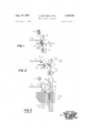
- FIG. 1 is a fragmentary side elevation illustrating an embodiment of the invention in a first operational position in which the slay is in its front position and a weft thread is fed to a gripper shuttle;
- FIG. 2 is a side elevation corresponding to FIG. 1 but illustrating the apparatus in another operational position during the insertion of a weft thread into a warp shed;
- FIG. 3 is a fragmentary schematic plan View illustrating apparatus according to the prior art in the operational position of FIG. 2;
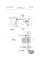
- FIG. 4 is a side elevation corresponding to FIG. 2 and illustrating the drive means for reciprocating the thread guide means
- FIG. 5 is a fragmentary plan view illustrating the apparatus of the invention in the operational position of FIG. 4 during the insertion of a weft thread into a warp shed.
- a slay 9 is angularly reciprocated in the usual manner between a front dead center position shown in FIG. 1, and a rear dead center position toward which the slay moves in the direction of the arrow S in FIG. 2.
- the slay carries a reed 8 with reed elements passing between adjacent warp threads, so that during forward movement of the reed 8 from the position of FIG. 2 to the position of FIG. 1, the last picked weft 11 is beaten into the fell of the web 21 which is being woven.
- the weft inserting means shown to be a gripper shuttle 10
- picking means 22 When the weft inserting means, shown to be a gripper shuttle 10, is picked by picking means 22 while located in a shuttle box 23, it moves from one end position on one side of the warp shed through the same to the other side of the warp shed, two positions of the gripper shuttle being shown in FIGS. 3 and 4.
- Picking means 22 and shuttle boxes 23 are mounted on the slay for reciprocating movement with the same, and are provided on both sides of the slay.
- the gripper shuttle 10 in a shuttle box 23 is located in the region of the eye 2 of a weft guide 1 as shown in FIG. 1.
- a weft thread 3 supplied from a cross wound package 5 on the stationary frame of the loom passes through eye 2 into the web 21 where it is located as the weft thread 12 which was inserted before the last weft thread 11.
- the last weft thread 11 was picked from the other side of the loom and was supplied by another weft thread package 5 located on the other side of the loom and passing through a thread guide 1, not shown, on the other side of the loom.
- FIG. 3 corresponds to the prior art, and it will be appreciated that considerable friction will develop between the weft thread 3 sliding on the threads of the web and more particularly at the juncture of the last weft thread 11 and the outermost warp threads in a bent and kinked position.
- thread guide 1 is moved after insertion of the weft thread 3 into the gripper of the shuttle 10 from its first position shown in FIG. 1 to a second position shown in FIG. 5 in which the eye 2 of the thread guide 1 is located rearwardly of the last weft thread 11 and of the fell of the newly woven web. Consequently, when the shuttle is picked and travels in the direction S the weft thread portion 3a does not engage the fell of the fabric, or the selvedge of the web and is located along a straight line connecting eye 2 with the gripper of shuttle 10.
- the weft thread portion 3a is also located in a plane passing through the gripper of the shuttle, eye 2 and thread supply package 5, and the eye 2 is advantageously slanted, as shown in FIG. 5, to guide the weft thread 3 which is drawn off the supply package 5 without substantially bending the Weft thread.
- Eye 2 may also taper toward shuttle 10 as shown in FIG. 5.
- a cam 31 is driven by a shaft 32 which rotates at half the number of revolutions of the main shaft of the loom.
- Cam 31 is engaged by a cam follower roller 33 on a lever 19 which is turnable about a pivot 20 and is urged by a spring 24 toward cam 31 so that lever 19 is reciprocated.
- Lever 19 has at its free end a slot 18 receiving a pin 17 on thread guide 1 which is guided in a guide sleeve 16 for rectilinear movement.
- slay 9 with reed 8 move first rearward to the rear dead center position and then forward to the front dead center position to beat the last inserted weft into the fell of the fabric.
- the last weft thread 11 was just beaten by reed 8 after having been drawn from a thread supply means 5 on the other side of the loom, not shown, by gripper shuttle 10 moving in a direction opposite to the direction of the arrow S
- Shuttle 10 has grippers at opposite ends, so that a weft thread 3 from supply means 5 can be gripped by the free gripper of the shuttle when the same arrives in the region of the eye 2 of thread guide 1 in the position of FIG. 1. Since thread 3 passing through eye 2 is still connected with the weft thread 12 in the web, cutting mean 30 cuts off thread 3 after insertion into shuttle 10, so that the shuttle can be picked for movement in the direction of the arrow S as shown in FIG. 5.
- thread supply means for supplying weft thread
- thread guide means located between the weft thread supply means and the edge of the web and having a weft thread guide portion which guides said weft thread
- said thread guide means having a first position in which said guide portion is located forwardly of the fell and in position for attaching the weft thread to said weft inserting means located in the associated one of said end positions while said slay means is in said front dead center position
- drive means operating in timed relationship with said slay means for moving said thread guide means rearward to a second position in which said guide portion is located rearwardly of the fell so that during insertion into a shed the weft thread passing from said supply means through said guide portion to said weft inserting means is delivered rearward of and out of contact with said fell.
- said drive means includes a driven rotary cam, wherein said reciprocating member is a cam follower cooperating with said cam and being reciprocated by the same during rotation thereof, and means connecting said thread guide means with said cam follower so that said thread guide means is reciprocated between said first and second positions.
- said thread guide means is an elongated needle having said guide portion at one end thereof, said guide portion having a bore extending through said needle slanted to the longitudinal direction of the same so as to be substantially located in a plane extending between said thread supply means and the path of said weft inserting means.
Landscapes
- Engineering & Computer Science (AREA)
- Textile Engineering (AREA)
- Looms (AREA)
Description
Aug. 15, 1967 v, BARTOSEK ETAL' I 3,
' WEIIFT-GUIDING APPARATUS Filed Sept; *1, 19615 I 2 Sheets-Sheet l FIG. 3
ATTORNEY 2 Sheets$heei 2 FiledSept.
M'M' BY 00 I ATTOR EY 3,335,761 WEFT GUIDING APPARATUS Vladimir Bartosek, Vilem Janousek, and Otto Rotrekl,
Brno, Czechoslovakia, assignors to Elitex Sdruzeni Podniku Textilniho Strojirenstvi, Liherec, Czechoslovakia Filed Sept. 1, 1965, Ser. No. 484,363 Claims priority, application Czechoslovakia, Sept. 2, 1964, 4,892/64 8 Claims. (Cl. 139-125) The present invention relates to a weft guiding apparatus, and more particularly to apparatus for guiding a weft thread drawn from a weft supply during a pick in such a manner that the weft thread does not slide on the fell of the web which is being woven.
Looms are well known in which a weft inserting means in the form of a gripper shuttle or needle holds the weft thread during the pick so that the weft thread is drawn from a stationary weft supply. The weft supply is a thread package located outside of the warp shed and laterally of the slay on the stationary frame of the loom. A thread guide means is used for feeding the weft thread from the thread supply to the weft inserting means, for example to the gripper shuttle so that the same grips the weft thread and pulls it off the weft supply during the pick, while the weft thread slides through the eye of the thread guide.
The thread guide may be mounted on the machine frame or on the slay, and performs the function of placing the weft thread in a position in which it can be gripped by the shuttle while the same is located outside of the warp shed If the thread guide is arranged on the slay, the weft thread can be attached to the gripper shuttle in any posi tion of the slay, however, this operation is usually carried out during the rearward motion of the slay from its front dead center position to the rear dead center position. The disadvantage of this construction is thatthe thread guide increases the inertia of the slay, which is undesirable, particularly if a weft changing device for supplying weft threads of different colors has to be mounted on the slay.
When the thread guide means is mounted on the frame of the loom in such a position as to feed the weft thread to the gripper shuttle in the rear dead center position of the slay, the reciprocating movement of the slay must be controlled in such a manner that the same remains in the rear dead center position for a certain time necessary for the insertion of the weft thread into the gripper shuttle, or other weft inserting means.
Since this operation is carried out in the rear dead center position of the slay in which the gripper shuttle has passed to the other side of the warp shed, the weft thread is inserted into the shuttle at the far side of the warp shed after a pick. This arrangement has the disadvantage that the slay has to be delayed for a considerable time in its rear position, and such time is frequently more than one-half of the time required for an operational cycle. Another disadvantage is that it can be checked only after a pick whether the weft thread was properly inserted into the gripper shuttle. The delay in the rear position of the slay requires a faster movement of the slay toward and away from the front position in which the weft thread is beaten by the reed, so that a web of lesser density is obtained.
In order to overcome these disadvantages, it has been proposed to feed the weft thread into the weft inserting means, for example into a gripper shuttle, while the slay is in the front dead center position so that the weft inserting means can be picked during the movement of the slay from the front position to the rear position. In such an arrangement, the reciprocating motion of the slay is United States Patent 3,335,761 Patented Aug. 15, 1967 continuous without any time delay in the front or rear position so that a fabric of the same quality is obtained as is produced in standard looms in which the shuttle carries a weft thread supply.
However, apparatus of this type according to the prior art has the disadvantage that the thread guide means is located forwardly of the fell of the woven Web while placing the weft thread in the gripper shuttle, which is due to the fact that the gripper shuttle is located forwardly of the fell of the web when the slay is in its front position in which the reed beats the last Weft thread into the web. Consequently, when the gripper shuttle moves rearwardly with the slay during the pick, lines passing through the gripper shuttle and the thread guide cross the fell of the web, so that the weft thread is drawn by the shuttle over the selvedge warp threads in the region of the fell of the web. Since the drawn or pulled weft thread is bent at the selvedge of the web and slides along the same, the selvedge warp threads, the last beaten weft thread, and the weft thread drawn by the shuttle frictionally engage on each other and are abraded, while the speed of the shuttle pulling the weft thread is reduced.
If there is any irregularity in the weft thread, it may tear or break, and particularly if synthetic fibers such as nylon are used as weft thread, substantial heat develops due to the friction, resulting in scorching of the threads.
It is one object of the invention to overcome the dis advantages of known weft guiding apparatus for feeding a weft thread into a weft inserting means, such as a gripper shuttle or needle, and to provide a weft guiding apparatus in which a new weft thread is freely drawn from a supply package by the weft inserting means without frictionally engaging the woven web.
Another object of the invention is to place weft guide means for a weft thread during the pick in such a position that a weft thread guided by the thread guide does not frictionally engage the threads of the woven web.
Another object of the invention is to hold a thread guide in .a forward position while the same inserts a weft thread into a gripper shuttle, and to hold the thread guide in a rearward position while the shuttle draws a weft thread through the thread guide during the pick.
Another object of the invention is to prevent abrasion of a weft thread during its insertion into a warp shed.
Another object is to obtain a faster movement of a picked gripper shuttle drawing a weft thread from a weft supply by guiding the drawn off weft thread along a path spaced from the fell and the selvedge of the woven web so that frictional engagement between the Weft thread and the web is prevented.
With these objects in view, the present invention relates to a weft guiding apparatus which is provided in a loom having a slay reciprocable between front and rear dead center positions, and weft inserting means, such as a gripper. shuttle or needle, mounted for movement across the slay between two end positions located outward of the warp shed of the web. In the loom with which the present invention is concerned, the weft inserting means is in one of the end positions thereof when the slay is in the front dead center position.
One embodiment of the invention comprises thread supply means for supplying a weft thread, for example a thread package supported on the frame of the loom; thread guide means, preferably having an eye for guiding the weft thread, and having a first position located for- Wardly ofthe fell of the web for feeding and attaching the weft thread to the weft inserting means, or more particularly to the gripper of a gripper shuttle while the same is in one of said end positions and the slay is in the front,
dead center position, and a second position located rearward of the fell of the web; and drive means for operating, or more particularly reciprocating the thread guide means in timed relationship with the slay.
The drive means control the thread guide means in such a manner that the weft thread is attached to the gripper shuttle while the slay is in the front position, while in the second position of the thread guide means, a plane through the eye of the thread guide and the gripper shuttle in any position during the pick, does not cross the fell of the fabric. As a result, the drawn thread is not bent at the selvedge of the web in the region of the fell of the web, passes through the warp shed without frictional engagement with the web, and is not subject to abrasion.
The novel features which are considered as characteristic for the invention are set forth in particular in the appended claims. The invention itself, however, both as to its construction and its method of operation, together with additional objects and advantages thereof, will be best understood from the following description of specific embodiments when read in connection with the accompanying drawings, in which:
FIG. 1 is a fragmentary side elevation illustrating an embodiment of the invention in a first operational position in which the slay is in its front position and a weft thread is fed to a gripper shuttle;
FIG. 2 is a side elevation corresponding to FIG. 1 but illustrating the apparatus in another operational position during the insertion of a weft thread into a warp shed;
FIG. 3 is a fragmentary schematic plan View illustrating apparatus according to the prior art in the operational position of FIG. 2;
FIG. 4 is a side elevation corresponding to FIG. 2 and illustrating the drive means for reciprocating the thread guide means; and
FIG. 5 is a fragmentary plan view illustrating the apparatus of the invention in the operational position of FIG. 4 during the insertion of a weft thread into a warp shed.
Referring now to the drawing, conventional well known parts of the loom, which is provided with a thread guiding apparatus of the invention, are not shown, or only schematically illustrated. A slay 9 is angularly reciprocated in the usual manner between a front dead center position shown in FIG. 1, and a rear dead center position toward which the slay moves in the direction of the arrow S in FIG. 2. The slay carries a reed 8 with reed elements passing between adjacent warp threads, so that during forward movement of the reed 8 from the position of FIG. 2 to the position of FIG. 1, the last picked weft 11 is beaten into the fell of the web 21 which is being woven. When the weft inserting means, shown to be a gripper shuttle 10, is picked by picking means 22 while located in a shuttle box 23, it moves from one end position on one side of the warp shed through the same to the other side of the warp shed, two positions of the gripper shuttle being shown in FIGS. 3 and 4. Picking means 22 and shuttle boxes 23 are mounted on the slay for reciprocating movement with the same, and are provided on both sides of the slay.
When the slay is in its front position shown in FIG. 1, the gripper shuttle 10 in a shuttle box 23 is located in the region of the eye 2 of a weft guide 1 as shown in FIG. 1. A weft thread 3 supplied from a cross wound package 5 on the stationary frame of the loom, passes through eye 2 into the web 21 where it is located as the weft thread 12 which was inserted before the last weft thread 11. The last weft thread 11 was picked from the other side of the loom and was supplied by another weft thread package 5 located on the other side of the loom and passing through a thread guide 1, not shown, on the other side of the loom.
When the slay in its front position shown in FIG. 1 places the shuttle 10 in the region of the eye of the thread guide 1, the weft thread 3 is fed to the shuttle and inserted into the gripper of the same. Thereupon, cutting means 30 cut the weft thread between the shuttle and the previously inserted weft thread 12 in the vicinity of the web edge so that the shuttle can be picked through a shed 7 formed in the usual manner by heddle frames of alternating warp thread 6, 6. In the position of FIG. 1, the reed 8 beats the last weft thread 11 into the fell of the fabric, and the speed of the slay is at a minimum. At this moment shuttle 10 is located outside of the warp in a shuttle box 23 and is thereupon picked while the slay 9 with the reed 8 move in the direction S toward the rear dead center position.
At the beginning of the pick, the portion of weft thread 3 between the eye 2 and the gripper of shuttle 10 does not cross the last weft thread 11, and is located in the warp shed. However, as shuttle 10 continues its movement to the position shown in broken lines in FIG. 3 and in FIG. 5, a plane passing through eye 2 of thread guide 1 and the gripper of the shuttle, will cross the last weft thread 11 and the fell of the fabric so that the weft thread is bent in the region of the selvedge at the point D, and frictionally engages the woven web during the further travel of the shuttle which is due to the fact that the thread guide 1, 2 is located a distance B forwardly of the last weft thread 11, the distance corresponding to four weft threads 11, 12, 13 and 14 forming with the warp threads the last woven part of the web.
The position shown in FIG. 3 corresponds to the prior art, and it will be appreciated that considerable friction will develop between the weft thread 3 sliding on the threads of the web and more particularly at the juncture of the last weft thread 11 and the outermost warp threads in a bent and kinked position.
In accordance with the present invention, thread guide 1 is moved after insertion of the weft thread 3 into the gripper of the shuttle 10 from its first position shown in FIG. 1 to a second position shown in FIG. 5 in which the eye 2 of the thread guide 1 is located rearwardly of the last weft thread 11 and of the fell of the newly woven web. Consequently, when the shuttle is picked and travels in the direction S the weft thread portion 3a does not engage the fell of the fabric, or the selvedge of the web and is located along a straight line connecting eye 2 with the gripper of shuttle 10. At the beginning of the movement, the weft thread portion 3a is also located in a plane passing through the gripper of the shuttle, eye 2 and thread supply package 5, and the eye 2 is advantageously slanted, as shown in FIG. 5, to guide the weft thread 3 which is drawn off the supply package 5 without substantially bending the Weft thread. Eye 2 may also taper toward shuttle 10 as shown in FIG. 5.
The rearward movement of thread guide 1, from the position shown in broken lines in FIG. 4 to the position shown in solid lines in FIGS. 4 and 5, is obtained by drive means illustrated in FIG. 4. A cam 31 is driven by a shaft 32 which rotates at half the number of revolutions of the main shaft of the loom. Cam 31 is engaged by a cam follower roller 33 on a lever 19 which is turnable about a pivot 20 and is urged by a spring 24 toward cam 31 so that lever 19 is reciprocated. Lever 19 has at its free end a slot 18 receiving a pin 17 on thread guide 1 which is guided in a guide sleeve 16 for rectilinear movement.
Since shaft 32 rotates at half the speed as the main shaft of the loom by which the slay is reciprocated, a thread guide 1 is advanced from the position of FIG. 1 on either side of the loom after each second beating motion of the slay 9 with reed 8 toward the front position shown in FIG. 1. Alternate operation of the thread guides 1 on opposite sides of the loom is required since the picks are carried out alternately from opposite sides of the loom.
During the picking of a weft, slay 9 with reed 8 move first rearward to the rear dead center position and then forward to the front dead center position to beat the last inserted weft into the fell of the fabric. In the position of FIG. 1, the last weft thread 11 was just beaten by reed 8 after having been drawn from a thread supply means 5 on the other side of the loom, not shown, by gripper shuttle 10 moving in a direction opposite to the direction of the arrow S Shuttle 10 has grippers at opposite ends, so that a weft thread 3 from supply means 5 can be gripped by the free gripper of the shuttle when the same arrives in the region of the eye 2 of thread guide 1 in the position of FIG. 1. Since thread 3 passing through eye 2 is still connected with the weft thread 12 in the web, cutting mean 30 cuts off thread 3 after insertion into shuttle 10, so that the shuttle can be picked for movement in the direction of the arrow S as shown in FIG. 5.
It will be understood that each of the elements described above, or two or more together, may also find a useful application in other types of looms differing from the types described above.
While the inventionhas been illustrated and described as embodied in a Weft guiding apparatus including a thread guide movable to a position for preventing frictional engagement between a Weft thread inserted into a warp shed, and the already woven web, it is not intended to be limited to the details shown, since various modifications and structural changes may be made without departing in any way from the spirit of the present invention.
Without further analysis, the foregoing will so fully reveal the gist of the present invention that others can by applying current knowledge readily adapt it for various applications without omitting features that, from the standpoint of prior art, fairly constitute essential characteristics of the generic or specific aspects of this invention and, therefore, such adaptations should and are intended to be comprehended within the meaning and range of equivalence of the following claims.
What is claimed as new and desired to be secured b Letters Patent is: i
1. In combination with a loom having slay means reciprocable between front and rear dead center positions, and weft inserting means mounted for movement through warp sheds along a path between two end positions located laterally outward of the web being woven: thread supply means for supplying weft thread; thread guide means located between the weft thread supply means and the edge of the web and having a weft thread guide portion which guides said weft thread, said thread guide means having a first position in which said guide portion is located forwardly of the fell and in position for attaching the weft thread to said weft inserting means located in the associated one of said end positions while said slay means is in said front dead center position; and drive means operating in timed relationship with said slay means for moving said thread guide means rearward to a second position in which said guide portion is located rearwardly of the fell so that during insertion into a shed the weft thread passing from said supply means through said guide portion to said weft inserting means is delivered rearward of and out of contact with said fell.
2. The apparatus defined in claim 1 wherein said guide portion of said thread guide means is an eye.
3. An apparatus as defined in claim 1 wherein said drive means include a reciprocating member connected with said thread guide means for moving the same forward from said second position to said first position when said slay means arrives at said rear dead center position.
4. An apparatus as defined in claim 3 wherein said drive means includes a driven rotary cam, wherein said reciprocating member is a cam follower cooperating with said cam and being reciprocated by the same during rotation thereof, and means connecting said thread guide means with said cam follower so that said thread guide means is reciprocated between said first and second positions.
5. An apparatus as defined in claim 1 wherein said weft inserting means is a gripper shuttle.
6. An apparatus as defined in claim 1 wherein said thread guide means is an elongated needle having said guide portion at one end thereof, said guide portion having a bore extending through said needle slanted to the longitudinal direction of the same so as to be substantially located in a plane extending between said thread supply means and the path of said weft inserting means.
7. An apparatus as defined in claim 6 wherein said bore in said guide portion tapers toward said web.
8. An apparatus as defined in claim 1 wherein said guide portion when in said second position of said thread guide means is rearward of said front dead center position of said slay means.
References Cited UNITED STATES PATENTS 3,092,150 6/1963 Birmans et al. 139-122 3,163,184 12/1964 Cherpin 139-125 3,237,656 3/1966 Haupt 139-122 MERVIN STEIN, Primary Examiner. HENRY S JAUDON, Examiner,
Claims (1)
1. IN COMBINATION WITH A LOOM HAVING SLAY MEANS RECIPROCABLE BETWEEN FRONT AND REAR DEAD CENTER POSITIONS, AND WEFT INSERTING MEANS MOUNTED FOR MOVEMENT THROUGH WARP SHEDS ALONG A PATH BETWEEN TWO END POSITIONS LOCATED LATERALLY OUTWARD OF THE WEB BEING WOVEN: THREAD SUPPLY MEANS FOR SUPPLYING WEFT THREAD; THREAD GUIDE MEANS LOCATED BETWEEN THE WEFT THREAD SUPPLY MEANS AND THE EDGE OF THE WEB AND HAVING A WEFT THREAD GUIDE PORTION WHICH GUIDES SAID WEFT THREAD, SAID THREAD GUIDE MEANS HAVING A FIRST POSITION IN WHICH SAID GUIDE PORTION IS LOCATED FORWARDLY OF THE FELL AND IN POSITION FOR ATTACHING THE WEFT THREAD TO SAID WEFT INSERTING MEANS LOCATED IN THE ASSOCIATED ONE OF SAID END POSITIONS WHILE SAID SLAY MEANS IS IN SAID FRONT DEAD CENTER POSITION; AND DRIVE MEANS OPERATING IN TIMED RELATIONSHIP WITH SAID SLAY MEANS FOR MOVING SAID THREAD GUIDE MEANS REARWARD TO A SECOND POSITION IN WHICH SAID GUIDE PORTION IS LOCATED REARWARDLY OF THE FELL SO THAT DURING INSERTION INTO A SHED THE WEFT THREAD PASSING FROM SAID SUPPLY MEANS THROUGH SAID GUIDE PORTION TO SAID WEFT INSERTING MEANS IS DELIVERED REARWARD OF AND OUT OF CONTACT WITH SAID FELL.
Applications Claiming Priority (1)
| Application Number | Priority Date | Filing Date | Title |
|---|---|---|---|
| CS489264 | 1964-09-02 |
Publications (1)
| Publication Number | Publication Date |
|---|---|
| US3335761A true US3335761A (en) | 1967-08-15 |
Family
ID=5392667
Family Applications (1)
| Application Number | Title | Priority Date | Filing Date |
|---|---|---|---|
| US484363A Expired - Lifetime US3335761A (en) | 1964-09-02 | 1965-09-01 | Weft guiding apparatus |
Country Status (7)
| Country | Link |
|---|---|
| US (1) | US3335761A (en) |
| AT (1) | AT258229B (en) |
| BE (1) | BE668621A (en) |
| CH (1) | CH435142A (en) |
| DE (1) | DE1535400A1 (en) |
| GB (1) | GB1084392A (en) |
| SE (1) | SE301774B (en) |
Cited By (2)
| Publication number | Priority date | Publication date | Assignee | Title |
|---|---|---|---|---|
| US4875507A (en) * | 1986-12-30 | 1989-10-24 | N.V. Michel Van De Wiele | Process and apparatus for guiding the weft threads in weaving looms |
| WO2018041127A1 (en) * | 2016-08-30 | 2018-03-08 | 江苏友诚数控科技有限公司 | Moving-reed weft cutting mechanism of air jet loom |
Citations (3)
| Publication number | Priority date | Publication date | Assignee | Title |
|---|---|---|---|---|
| US3092150A (en) * | 1959-06-02 | 1963-06-04 | Dewas Raymond | Weaving method and loom |
| US3163184A (en) * | 1961-02-10 | 1964-12-29 | Cherpin Jean Victor | Gripper shuttle |
| US3237656A (en) * | 1962-06-26 | 1966-03-01 | Dewas Raymond | Weaving loom comprising a device for the guiding and supervision of the weft thread |
-
1965
- 1965-01-22 AT AT54165A patent/AT258229B/en active
- 1965-07-09 SE SE9109/65A patent/SE301774B/xx unknown
- 1965-07-14 DE DE19651535400 patent/DE1535400A1/en active Pending
- 1965-07-21 CH CH1022065A patent/CH435142A/en unknown
- 1965-07-28 GB GB32219/65A patent/GB1084392A/en not_active Expired
- 1965-08-20 BE BE668621D patent/BE668621A/xx unknown
- 1965-09-01 US US484363A patent/US3335761A/en not_active Expired - Lifetime
Patent Citations (3)
| Publication number | Priority date | Publication date | Assignee | Title |
|---|---|---|---|---|
| US3092150A (en) * | 1959-06-02 | 1963-06-04 | Dewas Raymond | Weaving method and loom |
| US3163184A (en) * | 1961-02-10 | 1964-12-29 | Cherpin Jean Victor | Gripper shuttle |
| US3237656A (en) * | 1962-06-26 | 1966-03-01 | Dewas Raymond | Weaving loom comprising a device for the guiding and supervision of the weft thread |
Cited By (2)
| Publication number | Priority date | Publication date | Assignee | Title |
|---|---|---|---|---|
| US4875507A (en) * | 1986-12-30 | 1989-10-24 | N.V. Michel Van De Wiele | Process and apparatus for guiding the weft threads in weaving looms |
| WO2018041127A1 (en) * | 2016-08-30 | 2018-03-08 | 江苏友诚数控科技有限公司 | Moving-reed weft cutting mechanism of air jet loom |
Also Published As
| Publication number | Publication date |
|---|---|
| CH435142A (en) | 1967-04-30 |
| GB1084392A (en) | 1967-09-20 |
| BE668621A (en) | 1965-12-06 |
| DE1535400A1 (en) | 1970-09-24 |
| SE301774B (en) | 1968-06-17 |
| AT258229B (en) | 1967-11-10 |
Similar Documents
| Publication | Publication Date | Title |
|---|---|---|
| US3638686A (en) | Carriers for filling insertion in a weaving machine | |
| US3952778A (en) | Selvage forming device | |
| US3621885A (en) | Filling cutting device for a weaving machine | |
| US4078586A (en) | Method and apparatus for producing a selvage | |
| US4006758A (en) | Narrow web loom | |
| US3335761A (en) | Weft guiding apparatus | |
| US3111966A (en) | Method and apparatus for simultaneously weaving lengths of fabric | |
| US3565121A (en) | Weft selecting and presenting apparatus | |
| US3426807A (en) | Loom | |
| US3460583A (en) | Edge forming device for looms | |
| US2561416A (en) | Selvage forming mechanism | |
| US3443602A (en) | Device and method for producing a selvedge | |
| US2816576A (en) | Looms for weaving | |
| US3554240A (en) | Feeding device of filling yarn used for shuttleless loom | |
| US3592241A (en) | Weft thread control apparatus | |
| US3347283A (en) | Weft control apparatus | |
| US4126159A (en) | Apparatus and method for stabilizing rapiers | |
| US4655263A (en) | Apparatus for presenting weft threads to the clamps of gripper rods in shuttleless looms | |
| US1825110A (en) | Pile fabric loom | |
| US3431951A (en) | Loom filling positioner | |
| US2990854A (en) | Selvage forming on fabrics | |
| US3989069A (en) | Method of and apparatus for compensating for weft tension in traveling-wave shedding looms | |
| US3678967A (en) | Shedding motion for a weaving machine | |
| US3960186A (en) | Weft yarn control device | |
| US3298400A (en) | Filling carrier for shuttleless looms |