US3335687A - Apparatus for a hydrofoil provided with air exit apertures - Google Patents
Apparatus for a hydrofoil provided with air exit apertures Download PDFInfo
- Publication number
- US3335687A US3335687A US517212A US51721265A US3335687A US 3335687 A US3335687 A US 3335687A US 517212 A US517212 A US 517212A US 51721265 A US51721265 A US 51721265A US 3335687 A US3335687 A US 3335687A
- Authority
- US
- United States
- Prior art keywords
- valve
- foil
- air
- hydrofoil
- pressure
- Prior art date
- Legal status (The legal status is an assumption and is not a legal conclusion. Google has not performed a legal analysis and makes no representation as to the accuracy of the status listed.)
- Expired - Lifetime
Links
- 239000011888 foil Substances 0.000 description 79
- 230000033001 locomotion Effects 0.000 description 15
- XLYOFNOQVPJJNP-UHFFFAOYSA-N water Substances O XLYOFNOQVPJJNP-UHFFFAOYSA-N 0.000 description 8
- 238000010276 construction Methods 0.000 description 4
- 230000009467 reduction Effects 0.000 description 4
- 230000001105 regulatory effect Effects 0.000 description 4
- 230000009471 action Effects 0.000 description 3
- 230000008859 change Effects 0.000 description 3
- 230000007423 decrease Effects 0.000 description 2
- 230000001419 dependent effect Effects 0.000 description 2
- 238000005192 partition Methods 0.000 description 2
- 230000033228 biological regulation Effects 0.000 description 1
- 230000006835 compression Effects 0.000 description 1
- 238000007906 compression Methods 0.000 description 1
- 230000001276 controlling effect Effects 0.000 description 1
- 230000003247 decreasing effect Effects 0.000 description 1
- 238000006073 displacement reaction Methods 0.000 description 1
- 230000000694 effects Effects 0.000 description 1
- 230000003628 erosive effect Effects 0.000 description 1
- 238000007654 immersion Methods 0.000 description 1
- 239000000463 material Substances 0.000 description 1
- 238000000926 separation method Methods 0.000 description 1
Images

Classifications
-
- B—PERFORMING OPERATIONS; TRANSPORTING
- B63—SHIPS OR OTHER WATERBORNE VESSELS; RELATED EQUIPMENT
- B63B—SHIPS OR OTHER WATERBORNE VESSELS; EQUIPMENT FOR SHIPPING
- B63B1/00—Hydrodynamic or hydrostatic features of hulls or of hydrofoils
- B63B1/16—Hydrodynamic or hydrostatic features of hulls or of hydrofoils deriving additional lift from hydrodynamic forces
- B63B1/24—Hydrodynamic or hydrostatic features of hulls or of hydrofoils deriving additional lift from hydrodynamic forces of hydrofoil type
- B63B1/28—Hydrodynamic or hydrostatic features of hulls or of hydrofoils deriving additional lift from hydrodynamic forces of hydrofoil type with movable hydrofoils
- B63B1/285—Hydrodynamic or hydrostatic features of hulls or of hydrofoils deriving additional lift from hydrodynamic forces of hydrofoil type with movable hydrofoils changing the angle of attack or the lift of the foil
- B63B1/288—Hydrodynamic or hydrostatic features of hulls or of hydrofoils deriving additional lift from hydrodynamic forces of hydrofoil type with movable hydrofoils changing the angle of attack or the lift of the foil using gas exhaust through the foil
-
- B—PERFORMING OPERATIONS; TRANSPORTING
- B64—AIRCRAFT; AVIATION; COSMONAUTICS
- B64C—AEROPLANES; HELICOPTERS
- B64C23/00—Influencing air flow over aircraft surfaces, not otherwise provided for
- B64C23/005—Influencing air flow over aircraft surfaces, not otherwise provided for by other means not covered by groups B64C23/02 - B64C23/08, e.g. by electric charges, magnetic panels, piezoelectric elements, static charges or ultrasounds
Definitions
- a hydrofoil having air exit apertures arranged at the underpressure region of the hydrofoil and at least one controllable valve means for delivering air to such air exit apertures.
- means are provided which are responsive to changes in pressure and cooperate with the valve means in a manner that upon appearance of pressure changes such valve means is actuated at least in certain pressure ranges.
- the present invention relates to an apparatus for hydrofoils which are provided with air exit openings or apertures at the underpressure or low-pressure region of the foil to which air is delivered through the agency of at least one controllable valve.
- a known apparatus of this type where the hydrofoil operates in the region of cavitation exhibits valves by means of which there is regulated the delivery of air to the upper side of the foil for influencing cavitation, and thus lift, for the purpose of maneuvering and which can by manually controlled (Italian Patent No. 549,266- Grattarola).
- this known apparatus due to the underpressure prevailing during movement at the suction side (underpressure or low-pressure side) of the foil, air is sucked from the atmosphere which then streams out of the air exit apertures at the upper side of the foil and thereby reduces cavitation.
- a further, more specific object of this invention is particularly directed to the provision of an apparatus by means of which it is possible to reduce, or even completely suppress, the fluctuations in lift, which occur through change of the angle of attack in the orbital motion of the water or with changes in velocity of the watercraft.
- the inventive apparatus it is possible to considerably improve the behavior of the foil and the watercraft carried thereby in the waves or motion of the water and/ or during changes in speed.
- By appropriate construction of the apparatus it is also possible to suppress the increase of lift which occurs with increase of the velocity of the foil with respect to the water and which previously resulted in a reduction of the immersion depth with partially submerged foils and, thus, also in a reduction in stability.
- the apparatus is applicable for use in conjunction with partially submerged as well as fully submerged foils.
- the suction side of the foil is delivered with air as soon as the angle of attack increases due to the orbital motion of the waves, whereby the increase in lift is completely or partially suppressed.
- the pressure side of the foil is supplied with air as soon as the angle of attack becomes smaller, whereby the reduction in lift is completely or partially stopped. It is also possible to implement the physical structure of inventive apparatus such that control of delivery of air takes place to both sides of the foil.
- the inventive apparatus can be constructed such that an increasing air quantity automatically discharges at the upper side of the foil when the velocity of the watercraft increases relative to the water, whereby the lift of the foil can be maintained practically constant.
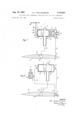
- FIGURE 1 schematically illustrates a first embodiment of control device with an air admission valve for influencing the suction side of the foil wherein this foil is depicted in cross-section;
- FIGURE 2 schematically illustrates a further embodiment of the control device with an air admission valve for influencing the pressure side of the foil and once again, such foil is shown in cross-section;
- FIGURE 3 schematically illustrates a third embodiment of control device having an air admission valve for influencing both the suction side and the pressure side of the foil with the latter shown in cross-section;
- FIGURE 4 schematically illustrates a fourth embodiment of control device incorporating air admission valve for influencing the suction side of the foil shown in crosssection
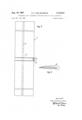
- I V FIGURE 5 is a plan view of a hydrofoil for the purpose of illustrating the arrangement of the air exit apertures and suction apertures at the hydrofoil;
- FIGURE 6 is a sectional view of the foil depicted in FIGURE 5.
- reference character 1 designates the air admission valve
- reference character 8 denotes the hydrofoil.
- the air admission valve 1 is normally located above the surface of the water at the non-illustrated boat or watercraft and is provided with an air inlet or intake conduit 3, the free end of which opens into the atmosphere or can also be operably connected with a non-illustrated air container or reservoir.
- a foil chamber or compartment 15 Internally of the hydrofoil 8 there is located a foil chamber or compartment 15 which, as shown in FIGURE 5, advantageously extends over the full spread of the foil 8 transverse to the lengthwise direction of the watercraft and is provided throughout substantially its entire length with air exit apertures or openings 16 leading to the upper surface of this foil 8.
- Foil 8 is secured by means of non-illustrated brackets or supports to the hull of the watercraft, in a manner well known to those versed in the art.
- the inner compartment of the air admission valve 1 is connected in the region of its central portion with the chamber 15 of the foil 8 by means of an air inlet duct or conduit 14.
- the slide 4 of the air admission valve 1 carrying the pistons 4' and 4" is displaceably or slidably arranged for movement along the lengthwise axis of the cylindrical valve housing 2.
- the forward piston 4 serves as a valve element for controlling the admission of air via the air intake 3 and connecting duct 14 to the foil chamber 15, whereas the second piston 4" serves as a pressure equalization piston.
- the left side of this piston 4 is subjected to the external pressure admitted via the opening 2a at the valve housing 2.
- This piston 4" also serves to eliminate axial forces which would appear when, with opened air delivery, an underpressure or lowpressure occurs between the pistons 4 and 4" in the air admission valve 1.
- a closing spring 5 in the form of a spiral or helical spring is housed in the forward valve compartment 21.
- the left end of this closing spring 5 bears against the piston 4' of the slide 4 while its right end bears against a valve disk or plate 12.
- Closing spring 5 is normally biased or prestressed in such a manner that it keeps the valve 1 closed and against the action of the atmospheric pressure which operates from the left against the piston 4", as such is best depicted in FIGURE 1.
- the valve disk 12 which is secured against rotation is provided with an internal threading with which engages a rotatable spindle 11.
- the latter is arranged axially in the valve housing 2 and is secured against axial displacement.
- gear 13 which, in the embodiment of FIGURE 1, is at the right of the drawing.
- Gear 13 can be operated from the pilot -or control area of the watercraft through the agency of any suitable expedients, such as non-illustrated known connection elements, for example a chain or a flexible shaft having a pinion secured to its end. In this manner it is possible to regulate within predetermined limits the prestress of the spring 5 and, thus, the point of opening of the valve 1 and thereby the quantity of air delivered to the foil chamber 15.
- the forward valve chamber or compartment 21 is connected via a control conduit 6 with a control chamber or compartment 7 arranged in the neighborhood of the forward edge of the foil 8 and within the body of such foil.
- This control chamber 7, as best recognized by referring to FIGURE 5, extends over a relatively small portion of the spread of the foil 8 and transverse to the watercraft. It will also be seen that suction channels 9 lead from the control chamber 7 to the upper side of the hydrofoil 8 in the region of its forward edge towards the outside.
- the entire apparatus previously described functions in the following manner:
- the closing spring 5 is dimensioned and adjusted such that with normal movement of the watercraft it holds the air admission valve 1 closed. It is compressed by the external pressure acting from the left upon the piston 4" as soon as an appreciable underpressure appears in the control compartment 7 and thus also in the forward valve compartment 21, which is the case during increase of the angle of attack or the relative velocity of the foil 8 to the water.
- admission of air to the foil chamber 15, via the air inlet 3 and connecting duct 14 is rendered possible at a predetermined underpressure which is dependent upon the adjustment of the aforementioned spring.
- the degree to which the air admission valve 1 is opened is dependent upon the magnitude of the underpressure prevailing in the valve compartment 21.
- a rocking or tilt lever 23 is mounted for pivotable movement at a pivot bolt 26 secured to the housing 2 of the valve 1.
- One end 23' of this rocking or tilt lever 23 is connected with an actuating member 24 leading to the pilots compartment, for instance a traction cable.
- the other end 23" of such operating or tilt lever 23 is coupled with an axial extension 25 of the slide 4, so that upon pulling the cable 24, the tilt lever 23 is rocked in counterclockwise direction, thereby pressing the slide 4 towards the right and freeing the delivery of air from the air inlet or conduit 3 to the connecting duct 14.
- This manner of actuating the air admission valve 1 can be employed for the purpose of braking the watercraft. When this is done, the lift of the foil 8 is considerably reduced, so that the body or hull of the boat immerses and thereby the resistance is considerably increased.
- valve unit possessing the construction depicted in FIGURE 1, it is possible as will be developed hereinafter, to also regulate the delivery of air to the underside of the foil. Moreover, by using two such valves, it is possible to regulate the delivery of air both to the upper side as well as to the underside of the foil.
- the chamber or compartment 15 of such foil 8 is connected with air exit apertures or channels 16' which communicate at the bottom or underside of said foil with the outside.
- the control chamber or compartment 7' arranged at the region of the forward edge of the foil 8, is operably connected with downwardly directed suction apertures or channels 9' which communicate with the outside or surroundings at the region of such forward edge.
- a control conduit or duct 6 leads from the control chamber 7' into the forward valve chamber or compartment 21 of the air admission valve 1.
- valve chamber 22 In contrast to FIGURE 1, in the apparatus of FIGURE 2., there is not provided any spring for closing the valve 1, rather the closing force of the valve, in this case, is provided by generating an underpressure at the left or rear valve chamber 22.
- This valve chamber 22 is, for this purpose, connected with an additional chamber 7" by means of a duct or conduit 10.
- Chamber 7 similar to the previously considered chamber or compartment 7', is arranged at the region of the forward edge of the foil 8 and is provided with a suction channel or a number of suction channels 9" which lead to the outside at the upper surface or side of the foil and in the region of the forward edge thereof.
- the closing force is too large in the embodiment depicted in FIGURE 2, so that the valve 1 will not be opened as soon as such is desired.
- a needle valve 17 the valve element 17 of which is adjustable. With the aid of this needle valve it is possible via the connecting conduit to introduce additional air from the atmosphere into the conduit 10, whereby the pressure in the rear valve compartment increases, and thus opening of the valve 1" is assisted.
- the opening and closing movements of the needle valve 17 are preferably controlled from the pilots compartment of the watercraft in any suitable well known manner.
- the opening movement or path of the slide 4 is proportional to the pressure difference between the pressures at the suction openings at the upper side and the underside of the foil, that is, proportional to the negative angle of attack. Since the pressures in both valve compartments 21 and 22 change as a function of the square of the velocity of the watercraft or the oncoming flow, the once regulated pressure relationship is maintained for each velocity. Thus, the valve of FIGURE 2 only responds to changes in the angle of attack due to orbital motion in the waves, however, not to changes in velocity of the watercraft.
- FIGURE 3 depicts a variant embodiment of apparatus which has been modified with respect to that of FIG- URE 2 in two respects.
- this embodiment there is carried out regulation of the delivery of air both to the suction side as well as to the pressure side of the foil, and secondly, there is only employed a specially designed single valve 1 in which two pistons 4' and 4 possessing different cross-sections are arranged at the slide 4 of the valve 1.
- the piston 4 of which controls the admission of air to the upper side of the foil is connected via the conduit or duct 6' with the suction channels 9 at the upper side
- the piston 4" of which controls the delivery of air to the foil underside is connected via the conduit or duct 6" with the suction channels 9 at the underside.
- the piston 4 for the foil upper side possesses a smaller diameter in accordance with the larger underpressure prevailing at this location, than the diameter of the piston 4 for the foil underside.
- Pressure springs 5' and 5" which act upon the pistons 4' and 4", respectively, ensure that the opening path of the slide 4 is proportional to the angle of attack.
- valve of FIGURE 3 which only responds to the orbital motion of the water, in principle is the same as the valve of FIGURE 2. If the angle of attack increases, then the underpressure increases at the right valve chamber 21, whereas it decreases in the left chamber 22, so that the slide 4 travelling towards the right admits air to the upper side of the foil. A decrease of the angle of attack brings about the opposite operation: air is delivered to the underside of the foil. In both cases, the admission or delivery of air balances changes in lift.
- FIGURE 4 A further embodiment of valve which possesses a corresponding manner of operation to that of the valve of FIGURE 1, is shown in FIGURE 4.
- a valve disk 18 is provided internally of the chamber 15 of the foil 8.
- the piston 4a of the slide 4 in the valve cylinder 2 which is subjected to underpressure via the conduit 6 for the purpose of attaining the opening force, is connected by a valve rod 19 with the valve disk 18.
- the air delivery conduit 3 to the upper side of the valve disk 18, in the usual situation wherein the foil 8 is connected to the hull of the boat by means of hollow supports or brackets, is formed by the hollow compartment of a bracket and an opening communicating with the atmosphere provided at the upper portion of the bracket. Atmospheric pressure acts against the upper face of the piston 4a via the opening 2a of the valve housing 2.
- valve body which controls the throughpassage opening for the air can be of any desired type.
- the piston 4a of the embodiment of FIGURE 4 can be replaced by a bellows or a piston with roll diaphragm.
- FIGURE 5 there is illustrated the arrangement of the control chamber 7 with the suction channels or openings 9 at the hydrofoil 8. While it is preferable to have the air exit apertures 16 or 16' extending rearwardly of the foil 8, in the manner shown in the previous embodiments, it would also be possible to have them located above the associated foil chamber 15, as shown in FIGURE 5. If the control valve 1 is opened due to the increase of the underpressure at the foil, the inflowing air again reduces this pressure change over the entire foil depth, so that the suction force through the openings of the suction channels 9 again drops, which brings about a return movement of the valve.
- the openings of the suction channel 9, as depicted in FIGURE 5, are arranged at a section of the foil between two profile sections in which there do not open any air exit apertures 16.
- a partition or separation member 20 extending in the direction of travel (see also FIGURE 6) which reduces pressure equalization between the aerated outer foil portions and the suction openings 9.
- At least one controllable valve means for delivering air to said air exit apertures, means responsive to changes in pressure provided at the underpressure region of the hydrofoil cooperating with said valve means such that upon the appearance of pressure changes said valve means is actuated at least in certain pressure ranges.
- valve means includes a slide which is actuated at least in certain pressure ranges upon the appearance of pressure changes.
- valve means incorporates means for applying atmospheric pressure to said slide at a side opposite the side against which said closing force is effective, so that opening of said valve means is carried out under the action of the atmospheric pressure working against said closing force, said conduit means communicating the underpressure existing in said chamber to said opposite side of said slide.
- said means subjecting said slide to a closing force comprises spring means, and means for regulating the bias of said spring means capable of being actuated from the pilots area of the watercraft with which the hydrofoil is to be used.
- said controllable valve means is a slide valve comprising a valve housing closed at both ends, a pair of pistons operably interconnected with one another arranged for sliding movement within said valve housing, one of said pistons being movable in a direction towards its associated end of said valve housing for freeing the passage of air to said air exit apertures leading to the upper side of said hydrofoil, the other of said pistons being movable in a direction towards its associated end of said valve housing for freeing the passage of air to said air exit apertures leading to the underside of said hydrofoil, said means responsive to changes in pressure incorporating suction opening means located at the upper side of said hydrofoil and suction opening means located at the underside of said hydrofoil, said one piston communicating with said suction opening means located at said upper side and said other piston communicating with said suction opening means located at said underside.
- said means responsive to changes in pressure incorporate at least one chamber located internally of said hydrofoil and at least one opening communicating with said chamber, said last-mentioned opening being located at a portion of said hydrofoil devoid of air exit a ertures, partition means extending in the direction of travel of said hydrofoil located to both sides of said at least one opening for separating the portion of the hydrofoil provided with said at least one opening from the remaining portions of said hydrofoil.
Description
' 1967 H. F. VON SCHERTEL' 3,335,687-
APPARATUS FOR A HYDROFOIL PROVIDED WITH AIR EXIT APERTURES 1 Filed Dec. 29, 1965 JSSheets-Shset 1 DS- 115, 1967 H. F \ION SCI-YIERTEZL 3,335,687
APIARKTUS FOR A HYDROFOIL PROVIDED WITH AIR EXIT APERTURES j Filed Dec. 29, 1965 asheets-sheet Y oco o ooooooo INVENTOR:
United States Patent 3,335,687 APPARATUS FUR A HYDROFOIL PROVIDED WHTH AIR EXIT APERTURES Hans Freiherr von Schertel, Hergiswil am See, Switzerland, assignor to Supramar A.G., Lucerne, Switzeriand Fiied Dec. 29, 1965, Ser. No. 517,212 Claims. (Cl. 114-66.5)
ABSTRACT OF THE DISCLOSURE A hydrofoil having air exit apertures arranged at the underpressure region of the hydrofoil and at least one controllable valve means for delivering air to such air exit apertures. According to the invention, means are provided which are responsive to changes in pressure and cooperate with the valve means in a manner that upon appearance of pressure changes such valve means is actuated at least in certain pressure ranges.
The present invention relates to an apparatus for hydrofoils which are provided with air exit openings or apertures at the underpressure or low-pressure region of the foil to which air is delivered through the agency of at least one controllable valve.
A known apparatus of this type where the hydrofoil operates in the region of cavitation exhibits valves by means of which there is regulated the delivery of air to the upper side of the foil for influencing cavitation, and thus lift, for the purpose of maneuvering and which can by manually controlled (Italian Patent No. 549,266- Grattarola). In this known apparatus, due to the underpressure prevailing during movement at the suction side (underpressure or low-pressure side) of the foil, air is sucked from the atmosphere which then streams out of the air exit apertures at the upper side of the foil and thereby reduces cavitation. However, in certain cases there is also provided for the infeed of pressurized air to the air exit apertures.
Up to the present, no apparatuses have become known to the art which automatically counteract at such hydrofoils the lift fluctuations periodically occurring in the motion of the water, the cavitation or the increase of lift dur' ing increase of velocity due to the admixing of air in the flow stream.
Accordingly, it is a primary object of this invention to provide an improved apparatus by means of which it is possible to effectively solve the aforementioned problem.
A further, more specific object of this invention is particularly directed to the provision of an apparatus by means of which it is possible to reduce, or even completely suppress, the fluctuations in lift, which occur through change of the angle of attack in the orbital motion of the water or with changes in velocity of the watercraft.
Owing to the inventive apparatus, it is possible to considerably improve the behavior of the foil and the watercraft carried thereby in the waves or motion of the water and/ or during changes in speed. By appropriate construction of the apparatus, it is also possible to suppress the increase of lift which occurs with increase of the velocity of the foil with respect to the water and which previously resulted in a reduction of the immersion depth with partially submerged foils and, thus, also in a reduction in stability.
By appropriate construction it is possible, by means of the new and improved apparatus, to reduce the lift of the foil by regulating the quantity of air flowing to it from the atmosphere in non-linear relationship to such.
The apparatus is applicable for use in conjunction with partially submerged as well as fully submerged foils.
3,335,687 Patented Aug. 15, 1967 According to the invention, with an apparatus of the previously mentioned type, there are additionally arranged at the underpressure region of the foil, elements which re spond to pressure changes and which are operably connected with the valve or its slide in such, a manner that, with the appearance of changes in pressure, the slide is actuated at least in certain pressure ranges.
Due to this apparatus, according to one embodiment, it is possible to deliver air to the suction side of the foil as soon as the angle of attack increases due to the orbital motion of the waves, whereby the increase in lift is completely or partially suppressed. According to another physical embodiment, the pressure side of the foil is supplied with air as soon as the angle of attack becomes smaller, whereby the reduction in lift is completely or partially stopped. It is also possible to implement the physical structure of inventive apparatus such that control of delivery of air takes place to both sides of the foil.
Experimentation has shown that also cavitation which changingly occurs in the waves or swell at uncontrolled foils of faster watercraft can be prevented by the introduced or delivered air quantity insofar as such is maintained sufficiently large, so that the known consequences of cavitation can be prevented. These are not only the increased resistance and the erosion of the material of the foil, but rather also the dangerous effects of cavitation at the pressure side of the foil with negative angle of attack which leads to pronounced downward pressure forces which allow the watercraft to strike the waves hard.
According to a further embodiment, the inventive apparatus can be constructed such that an increasing air quantity automatically discharges at the upper side of the foil when the velocity of the watercraft increases relative to the water, whereby the lift of the foil can be maintained practically constant.
Other features, objects and advantages of the invention Will become apparent by reference to the following detailed description and drawings, wherein like reference characters have been generally used throughout the various embodiments for the same or analogous elements and, for the sake of clarity in illustration, the air admission control valve is depicted in considerably enlarged scale with respect to the foil, and wherein:
FIGURE 1 schematically illustrates a first embodiment of control device with an air admission valve for influencing the suction side of the foil wherein this foil is depicted in cross-section;
, FIGURE 2 schematically illustrates a further embodiment of the control device with an air admission valve for influencing the pressure side of the foil and once again, such foil is shown in cross-section;
FIGURE 3 schematically illustrates a third embodiment of control device having an air admission valve for influencing both the suction side and the pressure side of the foil with the latter shown in cross-section;
FIGURE 4 schematically illustrates a fourth embodiment of control device incorporating air admission valve for influencing the suction side of the foil shown in crosssection; I V FIGURE 5 is a plan view of a hydrofoil for the purpose of illustrating the arrangement of the air exit apertures and suction apertures at the hydrofoil; and
FIGURE 6 is a sectional view of the foil depicted in FIGURE 5.
Describing now the drawings, it will be recognized that in the exemplary embodiment of FIGURE 1, reference character 1 designates the air admission valve, whereas reference character 8 denotes the hydrofoil. The air admission valve 1 is normally located above the surface of the water at the non-illustrated boat or watercraft and is provided with an air inlet or intake conduit 3, the free end of which opens into the atmosphere or can also be operably connected with a non-illustrated air container or reservoir. Internally of the hydrofoil 8 there is located a foil chamber or compartment 15 which, as shown in FIGURE 5, advantageously extends over the full spread of the foil 8 transverse to the lengthwise direction of the watercraft and is provided throughout substantially its entire length with air exit apertures or openings 16 leading to the upper surface of this foil 8. Foil 8 is secured by means of non-illustrated brackets or supports to the hull of the watercraft, in a manner well known to those versed in the art.
The inner compartment of the air admission valve 1 is connected in the region of its central portion with the chamber 15 of the foil 8 by means of an air inlet duct or conduit 14. The slide 4 of the air admission valve 1 carrying the pistons 4' and 4" is displaceably or slidably arranged for movement along the lengthwise axis of the cylindrical valve housing 2. The forward piston 4 serves as a valve element for controlling the admission of air via the air intake 3 and connecting duct 14 to the foil chamber 15, whereas the second piston 4" serves as a pressure equalization piston. The left side of this piston 4 is subjected to the external pressure admitted via the opening 2a at the valve housing 2. This piston 4" also serves to eliminate axial forces which would appear when, with opened air delivery, an underpressure or lowpressure occurs between the pistons 4 and 4" in the air admission valve 1.
A closing spring 5 in the form of a spiral or helical spring is housed in the forward valve compartment 21. The left end of this closing spring 5 bears against the piston 4' of the slide 4 while its right end bears against a valve disk or plate 12. Closing spring 5 is normally biased or prestressed in such a manner that it keeps the valve 1 closed and against the action of the atmospheric pressure which operates from the left against the piston 4", as such is best depicted in FIGURE 1.
The valve disk 12 which is secured against rotation is provided with an internal threading with which engages a rotatable spindle 11. The latter is arranged axially in the valve housing 2 and is secured against axial displacement. Thus, it is possible to displace the valve disk 12 by appropriately rotating this spindle 11. For the purpose of operating spindle 11 there is mounted at its free end a gear 13 which, in the embodiment of FIGURE 1, is at the right of the drawing. Gear 13 can be operated from the pilot -or control area of the watercraft through the agency of any suitable expedients, such as non-illustrated known connection elements, for example a chain or a flexible shaft having a pinion secured to its end. In this manner it is possible to regulate within predetermined limits the prestress of the spring 5 and, thus, the point of opening of the valve 1 and thereby the quantity of air delivered to the foil chamber 15.
The forward valve chamber or compartment 21 is connected via a control conduit 6 with a control chamber or compartment 7 arranged in the neighborhood of the forward edge of the foil 8 and within the body of such foil. This control chamber 7, as best recognized by referring to FIGURE 5, extends over a relatively small portion of the spread of the foil 8 and transverse to the watercraft. It will also be seen that suction channels 9 lead from the control chamber 7 to the upper side of the hydrofoil 8 in the region of its forward edge towards the outside.
The entire apparatus previously described functions in the following manner: The closing spring 5 is dimensioned and adjusted such that with normal movement of the watercraft it holds the air admission valve 1 closed. It is compressed by the external pressure acting from the left upon the piston 4" as soon as an appreciable underpressure appears in the control compartment 7 and thus also in the forward valve compartment 21, which is the case during increase of the angle of attack or the relative velocity of the foil 8 to the water. Upon compression of the closing spring 5, admission of air to the foil chamber 15, via the air inlet 3 and connecting duct 14, is rendered possible at a predetermined underpressure which is dependent upon the adjustment of the aforementioned spring. As should be readily apparent, the degree to which the air admission valve 1 is opened is dependent upon the magnitude of the underpressure prevailing in the valve compartment 21. By appropriate dimensioning of the elements of the apparatus, it is possible by virtue of the action of the air quantity flowing to the foil compartment 15 and escaping from the air exit apertures or channels 16 to maintain the lift approximately constant during increase of the angle of attack and/ or the velocity of the watercraft.
In order to be able to arbitrarily or freely open the air admission valve 1 from the pilots compartment or control area of the watercraft, a rocking or tilt lever 23 is mounted for pivotable movement at a pivot bolt 26 secured to the housing 2 of the valve 1. One end 23' of this rocking or tilt lever 23 is connected with an actuating member 24 leading to the pilots compartment, for instance a traction cable. The other end 23" of such operating or tilt lever 23 is coupled with an axial extension 25 of the slide 4, so that upon pulling the cable 24, the tilt lever 23 is rocked in counterclockwise direction, thereby pressing the slide 4 towards the right and freeing the delivery of air from the air inlet or conduit 3 to the connecting duct 14. This manner of actuating the air admission valve 1 can be employed for the purpose of braking the watercraft. When this is done, the lift of the foil 8 is considerably reduced, so that the body or hull of the boat immerses and thereby the resistance is considerably increased.
By means of a valve unit possessing the construction depicted in FIGURE 1, it is possible as will be developed hereinafter, to also regulate the delivery of air to the underside of the foil. Moreover, by using two such valves, it is possible to regulate the delivery of air both to the upper side as well as to the underside of the foil.
In the embodiment of apparatus depicted in FIGURE 2, for the purpose of influencing the pressure at the underside of the foil 8, the chamber or compartment 15 of such foil 8 is connected with air exit apertures or channels 16' which communicate at the bottom or underside of said foil with the outside. Accordingly, the control chamber or compartment 7', arranged at the region of the forward edge of the foil 8, is operably connected with downwardly directed suction apertures or channels 9' which communicate with the outside or surroundings at the region of such forward edge. Similar to the embodiment of FIGURE 1 previously considered, here also a control conduit or duct 6 leads from the control chamber 7' into the forward valve chamber or compartment 21 of the air admission valve 1.
In contrast to FIGURE 1, in the apparatus of FIGURE 2., there is not provided any spring for closing the valve 1, rather the closing force of the valve, in this case, is provided by generating an underpressure at the left or rear valve chamber 22. This valve chamber 22 is, for this purpose, connected with an additional chamber 7" by means of a duct or conduit 10. Chamber 7", similar to the previously considered chamber or compartment 7', is arranged at the region of the forward edge of the foil 8 and is provided with a suction channel or a number of suction channels 9" which lead to the outside at the upper surface or side of the foil and in the region of the forward edge thereof.
When the pressure force effective at the right side of the right piston 4' is larger than the pressure force effective at the left side of the left piston 4", then the slide 4 is pressed to the left so that the valve 1 is closed. This is generally the case, that is, during normal angle of at tack, because then there appears in the control chamher 7' no, or only a very small, underpressure with respect to atmosphere, whereas in the compartment or chamber 7" there exists a greater underpressure with regard to the atmosphere, in other words, smaller pressure, Accordingly, the forward valve compartment 21 communicating with the chamber 7 has a greater internal pressure than the rear valve compartment 22 communicating with the chamber 7", and the slide 4 is held in the depicted closed position, in which the admission of air to the chamber 15' of the foil 8 is blocked by means of the larger pressure acting from the right or the front upon the slide 4.
Only then when the foil 8 is attacked with a negative angle is there formed a larger underpressure at the underside of the foil and at the suction openings 9, whereas at the same time the suction reduces at the mouth of the channels 9" at the upper side of the foil. Consequently, a higher pressure appears at the rear valve compartment 22 than in the forward valve compartment 21, so that the slide 4 is moved forwardly and the valve 1 thereby opened. Due to the quantity of air delivered to the foil chamber 15 via the conduits 3 and 14 upon opening of the valve 1, and which air streams out through the apertures 16 at the underside of the foil 8, the underpressures produced at the underside by the negative angle of attack is again decreased and thereby the lift is increased. That is to say, there is counteracted the reduction of the lift brought about by the negative angle of attack.
Since the forces produced by the underpressure at the suction side (upper side) of the foil 8 considerably outweight those at the pressure side (underside), as a general rule the closing force is too large in the embodiment depicted in FIGURE 2, so that the valve 1 will not be opened as soon as such is desired. Now, in order to obtain quicker opening of the valve 1, there is additionally provided a needle valve 17, the valve element 17 of which is adjustable. With the aid of this needle valve it is possible via the connecting conduit to introduce additional air from the atmosphere into the conduit 10, whereby the pressure in the rear valve compartment increases, and thus opening of the valve 1" is assisted. The opening and closing movements of the needle valve 17 are preferably controlled from the pilots compartment of the watercraft in any suitable well known manner.
As a variant construction, it is possible to provide instead of the needle valve 17 in the embodiment of FIGURE 2 an additional closing spring, as was the case for the embodiment of FIGURE 1. In so doing, it is possible by appropriate dimensioning of the elements to achieve that the opening movement or path of the slide 4 is proportional to the pressure difference between the pressures at the suction openings at the upper side and the underside of the foil, that is, proportional to the negative angle of attack. Since the pressures in both valve compartments 21 and 22 change as a function of the square of the velocity of the watercraft or the oncoming flow, the once regulated pressure relationship is maintained for each velocity. Thus, the valve of FIGURE 2 only responds to changes in the angle of attack due to orbital motion in the waves, however, not to changes in velocity of the watercraft.
FIGURE 3 depicts a variant embodiment of apparatus which has been modified with respect to that of FIG- URE 2 in two respects. First of all, in this embodiment there is carried out regulation of the delivery of air both to the suction side as well as to the pressure side of the foil, and secondly, there is only employed a specially designed single valve 1 in which two pistons 4' and 4 possessing different cross-sections are arranged at the slide 4 of the valve 1.
Both of the pistons 4 and 4" coupled with one another, depending upon their direction of movement, free the air passage to the foil chamber provided with the air exit apertures or channels 16 at the upper side of the foil, or the air passage to the foil chamber 15' provided with the air exit apertures or channels 16' at the underside of the foil. Corresponding to the arrangement previously considered with regard to FIGURE 2, here also the right valve compartment 21, the piston 4 of which controls the admission of air to the upper side of the foil, is connected via the conduit or duct 6' with the suction channels 9 at the upper side, whereas the left valve compartment 22, the piston 4" of which controls the delivery of air to the foil underside, is connected via the conduit or duct 6" with the suction channels 9 at the underside. The piston 4 for the foil upper side possesses a smaller diameter in accordance with the larger underpressure prevailing at this location, than the diameter of the piston 4 for the foil underside. In the manner previously considered in connection with the embodiment of FIGURE 2, it is also here possible by means of the needle valve 17 to adjust the desired equilibrium condition. Pressure springs 5' and 5" which act upon the pistons 4' and 4", respectively, ensure that the opening path of the slide 4 is proportional to the angle of attack.
The mode of operation of the valve of FIGURE 3, which only responds to the orbital motion of the water, in principle is the same as the valve of FIGURE 2. If the angle of attack increases, then the underpressure increases at the right valve chamber 21, whereas it decreases in the left chamber 22, so that the slide 4 travelling towards the right admits air to the upper side of the foil. A decrease of the angle of attack brings about the opposite operation: air is delivered to the underside of the foil. In both cases, the admission or delivery of air balances changes in lift.
A further embodiment of valve which possesses a corresponding manner of operation to that of the valve of FIGURE 1, is shown in FIGURE 4. In this case, a valve disk 18 is provided internally of the chamber 15 of the foil 8. The piston 4a of the slide 4 in the valve cylinder 2 which is subjected to underpressure via the conduit 6 for the purpose of attaining the opening force, is connected by a valve rod 19 with the valve disk 18. The spring 5, the bias of which can be adjusted by the means described in conjunction with the embodiment of FIGURE 1, provides the closing force for the valve 1. The air delivery conduit 3 to the upper side of the valve disk 18, in the usual situation wherein the foil 8 is connected to the hull of the boat by means of hollow supports or brackets, is formed by the hollow compartment of a bracket and an opening communicating with the atmosphere provided at the upper portion of the bracket. Atmospheric pressure acts against the upper face of the piston 4a via the opening 2a of the valve housing 2.
It should be evident that the valve body which controls the throughpassage opening for the air can be of any desired type. Thus, for instance, the piston 4a of the embodiment of FIGURE 4 can be replaced by a bellows or a piston with roll diaphragm.
In FIGURE 5 there is illustrated the arrangement of the control chamber 7 with the suction channels or openings 9 at the hydrofoil 8. While it is preferable to have the air exit apertures 16 or 16' extending rearwardly of the foil 8, in the manner shown in the previous embodiments, it would also be possible to have them located above the associated foil chamber 15, as shown in FIGURE 5. If the control valve 1 is opened due to the increase of the underpressure at the foil, the inflowing air again reduces this pressure change over the entire foil depth, so that the suction force through the openings of the suction channels 9 again drops, which brings about a return movement of the valve. If such behavior is not desired for control and the underpressure influencing the opening of the valve should not, or only to a slight extent, be influenced by the air flowing to the foil, then the openings of the suction channel 9, as depicted in FIGURE 5, are arranged at a section of the foil between two profile sections in which there do not open any air exit apertures 16. To both 7 sides of this aforementioned section of the foil 8 there is applied a partition or separation member 20 extending in the direction of travel (see also FIGURE 6) which reduces pressure equalization between the aerated outer foil portions and the suction openings 9.
While there is shown and described present preferred embodiments of the invention, it is to be distinctly understood that the invention is not limited thereto, but may be otherwise variously embodied and practised within the scope of the following claims.
What is claimed is:
1. In combination with a hydrofoil provided with air exit apertures arranged at the underpressure region of the hydrofoil, at least one controllable valve means for delivering air to said air exit apertures, means responsive to changes in pressure provided at the underpressure region of the hydrofoil cooperating with said valve means such that upon the appearance of pressure changes said valve means is actuated at least in certain pressure ranges.
2. The combination defined in claim 1, wherein said valve means includes a slide which is actuated at least in certain pressure ranges upon the appearance of pressure changes.
3. The combination as defined in claim 2, further including means for subjecting said slide to a closing force which normally holds said valve means closed, said means responsive to changes in pressure incorporating at least one chamber located internally of said hydrofoil and at least one opening provided at the forward region of said hydrofoil communicating with said chamber, conduit means for operably connecting said chamber and said opening Wifli said slide so that an underpressure existing in said chamber is transmitted to said slide in such a manner that said slide is opened against said closing force when there appears a sufiiciently large underpressure.
4. The combination as defined in claim 3, wherein said valve means incorporates means for applying atmospheric pressure to said slide at a side opposite the side against which said closing force is effective, so that opening of said valve means is carried out under the action of the atmospheric pressure working against said closing force, said conduit means communicating the underpressure existing in said chamber to said opposite side of said slide.
5. The combination as defined in claim 4, wherein said means subjecting said slide to a closing force comprises spring means, and means for regulating the bias of said spring means capable of being actuated from the pilots area of the watercraft with which the hydrofoil is to be used.
6. The combination as defined in claim 3, wherein said means for subjecting said slide to a closing force incorporates at least one opening in the underpressure region of said hydrofoil and arranged at the side of the hydrofoil opposite said air exit apertures.
7. The combination as defined in claim 1, wherein said hydrofoil is provided with at least one foil chamber communicating with air exit apertures leading to the upper side of said hydrofoil and at least one foil chamber communieating with air exit apertures leading to the underside of said hydrofoil.
8. The combination as defined in claim 7, wherein said controllable valve means is a slide valve comprising a valve housing closed at both ends, a pair of pistons operably interconnected with one another arranged for sliding movement within said valve housing, one of said pistons being movable in a direction towards its associated end of said valve housing for freeing the passage of air to said air exit apertures leading to the upper side of said hydrofoil, the other of said pistons being movable in a direction towards its associated end of said valve housing for freeing the passage of air to said air exit apertures leading to the underside of said hydrofoil, said means responsive to changes in pressure incorporating suction opening means located at the upper side of said hydrofoil and suction opening means located at the underside of said hydrofoil, said one piston communicating with said suction opening means located at said upper side and said other piston communicating with said suction opening means located at said underside.
9. The combination as defined in claim 1, further including actuating means adapted to be operated from the pilots area of the watercraft with which the hydrofoil is to be used, said actuating means cooperating with said controllable valve means for opening the latter in order to be able to reduce the lift of the hydrofoil.
10. The combination as defined in claim 1, wherein said means responsive to changes in pressure incorporate at least one chamber located internally of said hydrofoil and at least one opening communicating with said chamber, said last-mentioned opening being located at a portion of said hydrofoil devoid of air exit a ertures, partition means extending in the direction of travel of said hydrofoil located to both sides of said at least one opening for separating the portion of the hydrofoil provided with said at least one opening from the remaining portions of said hydrofoil.
References Cited UNITED STATES PATENTS 3,117,546 1/1964 Von Schertel 114-66.5
FOREIGN PATENTS 549,266 10/1956 Italy.
MILTON BUCHLER, Primary Examiner.
ANDREW H. FARRELL, Examiner.
Claims (1)
1. IN COMBINATION WITH A HYDROFOIL PROVIDED WITH AIR EXIT APERTURES ARRANGED AT THE UNDERPRESSURE REGION OF THE HYDROFOIL, AT LEAST ONE CONTROLLABLE VALVE MEANS FOR DELIVERING AIR TO SAID AIR EXIT APERTURES, MEANS RESPONSIVE TO CHANGES IN PRESSURE PROVIDED AT THE UNDERPRESSURE REGION OF THE HYDROFOIL COOPERATING WITH SAID VALVE MEANS SUCH THAT UPON THE APPEARANCE OF PRESSURE CHANGES SAID VALVE MEANS IS ACTUATED AT LEAST IN CERTAIN PRESSURE RANGES.
Priority Applications (1)
| Application Number | Priority Date | Filing Date | Title |
|---|---|---|---|
| US517212A US3335687A (en) | 1965-12-29 | 1965-12-29 | Apparatus for a hydrofoil provided with air exit apertures |
Applications Claiming Priority (1)
| Application Number | Priority Date | Filing Date | Title |
|---|---|---|---|
| US517212A US3335687A (en) | 1965-12-29 | 1965-12-29 | Apparatus for a hydrofoil provided with air exit apertures |
Publications (1)
| Publication Number | Publication Date |
|---|---|
| US3335687A true US3335687A (en) | 1967-08-15 |
Family
ID=24058837
Family Applications (1)
| Application Number | Title | Priority Date | Filing Date |
|---|---|---|---|
| US517212A Expired - Lifetime US3335687A (en) | 1965-12-29 | 1965-12-29 | Apparatus for a hydrofoil provided with air exit apertures |
Country Status (1)
| Country | Link |
|---|---|
| US (1) | US3335687A (en) |
Cited By (10)
| Publication number | Priority date | Publication date | Assignee | Title |
|---|---|---|---|---|
| US3472192A (en) * | 1967-09-20 | 1969-10-14 | Shao Wen Yuan | Jet circulation control hydrofoil |
| US3504649A (en) * | 1967-10-16 | 1970-04-07 | Paul A Scherer | Hydrofoil propulsion and control methods and apparatus |
| US3875885A (en) * | 1972-09-12 | 1975-04-08 | France Etat | Gas injection propulsion system for marine vehicles |
| US3885513A (en) * | 1973-06-04 | 1975-05-27 | Supramar Ag | Automatic mechanism for preventing cavitation at air fed hydrofoils and flow bodies |
| US3896752A (en) * | 1973-06-04 | 1975-07-29 | Supramar Ag | Hydrofoil for watercraft with lift generation through air supply of the foil underside |
| US3915106A (en) * | 1973-07-02 | 1975-10-28 | Supramar Ag | Hydrofoil with lift control by airfreed for watercraft |
| US5653189A (en) * | 1991-12-20 | 1997-08-05 | Dynafoils, Inc. | Hydrofoil craft |
| AU680791B2 (en) * | 1991-12-20 | 1997-08-07 | Dynafoils, Inc | Advanced marine vehicles for operation at high speeds in or above rough water |
| US20100258046A1 (en) * | 2007-05-17 | 2010-10-14 | Vladimir Berger | Method and apparatus for suppressing cavitation on the surface of a streamlined body |
| FR3093497A1 (en) | 2019-03-08 | 2020-09-11 | Olivier Suire | Immersion regulation foil without moving parts. |
Citations (2)
| Publication number | Priority date | Publication date | Assignee | Title |
|---|---|---|---|---|
| IT549266B (en) * | 1956-02-28 | 1956-10-09 | ||
| US3117546A (en) * | 1960-11-04 | 1964-01-14 | Schertel Hanns Von | Automatic hydrofoil control system for watercraft |
-
1965
- 1965-12-29 US US517212A patent/US3335687A/en not_active Expired - Lifetime
Patent Citations (2)
| Publication number | Priority date | Publication date | Assignee | Title |
|---|---|---|---|---|
| IT549266B (en) * | 1956-02-28 | 1956-10-09 | ||
| US3117546A (en) * | 1960-11-04 | 1964-01-14 | Schertel Hanns Von | Automatic hydrofoil control system for watercraft |
Cited By (10)
| Publication number | Priority date | Publication date | Assignee | Title |
|---|---|---|---|---|
| US3472192A (en) * | 1967-09-20 | 1969-10-14 | Shao Wen Yuan | Jet circulation control hydrofoil |
| US3504649A (en) * | 1967-10-16 | 1970-04-07 | Paul A Scherer | Hydrofoil propulsion and control methods and apparatus |
| US3875885A (en) * | 1972-09-12 | 1975-04-08 | France Etat | Gas injection propulsion system for marine vehicles |
| US3885513A (en) * | 1973-06-04 | 1975-05-27 | Supramar Ag | Automatic mechanism for preventing cavitation at air fed hydrofoils and flow bodies |
| US3896752A (en) * | 1973-06-04 | 1975-07-29 | Supramar Ag | Hydrofoil for watercraft with lift generation through air supply of the foil underside |
| US3915106A (en) * | 1973-07-02 | 1975-10-28 | Supramar Ag | Hydrofoil with lift control by airfreed for watercraft |
| US5653189A (en) * | 1991-12-20 | 1997-08-05 | Dynafoils, Inc. | Hydrofoil craft |
| AU680791B2 (en) * | 1991-12-20 | 1997-08-07 | Dynafoils, Inc | Advanced marine vehicles for operation at high speeds in or above rough water |
| US20100258046A1 (en) * | 2007-05-17 | 2010-10-14 | Vladimir Berger | Method and apparatus for suppressing cavitation on the surface of a streamlined body |
| FR3093497A1 (en) | 2019-03-08 | 2020-09-11 | Olivier Suire | Immersion regulation foil without moving parts. |
Similar Documents
| Publication | Publication Date | Title |
|---|---|---|
| US3335687A (en) | Apparatus for a hydrofoil provided with air exit apertures | |
| US1467522A (en) | Pressure-control valve | |
| US3586267A (en) | Arrangement in and relating to aircraft | |
| US3915106A (en) | Hydrofoil with lift control by airfreed for watercraft | |
| US5294090A (en) | Valve snubber | |
| US2686534A (en) | Nonchattering relief valve | |
| US3270699A (en) | Hydrofoil craft | |
| GB1591542A (en) | Control valves | |
| US3117546A (en) | Automatic hydrofoil control system for watercraft | |
| US3146751A (en) | Control device for stabilization of hydrofoils attached to water-craft | |
| DE1172901B (en) | Supersonic air inlet with internal compression | |
| US3760759A (en) | Stabilising apparatus for ships and the like | |
| US2619163A (en) | Apparatus for governing the supply of fuel to spill burner type fuel supply systems for jet engines | |
| US2980052A (en) | Paravane | |
| US2796730A (en) | Means for controlling the speed of jetpropelled aircraft, missiles, or other aerial bodies by regulating the fuel supplied thereto in accordance with shock waves produced by the motion thereof | |
| US3103197A (en) | Automatic hydrofoil control system for watercraft | |
| US3896752A (en) | Hydrofoil for watercraft with lift generation through air supply of the foil underside | |
| US2749869A (en) | Pressure bulb control mechanism for hydrofoil craft | |
| GB1310839A (en) | Device for varying the pitch of propeller blades | |
| US3456681A (en) | Pressure reducer for high rates | |
| US3885513A (en) | Automatic mechanism for preventing cavitation at air fed hydrofoils and flow bodies | |
| US3146457A (en) | Automatic control systems for hydrofoils | |
| GB1261888A (en) | Textile process control | |
| US2709981A (en) | Depth control device with a movable surface controlled thereby | |
| US3789632A (en) | Automatic thickness regulator for skin-shaving machines |