US3297214A - Dispensing container having a rotary flow controller - Google Patents
Dispensing container having a rotary flow controller Download PDFInfo
- Publication number
- US3297214A US3297214A US441010A US44101065A US3297214A US 3297214 A US3297214 A US 3297214A US 441010 A US441010 A US 441010A US 44101065 A US44101065 A US 44101065A US 3297214 A US3297214 A US 3297214A
- Authority
- US
- United States
- Prior art keywords
- dispensing
- closure
- container
- neck
- lands
- Prior art date
- Legal status (The legal status is an assumption and is not a legal conclusion. Google has not performed a legal analysis and makes no representation as to the accuracy of the status listed.)
- Expired - Lifetime
Links
Images

Classifications
-
- B—PERFORMING OPERATIONS; TRANSPORTING
- B65—CONVEYING; PACKING; STORING; HANDLING THIN OR FILAMENTARY MATERIAL
- B65D—CONTAINERS FOR STORAGE OR TRANSPORT OF ARTICLES OR MATERIALS, e.g. BAGS, BARRELS, BOTTLES, BOXES, CANS, CARTONS, CRATES, DRUMS, JARS, TANKS, HOPPERS, FORWARDING CONTAINERS; ACCESSORIES, CLOSURES, OR FITTINGS THEREFOR; PACKAGING ELEMENTS; PACKAGES
- B65D47/00—Closures with filling and discharging, or with discharging, devices
- B65D47/04—Closures with discharging devices other than pumps
- B65D47/20—Closures with discharging devices other than pumps comprising hand-operated members for controlling discharge
- B65D47/26—Closures with discharging devices other than pumps comprising hand-operated members for controlling discharge with slide valves, i.e. valves that open and close a passageway by sliding over a port, e.g. formed with slidable spouts
- B65D47/261—Closures with discharging devices other than pumps comprising hand-operated members for controlling discharge with slide valves, i.e. valves that open and close a passageway by sliding over a port, e.g. formed with slidable spouts having a rotational or helicoidal movement
- B65D47/265—Closures with discharging devices other than pumps comprising hand-operated members for controlling discharge with slide valves, i.e. valves that open and close a passageway by sliding over a port, e.g. formed with slidable spouts having a rotational or helicoidal movement between planar parts
Definitions
- This invention relates to a novel dispensing container formed solely of a container body and a dispensing closure, and is particularly directed to forming lands and valleys in a terminal peripheral portion of the container neck which are selectively cooperative with dispensing openings in the closure to permit product dispensing when the dispensing openings are in registration with the valleys and to prevent product dispensing when the dispensing openings are in registration with the lands.
- dispensing containers which are generally of a three-part construction including a container body and a pair of caps which are generally telescoped relative to each other.
- One of the caps generally an innermost cap, is secured to the neck of the container to prevent rotation of the inner cap with respect to the container.
- the second of the caps generally the outermost cap, is telescoped externally'of the innermost cap and the container neck, and is mounted for rotation relative to both the innermost cap and the neck of the container.
- Both the inner and outer caps are provided with dispensing openings which are in registration in a dispensing position and are out of registration with each other in a non-dspensing position.
- Such conventional dispensing contain rs generally include many inherent disadvantages as, for example, the relatively high cost of manufacturing each of the three elements and thereafter preassembling the two caps, as is customary, and then assembling the preassembled caps upon the container. From both a practical and economical standpoint, it can be recognized that to construct such conventional dispensing containers from less than the usual three components would be highly desirable from a manufacturing standpoint, particularly if a dispensing container of fewer than three components is as efiicient and commercially acceptable as known dispensing containers. Furthermore, in the case of dispensing containers formed from plastic material by known molding processes, the less components required represents a significant saving in the cost of the molding dies.
- a further object of this invention is to provide a novel dispensing container of the type immediately above described including means between the container neck and the closure for preventing the leakage of a packaged product outwardly of the dispensing container in the dispensing position of the closure except for the passage of the product through the dispensing openings.
- a further object of this invention is to provide a blowmolded container including a container body having a neck wall defined by an inner surface, an outer surface and a terminal peripheral surface, the'terminal peripheral surface having a plurality of land surface portions and relatively lower valley surface portions in alternating relationship to impart a generally undulating configuration to the neck wall, the container being coop'erable with a closure having an end wall provided with a plurality of dispensing openings which are selectively registrable with the land and valleysurface portions to respectively prevent and permit the dispensing of a product from the container.
- a further object of this invention is to provide a novel dispensing container consisting of only a container body and a closure, the container body terminating in a neck, the closure having an end panel overlying the neck, means mounting the -closure on the neck for relative movement therebetween, dispensing means forming a portion of the end panel, the-neck including first means for placing the dispensing means in communication with the interior of the body in a first relative position of the neck and closure, and the neck further including second means for preventing communication between the interior of the body and the dispensing means in a second relative position of the neck and closure whereby selective dispensing of a product in the container body can be'achieved.
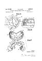
- FIGURE 1 is a top perspective view of a dispensing container constructed in accordance with this invention, and illustrates a closure secured to a neck of a container body.
- FIGURE 2 is an 'enlarged fragmentary top plan view of the dispensing container of FIGURE 1, and illustrates a first relative position between the closure and the container body which prevents the dispensing of a product packaged within the body.
- FIGURE 3 is an enlarged fragmentary sectional view taken generally along line 33 of FIGURE 2 with a portion of the container neck shown in side elevation, and illustrates alternating land and valley portions of the neck imparting a generally undulating configuration to the neck with one of the land. portions closing a selected one of the dispensing openings of the closure.
- FIGURE 4 is a fragmentary sectional view taken generally along line 44 of FIGURE 3, and illustrates abutment means of the closure and neck in contact in a dispensing position of the container.
- FIGURE 5 is a schematic fragmentary top plan view similar to FIGURE 2 and illustrates the abutment means locating the closure and container in a second dispensing position.
- FIGURE 6 is an enlarged fragmentary sectional view taken generally along line 6-6 of FIGURE 5, and illustrates the relationship between a dispensing opening and an associated valley of the neck during a dispensing operation.
- FIGURE 7 is a fragmentary exploded perspective view of the dispensing container, and more clearly illustrates the undulating shape of the container neck and abutment means on the interior of the closure.
- a novel dispensing container constructed inaccordance with this invention is generally referred to by the reference numeral 10 and consists solely of two components, i.e., a container 11 and a closure 12.
- the container 11 andthe closure 12 are preferably constructed from plastic material, such as linear polyethylene or similar thermoplastic material.
- the closure 12 is preferably constructed by conventional injection molding processes and the container 11 is preferably blow-molded.
- the closure 12 of the dispensing container 10 comprises an end wall or panel 13 (FIGURES 3 and 7) having a plurality of dispensing means in the form of dispensing openings 14.
- the dispensing openings 14 are identically circumferentially spaced from each other and each dispensing opening 14 is spaced an identical distance from the axis of the closure 12.
- a depending peripheral skirt 15 (FIGURES 3, 6 and 7) forms an integral portion of the closure 12 depending from the end panel 13.
- the skirt 15 has an exteriorly ribbed gripping portion 16 and an interior surface or wall 17.
- the skirt 15 terminates in an inwardly directed circumferential locking rib 20 above which, as viewed in FIGURES 3, 6 and 7 of the drawings, is an annular groove 21 opening radially inwardly toward the axis of the closure 12.
- a plurality of radially inwardly directed identical projections 22 form an integral portion of the skirt 15 and project radially beyond the internal surface 17 thereof.
- the projections 22 serve as abutment means cooperable with the container 11, as will appear more fully hereafter, to accurately locate the closure 12 in dispensing and nondispensing positions.
- the container 11 comprises a container body 25 having an upper shoulder 26 (FIGURES 1 and 7) merging in an upstanding neck or finish, generally referred to by the reference numeral 27.
- the neck 27 includes an outer surface 28, an inner surface 30 and a terminal peripheral surface or edge 31.
- the edge 31 defines a dispensing mouth or opening (unnumbered) of the container 11.
- the neck 27 of the container body 25 includes a generally circumferentially radially outwardly directed rib 32 which is snap-fit in the groove 21 of the closure 12, as is best illustrated in FIGURES 3 and 6 of the drawings.
- the circumferential rib 32 and the groove 21 form interlocking means for securing the closure 12 upon the neck 27 while permitting relative rotation therebetween, and also form a seal to prevent a product (not shown) packaged in the container 11 from leaking outwardly between the outer surface 28 of the neck 27 in the inner surface 17 of the closure 12 in a dispensing position as will be more apparent hereafter.
- the neck 27 of the container body 25 includes a plurality of upstanding protuberances 33 through 38 (FIG- URE 2) defining lands or land portions adjacent axially lower valley or valley portions 43 through 48.
- Each of the valleys 43 through 48 is substantially identical, but the lands 33 and 36 differ slightly from the lands 34, 35, 37 and 38.
- Each of the lands 33 and 36 includes an axially upstanding radially outermost wall 50 integrally joined to radially inwardly directed axial-1y upstanding walls 51 and 52 and an uppermost or top wall 53, as is best illustrated in FIGURES 2, 3, and 7 of the drawings.
- the walls 5053 define a generally rectangular chamber (unnumbered) in each of the lands 33 and 36.
- the walls' 51 and 52 of the lands 33 and 36 form abutment means or stops for the protuberances or projections 22 of the closure 12 in a manner to be described more fully hereafter.
- Each of the lands 34, 35, 37 and 38 comprises an axially upstanding radially outermost wall 54, upstanding side walls 55 and 56, and an upper or top wall 57.
- the side wall 55 of each of the lands 34, 35, 37 and 38 defines an abutment cooperative with the projections 22 of the closure 12. However, no abutting function is performed by the side walls 56 of the lands 34, 35, 37 and 38.
- the valleys 43 through 48 are each defined by an axially upstanding wall 60 between the side walls of adjacent ones of the lands, as is best exemplified by the wall 60 of the valley between the side wall 56 of the land 35 and the side wall 51 of the land 36 in FIGURE 7 of the drawings.
- the shorter axial height of the walls 60 relative to the height of the lands 33 through 38 defines gaps or openings (unnumbered) between adjacent ones of the lands 33 through 38 through which a product packaged in the container body 25 may fiow during a dispensing operation to be described hereafter. Because of the difference in the height of the walls 60 defining the valleys 43 through 48 and the height of the lands 33 through 38 the terminal surface or edge 31 is generally undulating and imparts an undulating appearance to the neck 27.
- the lands 33 through 38 and the valleys 43 thorugh 48 are spaced substantially identical radial distances from the container body axis and this radial distance corresponds to the radial distance between each of the dispensing openings 14 of the closure 12 and the axis thereof. Because of this dimensioning the dispensing openings 14 selectively overlie the lands 33 through 38 in a first non-dispensing position and, upon rotation of the closure 12 to a second dispensing position, overlie the valleys 43 through 48 as will appear more fully immediately hereafter.
- the closure 12 is fitted upon the neck 27 of the container 11 in the manner best illustrated in FIGURES 2 and 3 of the drawings with the projections 22 occupying a position in an associated one of the valleys 43 through 48 radially outwardly of the associated walls 66 and in a position for abutment with the side walls 51, 52 and 56 (FIGURE 2).
- the projections 22 In the non-dispensing position of the closure 12 (FIGURES 2 through 4) selective ones of the projections 22 are in contact with the walls 51 of the lands 33 and 36, the latter not being illustrated, while others of the projections 22 are in contact with the side walls of the lands 35 and 38, only the latter being illustrated in FIGURE 2 of the drawings.
- This contact between the projections 22 and the noted lands accurately positions each of the dispensing openings 14 over the top walls 53 of the lands 33 and 36 and the top walls 57 of the lands 34, 35, 38 and 37.
- the top walls 53, 57 thereby close an associated dispensing opening 14 in the manner best illustrated in FIGURES 3 and 4 of the drawings in the non-dispensing position of the closure 12 and prevent a product packaged in the container body 25 from passing outwardly through the dispensing openings 14.
- FIGURE 6 of the drawings which illustrates one of the dispensing openings 14 overlying the valley 48.
- Others of the projections 22 of the closure 12 are in abutment with the side walls 52 of the lands 33 and 36 and the sidewalls 55 of the lands 34 and 37 (FIGURE 5) to accurately locate the dispensing openings 14 over the valleys 43 through 48.
- the product which is generally of a powdery nature, passes between each of the walls 60 and the undersurface (unnumbered) of the closure end panel 13 between adjacent ones of the lands 33 through 38 but, as is readily apparent from FIGURES 6 and 7 of the drawings, the walls 60 may be reduced in height or completely eliminated without effecting the function of the dispensing container 10.
- the dispensible product is prevented from leaking outwardly between the inner surface 17 of the closure 12 and the exterior surface 28 of the container neck 27 by the sealing contact of the rib 32 with an upper annular surface 63 and a peripheral surface 64 of the groove 21, as is best illustrated in FIGURE 6 of the drawings.
- the surfaces 63 and 64 also form primary and secondary seals respectively for preventing any material entrapped in the valleys 48 from similarly leaking outwardly in the closed or non-dispensing position of the closure 12, as is readily apparent from FIGURE 3 of the drawings.
- a dispensing container comprising a container body and a closure, said container body having a neck terminating axially in at least one valley and one land portion, said land portion including at least one wall, at least one dispensing opening in said closure, said closure being mounted for rotation relative to said container body, said dispensing opening being closed by said land portion in a first non-dispensing position of said closure and being placed in communication with said body by means of said valley portion in a second dispensing position of said closure, and said closure including means positioned in rotational alignment with at least one wall of said land portion for limiting the rotation of said closure in at least one direction by the contact between said last-mentioned means and said one wall.
- the dispensing container as defined in claim 1 including means between said neck and closure for preventing the leakage of a product outwardly of said dispensing container in the second position of said closure except through said dispensing opening.
- a dispensing container comprising a container body and a closure, said container body having a neck defining a mouth opening of said body, said neck including an inner surface, an outer surface and a terminal peripheral surface, said terminal peripheral surface having alternating high and low surface portions forming alternating lands and valleys respectively about the periphery of the neck imparting a generally undulating configuration thereto, means mounting said closure for rotation relative to said neck, an end panel of said closure overlying said terminal peripheral surface, a plurality of dispensing openings in said end panel, at least one of said dispensing openings being closed by one of said lands in a first non-dispensing position of said closure and said at least one dispensing opening being placed in communication with the interior of said body by means of at least one of said valleys in a second dispensing position of said closure, said closure having a depending peripheral skirt externally surrounding said neck, means between said skirt and neck for preventing the leakage of a product outwardly therebetween in the second position of said closure, means for accurately locating
- a dispensing container comprising a body and a closure, said body having a generally cylindrical neck, a plurality of axially upstanding circumferentially spaced protuberances forming a portion of said neck, said protuberances defining radially inwardly opening recess means, adjacent ones of said protuberances defining a plurality of circumferentially spaced valleys, said closure having an end panel provided with a plurality of dispensing openings and the radial distance between the axis of said closure and the dispensing openings therein corresponding to the radial distance between the axis of said body and said protuberances and valleys whereby said openings selectively overlie said protuberances and valleys in respective non-dispensing and dispensing positions of said container.
- dispensing closure as defined in claim 4 wherein said dispensing container consists solely of a two-piece construction, and said body is constructed from blowmolded polymeric material.
- the container as defined in claim 4 including means spanning said valleys and integrally joined to adjacent pairs of said land portions for reinforcing the neck wall of said container body.
- a dispensing container comprising a container body and a closure, said container body having a neck defining a mouth opening of said body, said neck including an inner surface, an outer surface and a terminal peripheral surface, said terminal peripheral surface having alternating high and low surface portions forming alternating lands and valleys respectively about the periphery of the neck imparting a generally undulating configuration thereto, means mounting said closure for rotation relative to said neck, an end panel of said closure overlying said terminal peripheral surface, at least a single dispensing opening in said end panel, said dispensing opening being closed by one of said lands in a first non-dispensing position of said closure and being placed in communication with the interior of said body by means of one of said valleys in a second dispensing position of said closure, said closure having a depending peripheral skirt externally surrounding said neck, means for accurately locating said dispensing opening over said one land and valley in respective relative first and second positions therebetween, said locating means comprising abutment surfaces of said lands directed generally radially outwardly from
- ROBERT B REEVES, Primary Examiner.
Landscapes
- Engineering & Computer Science (AREA)
- Mechanical Engineering (AREA)
- Closures For Containers (AREA)
Description
Jan. 10, 1967 ALLEN 3,297,214
DISPENSING CONTAINER HAVING A ROTARY FLOW CONTROLLER Filed March 19, 1965 2 Sheets-Sheet 1 as '43 m] $9 INVENTOR RICHARD C. ALLEN Jan. 10, 1967 R. c. ALLEN 3,297,214
DISPENSING CONTAINER HAVING A ROTARY FLOW CONTROLLER Filed March 19, 1965 2 Sheeis-Sheet 2 INVENTOR RICHARD C. ALLEN BY W 4 1 g 74/ w [MVM ML/ ATTORNEYS United States Patent 3,297,214 DISPENSING CONTAINER HAVING A ROTARY FLOW CONIRGLLER Richard C. Alien, Glen Ellyn, Ill., assignor to Continental Can Company, Inc., New York, N.Y., a corporation of New York Filed Mar. 19, 1965, Ser. No. 441,010 8 Claims. (Cl. 222-548) This invention relates to a novel dispensing container formed solely of a container body and a dispensing closure, and is particularly directed to forming lands and valleys in a terminal peripheral portion of the container neck which are selectively cooperative with dispensing openings in the closure to permit product dispensing when the dispensing openings are in registration with the valleys and to prevent product dispensing when the dispensing openings are in registration with the lands.
It is conventional to form dispensing containers which are generally of a three-part construction including a container body and a pair of caps which are generally telescoped relative to each other. One of the caps, generally an innermost cap, is secured to the neck of the container to prevent rotation of the inner cap with respect to the container. The second of the caps, generally the outermost cap, is telescoped externally'of the innermost cap and the container neck, and is mounted for rotation relative to both the innermost cap and the neck of the container.
Both the inner and outer caps are provided with dispensing openings which are in registration in a dispensing position and are out of registration with each other in a non-dspensing position.
Such conventional dispensing contain rs generally include many inherent disadvantages as, for example, the relatively high cost of manufacturing each of the three elements and thereafter preassembling the two caps, as is customary, and then assembling the preassembled caps upon the container. From both a practical and economical standpoint, it can be recognized that to construct such conventional dispensing containers from less than the usual three components would be highly desirable from a manufacturing standpoint, particularly if a dispensing container of fewer than three components is as efiicient and commercially acceptable as known dispensing containers. Furthermore, in the case of dispensing containers formed from plastic material by known molding processes, the less components required represents a significant saving in the cost of the molding dies.
It is, therefore, a primary object of this invention to provide a novel dispensing container which is of a twopiece construction including a container body and a single closure, the container body having a neck terminating in a peripheral portion which is generally undulating in configuration to define land portions and valley portions, the closure having an end panel provided with a plurality of dispensing openings, and the dispensing openings of the closure being selectively positionable into overlying relationship to the =land portions, to prevent a product packaged within the container from being dispensed, and upon rotation of the closure, to present the dispensing openings in overlying relationship to the valley portions to perform a dispensing operation.
A further object of this invention is to provide a novel dispensing container of the type immediately above described including means between the container neck and the closure for preventing the leakage of a packaged product outwardly of the dispensing container in the dispensing position of the closure except for the passage of the product through the dispensing openings.
A further object of this invention is to provide a blowmolded container including a container body having a neck wall defined by an inner surface, an outer surface and a terminal peripheral surface, the'terminal peripheral surface having a plurality of land surface portions and relatively lower valley surface portions in alternating relationship to impart a generally undulating configuration to the neck wall, the container being coop'erable with a closure having an end wall provided with a plurality of dispensing openings which are selectively registrable with the land and valleysurface portions to respectively prevent and permit the dispensing of a product from the container.
A further object of this invention is to provide a novel dispensing container consisting of only a container body and a closure, the container body terminating in a neck, the closure having an end panel overlying the neck, means mounting the -closure on the neck for relative movement therebetween, dispensing means forming a portion of the end panel, the-neck including first means for placing the dispensing means in communication with the interior of the body in a first relative position of the neck and closure, and the neck further including second means for preventing communication between the interior of the body and the dispensing means in a second relative position of the neck and closure whereby selective dispensing of a product in the container body can be'achieved.
With the above, a-n'd'other objects in view that will hereinafter appear, the nature of the invention will be more clearly understood by reference to the following detailed description, the appended claims and the several views illustrated in the accompanying drawings.
In the drawings:
FIGURE 1 is a top perspective view of a dispensing container constructed in accordance with this invention, and illustrates a closure secured to a neck of a container body.
FIGURE 2 is an 'enlarged fragmentary top plan view of the dispensing container of FIGURE 1, and illustrates a first relative position between the closure and the container body which prevents the dispensing of a product packaged within the body.
FIGURE 3 is an enlarged fragmentary sectional view taken generally along line 33 of FIGURE 2 with a portion of the container neck shown in side elevation, and illustrates alternating land and valley portions of the neck imparting a generally undulating configuration to the neck with one of the land. portions closing a selected one of the dispensing openings of the closure.
FIGURE 4 is a fragmentary sectional view taken generally along line 44 of FIGURE 3, and illustrates abutment means of the closure and neck in contact in a dispensing position of the container. V
FIGURE 5 is a schematic fragmentary top plan view similar to FIGURE 2 and illustrates the abutment means locating the closure and container in a second dispensing position. I
FIGURE 6 is an enlarged fragmentary sectional view taken generally along line 6-6 of FIGURE 5, and illustrates the relationship between a dispensing opening and an associated valley of the neck during a dispensing operation.
FIGURE 7 is a fragmentary exploded perspective view of the dispensing container, and more clearly illustrates the undulating shape of the container neck and abutment means on the interior of the closure.
A novel dispensing container constructed inaccordance with this invention is generally referred to by the reference numeral 10 and consists solely of two components, i.e., a container 11 and a closure 12. The container 11 andthe closure 12 are preferably constructed from plastic material, such as linear polyethylene or similar thermoplastic material. The closure 12 is preferably constructed by conventional injection molding processes and the container 11 is preferably blow-molded.
The closure 12 of the dispensing container 10 comprises an end wall or panel 13 (FIGURES 3 and 7) having a plurality of dispensing means in the form of dispensing openings 14. The dispensing openings 14 are identically circumferentially spaced from each other and each dispensing opening 14 is spaced an identical distance from the axis of the closure 12. There are six such dispensing openings 14 illustrated in the drawings (FIGURE 1) but more or less than the number of illustrated dispensing openings can, of course, be provided in the closure 12 in accordance with this invention.
A depending peripheral skirt 15 (FIGURES 3, 6 and 7) forms an integral portion of the closure 12 depending from the end panel 13. The skirt 15 has an exteriorly ribbed gripping portion 16 and an interior surface or wall 17. The skirt 15 terminates in an inwardly directed circumferential locking rib 20 above which, as viewed in FIGURES 3, 6 and 7 of the drawings, is an annular groove 21 opening radially inwardly toward the axis of the closure 12.
A plurality of radially inwardly directed identical projections 22 (FIGURE 7) form an integral portion of the skirt 15 and project radially beyond the internal surface 17 thereof. There are six such projections or lugs 22, not all of which are illustrated, and the projections 22 are equally spaced about the circumference of the skirt 15. The projections 22 serve as abutment means cooperable with the container 11, as will appear more fully hereafter, to accurately locate the closure 12 in dispensing and nondispensing positions.
The container 11 comprises a container body 25 having an upper shoulder 26 (FIGURES 1 and 7) merging in an upstanding neck or finish, generally referred to by the reference numeral 27. The neck 27 includes an outer surface 28, an inner surface 30 and a terminal peripheral surface or edge 31. The edge 31 defines a dispensing mouth or opening (unnumbered) of the container 11.
The neck 27 of the container body 25 includes a generally circumferentially radially outwardly directed rib 32 which is snap-fit in the groove 21 of the closure 12, as is best illustrated in FIGURES 3 and 6 of the drawings. The circumferential rib 32 and the groove 21 form interlocking means for securing the closure 12 upon the neck 27 while permitting relative rotation therebetween, and also form a seal to prevent a product (not shown) packaged in the container 11 from leaking outwardly between the outer surface 28 of the neck 27 in the inner surface 17 of the closure 12 in a dispensing position as will be more apparent hereafter.
The neck 27 of the container body 25 includes a plurality of upstanding protuberances 33 through 38 (FIG- URE 2) defining lands or land portions adjacent axially lower valley or valley portions 43 through 48. There are six such land portions and valley portions illustrated in the drawings, corresponding to the number of dispensing openings 14 in the closure 12. Each of the valleys 43 through 48 is substantially identical, but the lands 33 and 36 differ slightly from the lands 34, 35, 37 and 38.
Each of the lands 33 and 36 includes an axially upstanding radially outermost wall 50 integrally joined to radially inwardly directed axial-1y upstanding walls 51 and 52 and an uppermost or top wall 53, as is best illustrated in FIGURES 2, 3, and 7 of the drawings. The walls 5053 define a generally rectangular chamber (unnumbered) in each of the lands 33 and 36. The walls' 51 and 52 of the lands 33 and 36 form abutment means or stops for the protuberances or projections 22 of the closure 12 in a manner to be described more fully hereafter.
Each of the lands 34, 35, 37 and 38 comprises an axially upstanding radially outermost wall 54, upstanding side walls 55 and 56, and an upper or top wall 57. The side wall 55 of each of the lands 34, 35, 37 and 38 defines an abutment cooperative with the projections 22 of the closure 12. However, no abutting function is performed by the side walls 56 of the lands 34, 35, 37 and 38.
The valleys 43 through 48 are each defined by an axially upstanding wall 60 between the side walls of adjacent ones of the lands, as is best exemplified by the wall 60 of the valley between the side wall 56 of the land 35 and the side wall 51 of the land 36 in FIGURE 7 of the drawings. The shorter axial height of the walls 60 relative to the height of the lands 33 through 38 defines gaps or openings (unnumbered) between adjacent ones of the lands 33 through 38 through which a product packaged in the container body 25 may fiow during a dispensing operation to be described hereafter. Because of the difference in the height of the walls 60 defining the valleys 43 through 48 and the height of the lands 33 through 38 the terminal surface or edge 31 is generally undulating and imparts an undulating appearance to the neck 27. The lands 33 through 38 and the valleys 43 thorugh 48 are spaced substantially identical radial distances from the container body axis and this radial distance corresponds to the radial distance between each of the dispensing openings 14 of the closure 12 and the axis thereof. Because of this dimensioning the dispensing openings 14 selectively overlie the lands 33 through 38 in a first non-dispensing position and, upon rotation of the closure 12 to a second dispensing position, overlie the valleys 43 through 48 as will appear more fully immediately hereafter.
The closure 12 is fitted upon the neck 27 of the container 11 in the manner best illustrated in FIGURES 2 and 3 of the drawings with the projections 22 occupying a position in an associated one of the valleys 43 through 48 radially outwardly of the associated walls 66 and in a position for abutment with the side walls 51, 52 and 56 (FIGURE 2). In the non-dispensing position of the closure 12 (FIGURES 2 through 4) selective ones of the projections 22 are in contact with the walls 51 of the lands 33 and 36, the latter not being illustrated, while others of the projections 22 are in contact with the side walls of the lands 35 and 38, only the latter being illustrated in FIGURE 2 of the drawings. This contact between the projections 22 and the noted lands accurately positions each of the dispensing openings 14 over the top walls 53 of the lands 33 and 36 and the top walls 57 of the lands 34, 35, 38 and 37. The top walls 53, 57 thereby close an associated dispensing opening 14 in the manner best illustrated in FIGURES 3 and 4 of the drawings in the non-dispensing position of the closure 12 and prevent a product packaged in the container body 25 from passing outwardly through the dispensing openings 14.
Upon the rotation of the closure 12 in a counterclockwise direction from the position shown in FIGURE 2 to the position shown in FIGURE 5 a dispensing opening 14 is brought into overlying relationship to an associated one of the valleys 43 through 48, as is best illustrated in FIGURE 6 of the drawings which illustrates one of the dispensing openings 14 overlying the valley 48. Others of the projections 22 of the closure 12 are in abutment with the side walls 52 of the lands 33 and 36 and the sidewalls 55 of the lands 34 and 37 (FIGURE 5) to accurately locate the dispensing openings 14 over the valleys 43 through 48. Upon inverting the dispensing container 10 from the position illustrated in FIGURE 1 in the normal course of the dispensing operation, the product packaged in the container body 25 fiows through the neck, through the valleys 43 through 48, and then through each of the dispensing openings 14 along a flow path best illustrated in FIGURE 6 of the drawings by the headed unnumbered arrow passing from the interior of the neck 27 through the valley 48 and outwardly through the illustrated dispensing opening 14. The product, which is generally of a powdery nature, passes between each of the walls 60 and the undersurface (unnumbered) of the closure end panel 13 between adjacent ones of the lands 33 through 38 but, as is readily apparent from FIGURES 6 and 7 of the drawings, the walls 60 may be reduced in height or completely eliminated without effecting the function of the dispensing container 10.
During the dispensing operation just described the dispensible product is prevented from leaking outwardly between the inner surface 17 of the closure 12 and the exterior surface 28 of the container neck 27 by the sealing contact of the rib 32 with an upper annular surface 63 and a peripheral surface 64 of the groove 21, as is best illustrated in FIGURE 6 of the drawings. The surfaces 63 and 64 also form primary and secondary seals respectively for preventing any material entrapped in the valleys 48 from similarly leaking outwardly in the closed or non-dispensing position of the closure 12, as is readily apparent from FIGURE 3 of the drawings.
From the foregoing, it will be seen that novel and advantageous provisions have been made for carrying out the desired end. However, attention is again directed to the fact that additional variations may be made in this invention without departing from the spirit and scope thereof as defined in the appended claims.
I claim:
1. A dispensing container comprising a container body and a closure, said container body having a neck terminating axially in at least one valley and one land portion, said land portion including at least one wall, at least one dispensing opening in said closure, said closure being mounted for rotation relative to said container body, said dispensing opening being closed by said land portion in a first non-dispensing position of said closure and being placed in communication with said body by means of said valley portion in a second dispensing position of said closure, and said closure including means positioned in rotational alignment with at least one wall of said land portion for limiting the rotation of said closure in at least one direction by the contact between said last-mentioned means and said one wall.
2. The dispensing container as defined in claim 1 including means between said neck and closure for preventing the leakage of a product outwardly of said dispensing container in the second position of said closure except through said dispensing opening.
3. A dispensing container comprising a container body and a closure, said container body having a neck defining a mouth opening of said body, said neck including an inner surface, an outer surface and a terminal peripheral surface, said terminal peripheral surface having alternating high and low surface portions forming alternating lands and valleys respectively about the periphery of the neck imparting a generally undulating configuration thereto, means mounting said closure for rotation relative to said neck, an end panel of said closure overlying said terminal peripheral surface, a plurality of dispensing openings in said end panel, at least one of said dispensing openings being closed by one of said lands in a first non-dispensing position of said closure and said at least one dispensing opening being placed in communication with the interior of said body by means of at least one of said valleys in a second dispensing position of said closure, said closure having a depending peripheral skirt externally surrounding said neck, means between said skirt and neck for preventing the leakage of a product outwardly therebetween in the second position of said closure, means for accurately locating said at least one dispensing opening over said at least one land and valley in said respective first and second positions, and said locating means comprising radial surfaces of said land and radially inwardly directed protuberances of said peripheral skirt alignable for abutment with selected ones of said radial surfaces upon the rotation of said closure between said first and second positions.
4. A dispensing container comprising a body and a closure, said body having a generally cylindrical neck, a plurality of axially upstanding circumferentially spaced protuberances forming a portion of said neck, said protuberances defining radially inwardly opening recess means, adjacent ones of said protuberances defining a plurality of circumferentially spaced valleys, said closure having an end panel provided with a plurality of dispensing openings and the radial distance between the axis of said closure and the dispensing openings therein corresponding to the radial distance between the axis of said body and said protuberances and valleys whereby said openings selectively overlie said protuberances and valleys in respective non-dispensing and dispensing positions of said container.
5. The dispensing closure as defined in claim 4 wherein said dispensing container consists solely of a two-piece construction, and said body is constructed from blowmolded polymeric material.
6. The container as defined in claim 4 including means spanning said valleys and integrally joined to adjacent pairs of said land portions for reinforcing the neck wall of said container body.
7. The dispensing container as defined in claim 4 wherein said closure includes means positioned in at least one of said valleys in rotatable alignment with an adjacent pair of said protuberances for limiting the rotation of said closure between the dispensing and non-dispensing positions thereof.
8. A dispensing container comprising a container body and a closure, said container body having a neck defining a mouth opening of said body, said neck including an inner surface, an outer surface and a terminal peripheral surface, said terminal peripheral surface having alternating high and low surface portions forming alternating lands and valleys respectively about the periphery of the neck imparting a generally undulating configuration thereto, means mounting said closure for rotation relative to said neck, an end panel of said closure overlying said terminal peripheral surface, at least a single dispensing opening in said end panel, said dispensing opening being closed by one of said lands in a first non-dispensing position of said closure and being placed in communication with the interior of said body by means of one of said valleys in a second dispensing position of said closure, said closure having a depending peripheral skirt externally surrounding said neck, means for accurately locating said dispensing opening over said one land and valley in respective relative first and second positions therebetween, said locating means comprising abutment surfaces of said lands directed generally radially outwardly from an axis of said container body, and at least one protuberance of said peripheral skirt alignable for abutment with said abutment surfaces upon the rotation of said closure between said first and second positions.
References Cited by the Examiner UNITED STATES PATENTS 2,449,285 9/1948 Ekstrom 222548 X 3,042,273 7/ 1962 Baurer et al. 222548 3,194,455 7/1965 Castelli 222548 X 3,214,068 10/1965 Armour 222548 X FOREIGN PATENTS 84,650 3/ 1958 Denmark. 325,394 11/ 1957 Switzerland.
ROBERT B. REEVES, Primary Examiner.
WALTER SOBIN, Examiner.
Claims (1)
1. A DISPENSING CONTAINER COMPRISING A CONTAINER BODY AND A CLOSURE, SAID CONTAINER BODY HAVING A NECK TERMINATING AXIALLY IN AT LEAST ONE VALLEY AND ONE LAND PORTION, SAID LAND PORTION INCLUDING AT LEAST ONE WALL, AT LEAST ONE DISPENSING OPENING IN SAID CLOSURE, SAID CLOSURE BEING MOUNTED FOR ROTATION RELATIVE TO SAID CONTAINER BODY, SAID DISPENSING OPENING BEING CLOSED BY SAID LAND PORTION IN A FIRST NON-DISPENSING POSITION OF SAID CLOSURE AND BEING PLACED IN COMMUNICATION WITH SAID BODY BY MEANS OF SAID VALLEY PORTION IN A SECOND DISPENSING POSITION OF SAID CLOSURE, AND SAID CLOSURE INCLUDING MEANS POSITIONED IN ROTATIONAL ALIGNMENT WITH AT LEAST ONE WALL OF SAID LAND PORTION FOR LIMITING THE ROTATION OF SAID CLOSURE IN AT LEAST ONE DIRECTION BY THE CONTACT BETWEEN SAID LAST-MENTIONED MEANS AND SAID ONE WALL.
Priority Applications (2)
| Application Number | Priority Date | Filing Date | Title |
|---|---|---|---|
| US441010A US3297214A (en) | 1965-03-19 | 1965-03-19 | Dispensing container having a rotary flow controller |
| FR54074A FR1471755A (en) | 1965-03-19 | 1966-03-18 | Two-piece dispensing container |
Applications Claiming Priority (1)
| Application Number | Priority Date | Filing Date | Title |
|---|---|---|---|
| US441010A US3297214A (en) | 1965-03-19 | 1965-03-19 | Dispensing container having a rotary flow controller |
Publications (1)
| Publication Number | Publication Date |
|---|---|
| US3297214A true US3297214A (en) | 1967-01-10 |
Family
ID=23751124
Family Applications (1)
| Application Number | Title | Priority Date | Filing Date |
|---|---|---|---|
| US441010A Expired - Lifetime US3297214A (en) | 1965-03-19 | 1965-03-19 | Dispensing container having a rotary flow controller |
Country Status (1)
| Country | Link |
|---|---|
| US (1) | US3297214A (en) |
Cited By (2)
| Publication number | Priority date | Publication date | Assignee | Title |
|---|---|---|---|---|
| US3389840A (en) * | 1966-04-27 | 1968-06-25 | Robert J. Musel | Combined dispensing container and closure |
| US3851806A (en) * | 1973-04-02 | 1974-12-03 | Continental Can Co | Dispenser with nozzle cut-off |
Citations (5)
| Publication number | Priority date | Publication date | Assignee | Title |
|---|---|---|---|---|
| US2449285A (en) * | 1944-07-17 | 1948-09-14 | Clark Mfg Co J L | Rotary sifter top |
| CH325394A (en) * | 1954-11-17 | 1957-11-15 | Gimelli & Co | Shaker |
| US3042273A (en) * | 1959-03-30 | 1962-07-03 | Borden Co | Flanged closure cap for resiliently yieldable plastic container |
| US3194455A (en) * | 1963-11-22 | 1965-07-13 | Johnson & Johnson | Container with sifter top |
| US3214068A (en) * | 1963-12-17 | 1965-10-26 | Monsanto Co | Shaker |
-
1965
- 1965-03-19 US US441010A patent/US3297214A/en not_active Expired - Lifetime
Patent Citations (5)
| Publication number | Priority date | Publication date | Assignee | Title |
|---|---|---|---|---|
| US2449285A (en) * | 1944-07-17 | 1948-09-14 | Clark Mfg Co J L | Rotary sifter top |
| CH325394A (en) * | 1954-11-17 | 1957-11-15 | Gimelli & Co | Shaker |
| US3042273A (en) * | 1959-03-30 | 1962-07-03 | Borden Co | Flanged closure cap for resiliently yieldable plastic container |
| US3194455A (en) * | 1963-11-22 | 1965-07-13 | Johnson & Johnson | Container with sifter top |
| US3214068A (en) * | 1963-12-17 | 1965-10-26 | Monsanto Co | Shaker |
Cited By (2)
| Publication number | Priority date | Publication date | Assignee | Title |
|---|---|---|---|---|
| US3389840A (en) * | 1966-04-27 | 1968-06-25 | Robert J. Musel | Combined dispensing container and closure |
| US3851806A (en) * | 1973-04-02 | 1974-12-03 | Continental Can Co | Dispenser with nozzle cut-off |
Similar Documents
| Publication | Publication Date | Title |
|---|---|---|
| US3104039A (en) | Plastic captive seal closure and spout | |
| US4489844A (en) | Crew-type all plastic closure | |
| US4526281A (en) | Moisture tight closure and container | |
| US3298415A (en) | Closures for large mouth containers | |
| US3696957A (en) | Fluid-tight, flexible and tamper-proof caps for containers having a matching neck profile | |
| US3901400A (en) | Childproof closure | |
| US3993209A (en) | Child-resistant cap | |
| CA1127112A (en) | Beaded snaplock closure | |
| US4699299A (en) | Adjustable dispensing closure | |
| US3439841A (en) | Multiple container package | |
| US6164503A (en) | Closure for liquids | |
| US4917268A (en) | Liquid dispensing package with drainback spout | |
| US4053078A (en) | Child safety closure | |
| US4397397A (en) | Moisture tight closure and container systems | |
| US6896160B2 (en) | Lockable disc top dispensing closure | |
| US3467287A (en) | Rotatable closure assembly with rim | |
| US3907146A (en) | Primary closure | |
| US3325066A (en) | Dispensing container having a rotary closure cap | |
| US3285452A (en) | Container finish and closure cap construction | |
| US4436211A (en) | Safety package | |
| US3189071A (en) | Flexible dispensing container assemblies | |
| US3365106A (en) | Dispensing container with axially rotary closure for plural dispensing outlets | |
| US3260426A (en) | Container closure comprising a stationary apertured cap and a rotary apertured cap | |
| US3342383A (en) | Dispenser for granular materials | |
| US3297214A (en) | Dispensing container having a rotary flow controller |