US329053A - Rope-reel - Google Patents
Rope-reel Download PDFInfo
- Publication number
- US329053A US329053A US329053DA US329053A US 329053 A US329053 A US 329053A US 329053D A US329053D A US 329053DA US 329053 A US329053 A US 329053A
- Authority
- US
- United States
- Prior art keywords
- reel
- rope
- slots
- disks
- rods
- Prior art date
- Legal status (The legal status is an assumption and is not a legal conclusion. Google has not performed a legal analysis and makes no representation as to the accuracy of the status listed.)
- Expired - Lifetime
Links
Images
Classifications
-
- B—PERFORMING OPERATIONS; TRANSPORTING
- B65—CONVEYING; PACKING; STORING; HANDLING THIN OR FILAMENTARY MATERIAL
- B65H—HANDLING THIN OR FILAMENTARY MATERIAL, e.g. SHEETS, WEBS, CABLES
- B65H75/00—Storing webs, tapes, or filamentary material, e.g. on reels
- B65H75/02—Cores, formers, supports, or holders for coiled, wound, or folded material, e.g. reels, spindles, bobbins, cop tubes, cans, mandrels or chucks
- B65H75/18—Constructional details
- B65H75/24—Constructional details adjustable in configuration, e.g. expansible
- B65H75/242—Expansible spindles, mandrels or chucks, e.g. for securing or releasing cores, holders or packages
- B65H75/246—Expansible spindles, mandrels or chucks, e.g. for securing or releasing cores, holders or packages expansion caused by relative rotation around the supporting spindle or core axis
Definitions
- WVILLIAM M. KIZER AND CHARLES ⁇ V. OLINK, OF WVINFIELD, MICHIGAN.
- the object of our invention is to provide a collars D D, and we make the shaft round at simple, inexpensive, and efficient reel device each end outside of the collars, to form end 10 for holding coils of rope or twine for the eonjournals, b b, which may enter suitable bearvenience of storekeepers and others in tying ings in a stand for supporting the reel clear up packages or retailing the rope. of the table, counter, or floor, so that the reel
- the invention consists in a rope or twine may turn as the twine or rope is unwound reel constructed with connected end frames fromit,
- each of the arms a has a lengthwise slot, F, mounted next the end. frames and provided near the joint of the arms with each other with cam or eccentric slots,and cross-rods enand radiating from the central shaft, B, and tering the radial and eccentric slots, so that each of the end disks, 0 O, has a series of ecupon turning the disks the rods may be eX- centric or cam slots, G, corresponding in num-- o panded to tighten within the coil of rope. ber with the radial slots F of the adjacent end
- the invention consists, also, in various deframe of the reel.
- cam-slots G of the opposite disks'G C we have arranged the cam-slots G of the opposite disks'G C, so that the disks are to be turned by their handles to la in reverse directions to expand the rods H evenly or parallel with each other; consequently the opposite pawls I I and their respective ratchet-teeth c c on the disks are reversely arranged; but it is evident that the cam-slots of the opposite disks may be arranged to expand the rods H by a movement of bothdisks in the same direction, in which case the opposite end pawls and ratchet-teeth will be arranged alike. On raising the .pawls from the teeth the bars H may be moved inward or toward each other again by a reverse motion of the cam-slot disks, as will be readily understood.
- the end frame A with its disk 0, may be moved to any point along the shaft B, and there held by its collar D, so that coils of twine or rope of any size may be clamped between the end frames to be unwound from the reel, as required for use.
- a rope-reel constructed withconnected end frames having radial slots, rotatable disks or plates mounted at the sides of the end 0 frames and provided with cam or eccentric slots, and rods for supporting the rope coil entered into the radial and cam slots of the end frames and disks, respectively, substantially as herein sh own and described.
Landscapes
- Storage Of Web-Like Or Filamentary Materials (AREA)
Description
(No Model.)
W. M. KIZER &-G. W. (BLINK.
ROPE'REEL. l
y No. 329,053. Patented 001;. 27, 18815.
' INVENTOR: V W
ATTORNEYS.
UNITED STATES PATENT OFFICE,
WVILLIAM M. KIZER AND CHARLES \V. OLINK, OF WVINFIELD, MICHIGAN.
ROPE-REEL.
SPECIFICATION forming part of Letters Patent No. 329,053, dated October 27, 1885.
Application filed July 12, 1884. Serial No. 137,587. (No model) I aZZ whom it may concern: Suitable collars or thimbles, D D, are placed Be it known that we, WILLIAM M. KIZER on the shaft B outside of the disks 0 O, and and CHARLES W. CLINK, of Winfield, in the these collars have set-screws d d, by which county of Montcalm and State of Michigan, they, may be fixed on the shaft to hold the 5 5 haveinventedanew and Improved Rope-Bee], disks in place on their hub-bearings.
of which the followingis afull, clear, and exact We prefer to make the shaftBsqu are in crossdescription. section between the outer ends of the opposite The object of our invention is to provide a collars D D, and we make the shaft round at simple, inexpensive, and efficient reel device each end outside of the collars, to form end 10 for holding coils of rope or twine for the eonjournals, b b, which may enter suitable bearvenience of storekeepers and others in tying ings in a stand for supporting the reel clear up packages or retailing the rope. of the table, counter, or floor, so that the reel The invention consists in a rope or twine may turn as the twine or rope is unwound reel constructed with connected end frames fromit,
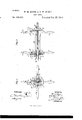
15 provided with radial slots, rotatable disks Each of the arms a has a lengthwise slot, F, mounted next the end. frames and provided near the joint of the arms with each other with cam or eccentric slots,and cross-rods enand radiating from the central shaft, B, and tering the radial and eccentric slots, so that each of the end disks, 0 O, has a series of ecupon turning the disks the rods may be eX- centric or cam slots, G, corresponding in num-- o panded to tighten within the coil of rope. ber with the radial slots F of the adjacent end The invention consists, also, in various deframe of the reel. tails of construction and combination of parts Before the end disk 0 is applied to the of the reel, whereby it is made extensible or reel-shaftoutside of the end frame A a rod, adjustable endwise, and may be readily dis- H, is passed through the slot F of each arm a 2 membered to receive the rope coil, and whereof the frame until a collar, h, on the rod comes by also the rods may be held fully expanded against the face of the arm. The disk 0 then and securely against the inside of the coil, all is placed on its hub-bearing b, and so that the as hereinafter fully described and claimed. ends h of all the rods H will pass into the in- Reference is to be had to the accompanying ner ends, of the corresponding cam-slots G,
3o drawings, forminga part of this specification, the rods then being on the inner ends, f, of in which similar letters of reference indicate the slots F. The opposite end frame, A, and corresponding parts in both the figures. the disk 0 will then be passed upon the shaft Figure 1 is an end elevation of our improved B, and with the ends h of the rods H passed rope-reel, and Fig. 2 is a longitudinal and into the inner ends of the radial and cam slots 3 5 partly sectional elevation of the same. of the frame A and disk 0, respectively, and The letters A A indicate, respectively, the the collar or thimble D will then be fixed on I, two end frames of the reel, each of which are the shaft outside of the disk 0. The coil of made in the example shown of a pair of bars rope or twine is slipped onto or around the framed together at their centers and at right rods H before the end frame A is placed on c 40 angles to each other, and so as to form the the shaft.
four arms a a a a, which may be shaped as With this construction, when the opposite handles at their outer ends. WVe connect the end disks are turned, the eccentric or cam end frames, A A, by a central shaft, B, and slots of the disks 0 (3 will carry the rods H we propose to mount the end frame A tightly outward along the radial slots of the reel- 5 45 ontheshaft, and the opposite frame, A, loosely frames A A and spread the several rods H thereon. apart, so as to take hold of the inside of the On the centers of the end frames, A A, and coil of twine or rope to bind it firmly to the at the outside face, we fix or form hubs b b, on reel, so as to revolve only as the reel revolves, which are mounted so as to turn freely the and not' slip around the reel, which would 5c disks or plates 0 0, outside of the respective quickly entangle the twine.
end frames, A A. To hold the rods H expanded tightly to the inside of the coil of twine or rope, we provide pawls I I for the respective end frames, which pawls are pivoted on pins z 2', respectively, to one of the arms a of each frame, and engage ratohetteeth c on the end disks, 0 O. Springs j j, made preferably of elastic wire and fastened to the arms of the end frames, hold the pawls into the ratchet-teeth.
' We have arranged the cam-slots G of the opposite disks'G C, so that the disks are to be turned by their handles to la in reverse directions to expand the rods H evenly or parallel with each other; consequently the opposite pawls I I and their respective ratchet-teeth c c on the disks are reversely arranged; but it is evident that the cam-slots of the opposite disks may be arranged to expand the rods H by a movement of bothdisks in the same direction, in which case the opposite end pawls and ratchet-teeth will be arranged alike. On raising the .pawls from the teeth the bars H may be moved inward or toward each other again by a reverse motion of the cam-slot disks, as will be readily understood.
The end frame A, with its disk 0, may be moved to any point along the shaft B, and there held by its collar D, so that coils of twine or rope of any size may be clamped between the end frames to be unwound from the reel, as required for use.
There may be more or less than four of the rods H, as shown, and the number of the slots F G at each end of the reel will of course cor respond with the number of the rods.
Having thus described our invention, we
claim as new and desire to secure by Letters Patent- 1. A rope-reel constructed withconnected end frames having radial slots, rotatable disks or plates mounted at the sides of the end 0 frames and provided with cam or eccentric slots, and rods for supporting the rope coil entered into the radial and cam slots of the end frames and disks, respectively, substantially as herein sh own and described.
2. The combination, in a rope-reel, of the connected end frames, A A, having radial slots F, the disks 0 0, having cam-slots G, and the rods H, entering the slots F G, substantially as herein shown and described. so
3. The combination, in a rope-reel, of the end frame, A, provided with slots F and fixed to the shaft B, the disk 0. having slots G and mounted to turn 011 a hearing, I), of the frame A, the rods H, passed through the slots F G of frame A and provided with the collars it between the frame and the disk, the collar D, fixed to the shaft B outside of the disk 0, the loosely-mounted and correspondingly-slotted end frame, A, and rotatable disk 0, and the collar D, substantially as shown and described. 4. The combination, with the radially-slotted end frames, A A, and eccentrically-slotted disks 0 O, of the spring-pawls I I, substantially as shown and described.
WILLIAM M. KIZER. CHARLES W. GLINK. Witnesses:
LEROY L. KIZER, ORVILLE BALL.
Publications (1)
| Publication Number | Publication Date |
|---|---|
| US329053A true US329053A (en) | 1885-10-27 |
Family
ID=2398163
Family Applications (1)
| Application Number | Title | Priority Date | Filing Date |
|---|---|---|---|
| US329053D Expired - Lifetime US329053A (en) | Rope-reel |
Country Status (1)
| Country | Link |
|---|---|
| US (1) | US329053A (en) |
Cited By (12)
| Publication number | Priority date | Publication date | Assignee | Title |
|---|---|---|---|---|
| US2650771A (en) * | 1949-05-11 | 1953-09-01 | Kenneth O Marion | Wire reeling machine |
| US2819760A (en) * | 1954-04-13 | 1958-01-14 | Onnig M Norehad | Cutting machine |
| US5341998A (en) * | 1992-06-02 | 1994-08-30 | The Boeing Company | Pin hub for wire reel |
| CN107324127A (en) * | 2017-06-19 | 2017-11-07 | 杭州欣源电梯部件有限公司 | A kind of steel wire rope for elevator core actinobacillus device of variable-diameter |
| US20180134514A1 (en) * | 2016-11-14 | 2018-05-17 | The Boeing Company | Rotational wire transport for automated wire processing system and methods |
| CN112249809A (en) * | 2020-10-16 | 2021-01-22 | 南京晨荣电子商务有限公司 | Auxiliary device is used in production of twisted-pair line that intelligence was made |
| CN112607513A (en) * | 2020-12-16 | 2021-04-06 | 江苏省镔鑫钢铁集团有限公司 | Spiral steel spinning conveying and packaging system and packaging device |
| US11069462B2 (en) | 2016-12-15 | 2021-07-20 | The Boeing Company | Automated wire processing system and methods |
| CN114380137A (en) * | 2022-01-14 | 2022-04-22 | 杭州惠尔线缆有限公司 | Cable packing plate |
| US11322278B2 (en) | 2016-12-15 | 2022-05-03 | The Boeing Company | Automated wire processing system |
| EP4095077A1 (en) * | 2021-05-27 | 2022-11-30 | Scientific Anglers LLC | Spool assembly |
| US11569009B2 (en) | 2016-12-15 | 2023-01-31 | The Boeing Company | Automated wire processing system and methods |
-
0
- US US329053D patent/US329053A/en not_active Expired - Lifetime
Cited By (16)
| Publication number | Priority date | Publication date | Assignee | Title |
|---|---|---|---|---|
| US2650771A (en) * | 1949-05-11 | 1953-09-01 | Kenneth O Marion | Wire reeling machine |
| US2819760A (en) * | 1954-04-13 | 1958-01-14 | Onnig M Norehad | Cutting machine |
| US5341998A (en) * | 1992-06-02 | 1994-08-30 | The Boeing Company | Pin hub for wire reel |
| US10301146B2 (en) * | 2016-11-14 | 2019-05-28 | The Boeing Company | Rotational wire transport for automated wire processing system and methods |
| US20180134514A1 (en) * | 2016-11-14 | 2018-05-17 | The Boeing Company | Rotational wire transport for automated wire processing system and methods |
| US11069462B2 (en) | 2016-12-15 | 2021-07-20 | The Boeing Company | Automated wire processing system and methods |
| US11322278B2 (en) | 2016-12-15 | 2022-05-03 | The Boeing Company | Automated wire processing system |
| US11569009B2 (en) | 2016-12-15 | 2023-01-31 | The Boeing Company | Automated wire processing system and methods |
| CN107324127A (en) * | 2017-06-19 | 2017-11-07 | 杭州欣源电梯部件有限公司 | A kind of steel wire rope for elevator core actinobacillus device of variable-diameter |
| CN107324127B (en) * | 2017-06-19 | 2024-01-09 | 杭州欣源电梯部件有限公司 | Variable-diameter steel wire rope core paying-off device for elevator |
| CN112249809A (en) * | 2020-10-16 | 2021-01-22 | 南京晨荣电子商务有限公司 | Auxiliary device is used in production of twisted-pair line that intelligence was made |
| CN112607513A (en) * | 2020-12-16 | 2021-04-06 | 江苏省镔鑫钢铁集团有限公司 | Spiral steel spinning conveying and packaging system and packaging device |
| CN112607513B (en) * | 2020-12-16 | 2022-06-28 | 江苏省镔鑫钢铁集团有限公司 | A kind of coiled steel wire spinning conveying and packing system and packing device |
| EP4095077A1 (en) * | 2021-05-27 | 2022-11-30 | Scientific Anglers LLC | Spool assembly |
| US12157655B2 (en) | 2021-05-27 | 2024-12-03 | Scientific Anglers Llc | Spool assembly |
| CN114380137A (en) * | 2022-01-14 | 2022-04-22 | 杭州惠尔线缆有限公司 | Cable packing plate |
Similar Documents
| Publication | Publication Date | Title |
|---|---|---|
| US329053A (en) | Rope-reel | |
| US1286085A (en) | Line-drying reel. | |
| US325394A (en) | Reel for holding wire in the coil | |
| US718159A (en) | Folding cot. | |
| US711651A (en) | Wire-stretcher. | |
| US1227466A (en) | Self-winding hose-reel. | |
| US9096968B1 (en) | Portable clothesline system for heavy garments | |
| CN111380317A (en) | Linkable rack and refrigerator using the rack | |
| US849066A (en) | Display-rack. | |
| US272263A (en) | Island | |
| US1219658A (en) | Skein-holder. | |
| US532130A (en) | Clothes-line reel | |
| US337637A (en) | Reel for fence-making machines | |
| US1021606A (en) | Reel. | |
| US411343A (en) | Benjamin e | |
| CN104900979B (en) | C-type carbon fiber support tube for space development parabolic-cylinder antenna rolls up extending apparatus | |
| US1729171A (en) | Evergreen-wreath-making machine | |
| US857089A (en) | Wire-cloth reel. | |
| US1323652A (en) | Lace and ribbon winder | |
| US681767A (en) | Fence-machine. | |
| US867959A (en) | Line-drier. | |
| US454027A (en) | Spring-bed | |
| US705634A (en) | Wire-stretcher. | |
| US1340064A (en) | Wire-winding device | |
| US966723A (en) | Bed spring and frame. |