US3290532A - Conjointly-movable, plural magnet means for blue lateral correction in color kinescopes - Google Patents
Conjointly-movable, plural magnet means for blue lateral correction in color kinescopes Download PDFInfo
- Publication number
- US3290532A US3290532A US362092A US36209264A US3290532A US 3290532 A US3290532 A US 3290532A US 362092 A US362092 A US 362092A US 36209264 A US36209264 A US 36209264A US 3290532 A US3290532 A US 3290532A
- Authority
- US
- United States
- Prior art keywords
- magnet
- magnets
- pair
- neck
- cylindrical
- Prior art date
- Legal status (The legal status is an assumption and is not a legal conclusion. Google has not performed a legal analysis and makes no representation as to the accuracy of the status listed.)
- Expired - Lifetime
Links
- 230000002093 peripheral effect Effects 0.000 claims description 20
- 230000005291 magnetic effect Effects 0.000 description 26
- 239000013598 vector Substances 0.000 description 12
- 230000000694 effects Effects 0.000 description 7
- OAICVXFJPJFONN-UHFFFAOYSA-N Phosphorus Chemical compound [P] OAICVXFJPJFONN-UHFFFAOYSA-N 0.000 description 6
- 238000010586 diagram Methods 0.000 description 6
- 238000013459 approach Methods 0.000 description 5
- 230000004907 flux Effects 0.000 description 5
- 230000002301 combined effect Effects 0.000 description 3
- 230000000717 retained effect Effects 0.000 description 3
- 230000003068 static effect Effects 0.000 description 3
- 238000010894 electron beam technology Methods 0.000 description 2
- 238000004904 shortening Methods 0.000 description 2
- 239000013589 supplement Substances 0.000 description 2
- LLBZPESJRQGYMB-UHFFFAOYSA-N 4-one Natural products O1C(C(=O)CC)CC(C)C11C2(C)CCC(C3(C)C(C(C)(CO)C(OC4C(C(O)C(O)C(COC5C(C(O)C(O)CO5)OC5C(C(OC6C(C(O)C(O)C(CO)O6)O)C(O)C(CO)O5)OC5C(C(O)C(O)C(C)O5)O)O4)O)CC3)CC3)=C3C2(C)CC1 LLBZPESJRQGYMB-UHFFFAOYSA-N 0.000 description 1
- 206010061307 Neck deformity Diseases 0.000 description 1
- 230000009471 action Effects 0.000 description 1
- 230000001154 acute effect Effects 0.000 description 1
- 230000004075 alteration Effects 0.000 description 1
- 230000003292 diminished effect Effects 0.000 description 1
- 239000003292 glue Substances 0.000 description 1
- 238000007689 inspection Methods 0.000 description 1
- 230000003993 interaction Effects 0.000 description 1
- 239000000696 magnetic material Substances 0.000 description 1
- 238000012423 maintenance Methods 0.000 description 1
- 238000004519 manufacturing process Methods 0.000 description 1
- 239000000463 material Substances 0.000 description 1
- 238000000034 method Methods 0.000 description 1
- 230000008569 process Effects 0.000 description 1
- 238000007493 shaping process Methods 0.000 description 1
Images

Classifications
-
- H—ELECTRICITY
- H01—ELECTRIC ELEMENTS
- H01J—ELECTRIC DISCHARGE TUBES OR DISCHARGE LAMPS
- H01J29/00—Details of cathode-ray tubes or of electron-beam tubes of the types covered by group H01J31/00
- H01J29/46—Arrangements of electrodes and associated parts for generating or controlling the ray or beam, e.g. electron-optical arrangement
- H01J29/70—Arrangements for deflecting ray or beam
- H01J29/701—Systems for correcting deviation or convergence of a plurality of beams by means of magnetic fields at least
- H01J29/702—Convergence correction arrangements therefor
- H01J29/703—Static convergence systems
-
- Y—GENERAL TAGGING OF NEW TECHNOLOGICAL DEVELOPMENTS; GENERAL TAGGING OF CROSS-SECTIONAL TECHNOLOGIES SPANNING OVER SEVERAL SECTIONS OF THE IPC; TECHNICAL SUBJECTS COVERED BY FORMER USPC CROSS-REFERENCE ART COLLECTIONS [XRACs] AND DIGESTS
- Y10—TECHNICAL SUBJECTS COVERED BY FORMER USPC
- Y10T—TECHNICAL SUBJECTS COVERED BY FORMER US CLASSIFICATION
- Y10T74/00—Machine element or mechanism
- Y10T74/18—Mechanical movements
- Y10T74/18056—Rotary to or from reciprocating or oscillating
- Y10T74/18296—Cam and slide
Definitions
- This invention relates generally to a magnetic. beam control arrangement, and, particularly, to an arrangement for effecting beam control in a color image reproducing device.
- a widely used form of color image reproducing device is the tri-gun, shadow-mask color kinescope.
- each of the beams produced by the three guns 4of the tube should selectively excite a particular set of phosphor dots luminescing in a particular primary color.
- the beam must approach the apertures of the shadow-mask that precedes the phosphor screen from the proper angle.
- the plurality of beams converge at the target to edect light production at coincident target regions.
- there is conventionally associated with the tri-gun color kinescope a set of beam convergence magnets for effecting adjustment of the respective beam positions prior to their deflection.
- Such beam convergence structures are usually called upon for both static and dynamic adjustments.
- the socalled static adjustments are made to ensure the establishment of the proper beam convergence at the center of the phosphor screen; the dynamic adjustments then serve to ensure maintenance of the proper convergence for the bundle of beams throughout their deection from the center in the course of the raster scanning process.
- each magnet being subject to manual adjustment to vary the position of the associated beam in a radial direction with respect to the kinescope axis.
- the guns of the conventional tri-gun, shadow-mask color kinescope are disposed in a triangular configuration within the kinescope neck; the triangle is conventionally oriented in such manner that the blue phosphor exciting gun is positioned along a radius which extends from the axis vertically (in terms of the normal display position of the phosphor screen). With such a positioning of the blue gun, adjustment of the blue beam position along a radius from the tube axis corresponds to adjustment of the ⁇ blue beam in a vertical direction.
- the required fourth beam position adjustment parameter with the blue beam; i.e., to provide an adjustment of the blue beam position in a lateral or horizontal direction.
- the lateral adjustment of the blue beam generally should not affect the positioning of the remaining beams; this rule is subject, however, to one exception: movement of the other beams in the opposite lateral direction is readily tolerable and, indeed, desirable, since this accentuates the desired adjustment of the relative beam positions when controlling this fourth parameter.
- a desired feature of such a wide-angle color kinescope is the ability to provide a relatively shortened neck for the kinescope.
- shortening of the neck requires closer spacing of the various magnetic beam adjusting devices that conventionally encircle the color kinescope neck. The problem of preventing undesired interaction between these closely adjacent devices is magnified by any significant shor-tening of the neck length.
- the present invention is directed to a novel magnetic beam adjustment arrangement which permits achievement of the desired later-al deiiec-tion without need for internal magnetic structures.
- an arrangement of permanent magnets, of adjustable proximity to the kinescope axis permits the necessary adjustment of the relative beam positions in a la-teral direct-ion without requiring magnetic material Within the kinescope.
- a primary object of the present invention is to provide new and improved magnetic beam control apparatus.
- a further specific -object of the present invention is to provide a magnetic beam control arrangement suitable for performing the so-called blue lateral deilection function in a color kinescope Without reliance on internal magnetic structure.
- FGURE l illustrates diagrammatically the association of lateral deflection controlling magnets with a color kinescope in accordance with the principles of the present invention
- FIGURE 2 provides, in a cross sectional view of the kinescope neck, a more complete showing ⁇ of the magnet arrangement in accordance with an embodiment of the present invention
- FiGURE 3 supplements the cross sectional View of FlG. 2, on a larger scale, with a showing of flux lines associated with the respective magnets of the invention embodiment to aid in an explanation of the invention principles;
- FEGURE 4 is :a vector diagram, demonstrating the combined effects of the respective magnets of the invention embodiment upon the respective beams of the color kinescope;
- FIGURE l The partial diagrammatic showing of FIGURE l is not intended toy depict the exact configuration of a magnet arrangement in accordance with the present invention, but shows the general location and direction of movement of magnetic structures pursuant to the invention principles.
- the neck 11 and initial flared portion 13 of the envelope of a color kinescope 15 is illustrated in a partially broken :away side view.
- a deflection yoke structure 17 encircles the forward end of the neck 11 and the adjacent segment of the flared envelope portion 13.
- the deflection yoke structure may, for example, be of the form wherein a common mount not only supports the raster-developing deiiection yoke but also incorporates at its rear end beam convergence appanatus and support therefor.
- the details of the deflection and convergence apparatus being of no concern in explaining the principles of the present inventio, have not been illustrated in FIGURE 1.
- the color purity adjusting structure may, for example, take the form of a pair of magnetic rings, subject to individual rotational adjustment about the tube axis; but, again, since the details thereof are of no concern in describing the principles of the present invention, such details have not been illustrated in FIG- URE 1.
- a pair of diagrammatically illustrated magnetic structures 21 and 23, respectively, are shown in positions intermediate deection yoke structure 17 and the purity adjusting structure 19.
- One magnetic structure 21 shown at the top of the drawing has been illustrated as closely spaced to the envelope periphery of the top of neck 11; the other magnetic structure 23, shown at the bottom of the drawing, has been illustrated as more remotely spaced from the envelope periphery of neck 11 than the top magnetic structure 21.
- each of the magnetic structures 21 and 23 is subject to movement away fro-m its illustrated position, the illustrated movements of direction being mutually opposite (though common in the sense of moving away from the tube axis).
- FIGURE 2 A more complete showing of the intended magnetic structure, diagrammatically shown as structures 21 and 23, is provided in FIGURE 2, where a cross section of the tube neck is illustrated.
- the contemplated mag-netic structure of the invention embodiment consists of f-our discrete magnets, arranged in pairs: magnets 21a and 2lb being positioned near the top of the envelope, in proximity to the position of the blue beam of the kinescope (designated by the circle labelledB); and a pair of magnets 23a and 23h positioned at the bottom of the neck 11, in proximity to the green and red beam positions (designated G .and R), respectively.
- the four magnets may conveniently be substantially identical in size, shape, material and magnetic strength.
- Magnets 21a and 2lb are symmetrically located on either side of the blue beam position.
- the magnetic bars 23a and 23b are also tilted to be generally perpendicular to the respective radii from the tube axis to the respective magnetic bar centers.
- the bottom bar magnets 23a and 23b are in vertical registery with the top bar magnets 21a and 2lb, respectively.
- the radial distance from the tube :axis to each bar center for the bottom bar pair 23a and 2317 is greater than the radial distance from the tube axis for the top ba-r pair 21a and 2lb.
- FIGURE 3 illustrates the ux line patterns associated with the respective magnets 21a, 2lb, 23a and 23b.
- each ⁇ of the beam 4positions B, R and G is intersected by lines of ilux from each of the four magnets 21a, 2lb, 23a and 23h.
- the flux line direction at each beam position is different for the ux lines of each magnet, and all differ from beam position to beam position. While no attempt has been made to accurately indicate it in FIGURE 3, the flux line strength for the eld of each magnet at each beam position varies according to the distance from the beam position to the magnet location;
- FIGURE 4 A more accurate representation of the relative differences in field strength and direction for each magnets field at each beam position is presented by the vector diagrams of FIGURE 4. These vector diagrams further illustrate the combined effect on each beam of the interacting magnetic fields of the four magnets.
- the ux lines of the respective magnets 21a and 2lb produce a net eld that extends upwardly in a vertical direction fas shown by the vector VB.
- the contributions to this resultant provided by each of the magnets 21a and 2lb are represented by the respective vectors V21, and Vm. It should be observed that the bottom magnets 23a and 23h also contribute a small effect to the net eld associated with the blue beam position B.
- the combination of the respective elds of the other three magnets (represented by the vectors Vgla, VZlb and V23b) is sufficient to overcome the lateral component of the field of magnet 23a, leaving a resultant field, represented by the vector VG which is parallel to the vertical axis, although opposite in polarity to Ithe resultant field VB produced at the blue beam position.
- the effect of the resultant fields indicated in the vector diagram of FIGURE 4 is the desired one: a lateral moveme-nt yof the blue beam position and smaller lateral movements of the green and red beam positions in an opposite direction.
- the lateral movement of the blue beam effected by the magnetic .structure will only be in one particular direction (with the magnitude of movement in that direction determined by the adjustment of proximity of the magnet pairs to the tube axis).
- the locations of the respective magnet pairs should tbe exchanged (i.e., magnet pair 23a, 23h in the top position, in proximity to the blue location, and magnet pair 21a, 2lb in the bottom position).
- the exchange should be effected in such manner as to maintain the now bottom magnet pair more remote from the tube axis than the now top magnet pair, so that the previously described lateral field component cancellation effect can be retained.
- Adjustment of the magnitude of the opposite direction movement of the blue beam is achieved in the same manner as previously described, i.e., by conjoint inward or outwand movement of both magnet pairs with respect to the tube axis.
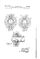
- FIGURES 5, 6 and 7 illustrate several views of a form of mounting and adjusting structure for the magnet pairs 21a, 2lb and 23a, 23h, which structure has been found to be quite satisfactory for achieving the desired blue lateral adjustment in a-ccordance with t-he principles of the invention discussed above.
- the illustrated mounting and adjusting struct-ure is the suibject of a copending application of John M. Ammerman, Serial No. 361,951 filed concurrently herewith.
- FIGURE 5 is an end view of the lateral magnet holder structure (partially in section) in position encircling the kinescope neck (shown in cross-sectional view), with the magnets midway in their range of positional adjustment.
- FIGURE 6 is a similar view, with the magnets altered from their midway position of FIGURE 5 to a position approaching the close-in end of t-he adjustment range.
- FIGURE 7 is a side view of the kinescope neck, with the lateral magnet holder structure shown in cross-section.
- the holder structure of FIGURES 5, 6 and 7 includes a main cylindrical support member 40 which is adapted to encircle the kinescope neck 11 to provide an outer cylindrical surface eccentrically related to the cylindrical neck.
- a generally crescent-shaped Weib or diaphragm member 42 extending within the cylindrical body of member 40 abuts a major portion of the outer surface of the kinescope neck, establishing the eccentricity of the outer cylindrical surface.
- Proper orientation of this web member 42 with respect to the circumference of the tube neck shifts the axis of the cylindrical surface of member 40 in a downward vertical direction relative to the tube neck axis.
- the support member 40 is provided at one end with ⁇ a raised cylindrical fiange 4l, and at the opposite end with a trio of fingerlike extensions 44 which extend longitudinally with respect to the tube axis from one end of the main cylindrical body of the support. These fingers abut the outer surface of the kinescope neck, and receive a clamping strap 46, which encircles the tube neck in abutment with the outer surface of the fingers 44.
- the strap 46 is provided with suitable means (not illustrated) for tightly securing the strap to lock the support member 46 in position on the tube neck.
- a generally cylindrical guide member 50 Surrounding the main cylindrical portion of supporty member 40 is a generally cylindrical guide member 50. Integral with the main cylindrical portion of the guide member 5f? are two raised cage members 52a, 5211 attached to the periphery of the cylindrical portion in positions apart. Each of the cagemembers 52a and 52h have respective slots 54 extending longitudinally in the center of each cage side member, the slots thus extending at right angles to the longitudinal axis of the tube neck 11. The two slots of each cage member are in registry with each other, and are adapted to receive respective end flanges 56 of a magnet holder S8.
- Each magnet holder 58 incorporates a pair of oppositely, inwardly canted magnet receiving grooves, within which are secured (eg, with glue) individual permanent ,magnets
- the Igrooves of the magnet holder 58 associated with the cage 52a are shown as receiving the individual bar magnets 21a and 2lb, whereas the grooves of the holder 58 associated with cage 52rbare 'shown as receiving the individual bar magnets 23a and 23h.
- the individual magnets are polarized as in the showing of FIGURE 2; thus, the poling of the top pair of bar magnets Zia and 2lb is such that the respective south poles thereof adjoin, whereas the poling of the bottom bar pair 23a and 23th is such that the north poles thereof adjoin.
- the main cylindrical Ibody of the support :member 40 is provided with a pair of slots 62 at its fian-ged end.
- the lugs 6ft are intended for releasable detention in the slots 62, whereby the vguide 50 is alterable between two rotational positions about the support member 4f).
- the cage 52a retaining the holder for the south pole-adjoining Ipair of magnets, is positioned at the top of the structure (i.e., in that position permitting close :approach of the magnets to the kinescope envelope) while the cage 52b is positioned at the bottom of the structure, more remote from the tube envelope due to the intenpositio-n of web member 42.
- the respective cages are reversed, with the cage 52th, retaining the holder of the north poleadjoining magnets, being located at the top of the structure, permitting close approach of this -ma-gnet pair to the tulbe envelope.
- a rotalble, disc-like cam member '70 Surrounding the periphery of the cylindrical body portion of guide Sti", to the rear of the cage locations (as viewed in FIGURES 5 and 6), is :a rotalble, disc-like cam member '70.
- the surface lof the cam member 7d adjacent to the cage location is provided with a pair of interleave-d spiral grooves 72a and 72b.
- Each of the lmagnet holders 58 is provided with a pair of rearwardly projecting pins 59. The pins of the holder retained by cage 52a ride in the spiral groove 72a, while the pins of the holder retained Iby the cage 52h ride in the groove 72b.
- the spiral 'grooves of the cam serve to impart vertical motion t-o the respective holders 58.
- the respective ⁇ grooves 72a and 72b are interleaved in such manner as to cause upward motion' of the holder in cage 52b when the Iholder in cage 52a receives downward motion, and vice versa.
- the engagement of iianlges 56 wi-th slots 54 provide :guiding action restricting the holder to motion in a vertical direction, land retaining the holder pins in the respective grooves of cam 70.
- the guide member 50 is conveniently provided with several turned up detect projections 76 abo-ut the periphery 'of its reanmost edge to act as stops for the rear surface of the cam member 70.
- the main cylindrical body portion of support' member 40 is provided with radially outwardly projecting detents (not shown) at the rear edge thereof to serve as stops for the rear edge of the cylindrical body of guide 50'.
- the iingerlike projections 44 at the rear ⁇ of support member 4) are made suificiently long so as to provide sufficient space along the ⁇ tube axis between the strap 46 location and the rear wall of the 'web member 42 to accommodate the purity correcting ring structure 80.
- the purity rings rotate about a bearing surface provided by the finger-s 44; the
- strap member 46 and the rear wall of web member 4t2 also serve to iix the location of the purity rin-g structure 80 longitudinally with respect to the tube neck 11.
- :beam position adjusting apparatus comprising:
- the lmagnets of said second pair being disposed at second selected positions spaced about the external periphery of said neck portion, the peripheral neck region adjacent to said second magnet positions being diametrically opposed to the peripheral neck re-gion adjacent to said first magnet positions;
- beam position adjusting apparatus comprising:
- the magnets of said second pair being disposed iat second selected positions spaced about the external periphery of said neck portion, the peripheral neck region adjacent to said second magnet positions being diametrically opposed to the peripheral neck region adjacent to said first magnet positions;
- beam position adjusting apparatus comprising:
- the magnets of said second pair being disposed at second selected positions spaced about the external periphery of said neck portion, the peripheral neck region adjacent to said second magnet positions being diametrically opposed to the peripheral neck region adjacent to said first magnet positions;
- an adjustable support for said magnet pairs comprising means for conjointly altering, in the same sense, the proximity of said first and second magnet pairs to the central axis of said cylindrical neck portion while maintaining a given difference in the respective proximities thereto.
- beam position adjusting apparatus comprising:
- a first pair of magnets said rst magnet pair occupy- .ing a selectable one of a tirs-t and a second set of peripherally spaced magnet locations disposed about the external periphery of said cylindrical tube neck portion;
- beam position adjusting apparatus comprising:
- first pair of magnets said first magnet pair occupying a selectable one of a first and a second set of peripherally spaced magnet locations positioned about the external periphery of said cylindrical tube neck portion, the magnets of said first pair being disposed in the selected locations with mutually adjacent north poles;
- said second magnet pair occupying the remaining one of said first and second sets of magnet locations, the peripheral neck region adjacent to said remaining set of magnet locations being diametrically opposed to the peripheral neck region adjacent to said one set of magnet locations, and the magnets of said second pair being disposed in said remaining locations with mutually adjacent south poles;
- an adjustable support for said magnet pairs comprising means for establishing a difference between the proximity to the central axis of said cylindrical neck portion of the magnet pair occuping said one set of loca-tions and the proximity to said axis of the magnet pair occuping said remaining set of locations, and means for conjointly altering, in the same sense, the proximity of both of said magnet pairs to said axis while maintaining said proximity difference.
- beam position adjusting apparatus comprising:
- first pair of magnets said first magnet pair occupying a selectable one of a rst and a second set of peripherally spaced magnet locations positioned about the external periphery of said cylindrical tube neck portion, the magnets of said first pair being disposed in the selected locations with corresponding poles of a first polarity lying adjacent to each other;
- a second pair of magnets said second magnet pair occupying the remaining one of said first and second sets of magnet locations in such a manner that the magnets of said second pair have corresponding poles of a ⁇ sec-ond polarity opposite to said first polarity lying adjacent to each other, the peripheral neck region adjacent to said remaining set of magnet locations being diametrically opposed to the peripheral neck region adjacent to said one set of magnet locations, one of said peripheral neck regions being relatively close to the enclosed path of a given one of said trio of beams and relatively remote from the enclosed paths of both of the remaining ones of said trio of beams;
- a color image reproducing tube having a generally cylindrical neck portion enclosing the paths of a trio of electron beams, said beam paths being generally parallel to the central axis of said cylindrical neck portion but substantially equally spaced therefrom in respec-tive radial directions, with a given 4one of said beam paths being spaced from said axis in a radical direction that is vertically disposed;
- apparatus for adjusting the relative positions of said beam paths in a lateral direction comprising the combination of:
- first pair of magnets said first magnet pair occupying a selectable one of a first and a second set of peripherally spaced magnet locations positioned about the external periphery of said cylindrical tube neck portion, the magnets 4of said first pair being disposed in the selected locations with corresponding poles of a first polarity lying adjacent to each other;
- said second magnet pair occupying the remaining one of said first and second sets of magnet locations in such a manner that the magnets of said second pair :have corresponding poles of a second polarity opposite to said rst polarity lying adjacent to each other, the peripheral neck l region adjacent to said remaining set of magnet locations being diametrically opposed to the peripheral neck region adjacent to said one set of magnet locations, one of said peripheral neck regions being relatively close to said given one of said beam paths and relatively remote from the remaining ones of Ibeam paths;
- a kinescope adjunct for mounting on a cylindrical kinescope neck comprising:
- a support having a cylindrical opening adapted to receive a kinescope neck
Landscapes
- Video Image Reproduction Devices For Color Tv Systems (AREA)
- Basic Packing Technique (AREA)
- Manufacture Of Electron Tubes, Discharge Lamp Vessels, Lead-In Wires, And The Like (AREA)
Priority Applications (8)
| Application Number | Priority Date | Filing Date | Title |
|---|---|---|---|
| US362092A US3290532A (en) | 1964-04-23 | 1964-04-23 | Conjointly-movable, plural magnet means for blue lateral correction in color kinescopes |
| FR13778A FR1430002A (fr) | 1964-04-23 | 1965-04-20 | Dispositif pour régler les faisceaux d'un appareil de restitution d'images en couleurs |
| GB16886/65A GB1078986A (en) | 1964-04-23 | 1965-04-21 | Magnetic electron beam control in image reproducing devices |
| BE662824A BE662824A (de) | 1964-04-23 | 1965-04-21 | |
| ES0312059A ES312059A1 (es) | 1964-04-23 | 1965-04-21 | Un aparato para regular la posicion de haz en un tubo reproductor de imagenes. |
| DER40439A DE1289869B (de) | 1964-04-23 | 1965-04-22 | Statische Strahlkonvergenzeinrichtung zum Einjustieren der Elektronenstrahlen einer Farbbildroehre |
| NL656505112A NL147278B (nl) | 1964-04-23 | 1965-04-22 | Statische bundelconvergentie-inrichting. |
| SE5340/65A SE307379B (de) | 1964-04-23 | 1965-04-23 |
Applications Claiming Priority (1)
| Application Number | Priority Date | Filing Date | Title |
|---|---|---|---|
| US362092A US3290532A (en) | 1964-04-23 | 1964-04-23 | Conjointly-movable, plural magnet means for blue lateral correction in color kinescopes |
Publications (1)
| Publication Number | Publication Date |
|---|---|
| US3290532A true US3290532A (en) | 1966-12-06 |
Family
ID=23424669
Family Applications (1)
| Application Number | Title | Priority Date | Filing Date |
|---|---|---|---|
| US362092A Expired - Lifetime US3290532A (en) | 1964-04-23 | 1964-04-23 | Conjointly-movable, plural magnet means for blue lateral correction in color kinescopes |
Country Status (7)
| Country | Link |
|---|---|
| US (1) | US3290532A (de) |
| BE (1) | BE662824A (de) |
| DE (1) | DE1289869B (de) |
| ES (1) | ES312059A1 (de) |
| GB (1) | GB1078986A (de) |
| NL (1) | NL147278B (de) |
| SE (1) | SE307379B (de) |
Cited By (12)
| Publication number | Priority date | Publication date | Assignee | Title |
|---|---|---|---|---|
| US3533031A (en) * | 1967-07-05 | 1970-10-06 | Denki Onkyo Co Ltd | Blue beam correcting devices for color television receiving tubes |
| US3646669A (en) * | 1969-12-10 | 1972-03-07 | Illinois Tool Works | Method of making blue lateral and purity magnets |
| US3701065A (en) * | 1971-02-03 | 1972-10-24 | Rca Corp | Color picture tube beam convergence apparatus |
| US3743985A (en) * | 1971-06-18 | 1973-07-03 | Matsushita Electric Industrial Co Ltd | Convergence system |
| US3873953A (en) * | 1974-02-14 | 1975-03-25 | Gte Sylvania Inc | Magnet retaining means for a CRT beam adjustment device |
| US3887833A (en) * | 1969-06-16 | 1975-06-03 | Hitachi Ltd | Color purity adjusting device for a color picture tube |
| US4030126A (en) * | 1976-01-16 | 1977-06-14 | Gte Sylvania Incorporated | Support means for a CRT beam adjustment device |
| FR2356267A1 (fr) * | 1976-06-21 | 1978-01-20 | Rca Corp | Dispositif de convergence excentrique pour un tube a rayons cathodiques a faisceaux en ligne |
| FR2389225A1 (fr) * | 1977-04-25 | 1978-11-24 | Rca Corp | Dispositif de convergence statique comportant un correcteur magnetique |
| US4232283A (en) * | 1979-03-27 | 1980-11-04 | Rca Corporation | Electron beam moving apparatus for a color cathode ray tube |
| US4245205A (en) * | 1979-02-14 | 1981-01-13 | Rca Corporation | Convergence adjustment arrangement using magnetic tabs with differential motion and rotary drive |
| US4489993A (en) * | 1981-06-17 | 1984-12-25 | Hitachi, Ltd. | CRT mounting structure |
Families Citing this family (1)
| Publication number | Priority date | Publication date | Assignee | Title |
|---|---|---|---|---|
| US4253077A (en) * | 1979-10-30 | 1981-02-24 | Rca Corporation | Yoke tabbing device |
Family Cites Families (2)
| Publication number | Priority date | Publication date | Assignee | Title |
|---|---|---|---|---|
| US2950407A (en) * | 1956-12-21 | 1960-08-23 | Rca Corp | Electric beam controlling apparatus |
| US3302049A (en) * | 1963-05-03 | 1967-01-31 | Rca Corp | Magnet means for correction of blue beam lateral deflection for color television receiver tubes |
-
1964
- 1964-04-23 US US362092A patent/US3290532A/en not_active Expired - Lifetime
-
1965
- 1965-04-21 GB GB16886/65A patent/GB1078986A/en not_active Expired
- 1965-04-21 BE BE662824A patent/BE662824A/xx unknown
- 1965-04-21 ES ES0312059A patent/ES312059A1/es not_active Expired
- 1965-04-22 DE DER40439A patent/DE1289869B/de not_active Withdrawn
- 1965-04-22 NL NL656505112A patent/NL147278B/xx unknown
- 1965-04-23 SE SE5340/65A patent/SE307379B/xx unknown
Non-Patent Citations (1)
| Title |
|---|
| None * |
Cited By (13)
| Publication number | Priority date | Publication date | Assignee | Title |
|---|---|---|---|---|
| US3533031A (en) * | 1967-07-05 | 1970-10-06 | Denki Onkyo Co Ltd | Blue beam correcting devices for color television receiving tubes |
| US3887833A (en) * | 1969-06-16 | 1975-06-03 | Hitachi Ltd | Color purity adjusting device for a color picture tube |
| US3646669A (en) * | 1969-12-10 | 1972-03-07 | Illinois Tool Works | Method of making blue lateral and purity magnets |
| US3701065A (en) * | 1971-02-03 | 1972-10-24 | Rca Corp | Color picture tube beam convergence apparatus |
| US3743985A (en) * | 1971-06-18 | 1973-07-03 | Matsushita Electric Industrial Co Ltd | Convergence system |
| US3873953A (en) * | 1974-02-14 | 1975-03-25 | Gte Sylvania Inc | Magnet retaining means for a CRT beam adjustment device |
| US4030126A (en) * | 1976-01-16 | 1977-06-14 | Gte Sylvania Incorporated | Support means for a CRT beam adjustment device |
| FR2356267A1 (fr) * | 1976-06-21 | 1978-01-20 | Rca Corp | Dispositif de convergence excentrique pour un tube a rayons cathodiques a faisceaux en ligne |
| US4100518A (en) * | 1976-06-21 | 1978-07-11 | Rca Corporation | Eccentric convergence apparatus for in-line beam cathode ray tubes |
| FR2389225A1 (fr) * | 1977-04-25 | 1978-11-24 | Rca Corp | Dispositif de convergence statique comportant un correcteur magnetique |
| US4245205A (en) * | 1979-02-14 | 1981-01-13 | Rca Corporation | Convergence adjustment arrangement using magnetic tabs with differential motion and rotary drive |
| US4232283A (en) * | 1979-03-27 | 1980-11-04 | Rca Corporation | Electron beam moving apparatus for a color cathode ray tube |
| US4489993A (en) * | 1981-06-17 | 1984-12-25 | Hitachi, Ltd. | CRT mounting structure |
Also Published As
| Publication number | Publication date |
|---|---|
| NL6505112A (de) | 1965-10-25 |
| GB1078986A (en) | 1967-08-09 |
| SE307379B (de) | 1969-01-07 |
| DE1289869B (de) | 1969-02-27 |
| BE662824A (de) | 1965-08-17 |
| ES312059A1 (es) | 1965-07-01 |
| NL147278B (nl) | 1975-09-15 |
Similar Documents
| Publication | Publication Date | Title |
|---|---|---|
| US3290532A (en) | Conjointly-movable, plural magnet means for blue lateral correction in color kinescopes | |
| US3930185A (en) | Display system with simplified convergence | |
| EP0456942B1 (de) | Ablenkjoch mit überlappenden Ablenkspulen | |
| US3290533A (en) | Conjointly-movable cam-actuated support means for magnets in color kinescopes | |
| US2255039A (en) | Cathode ray deflecting device | |
| US2816244A (en) | Electron beam controlling apparatus | |
| US2923844A (en) | Cathode ray tube structure including convergence system | |
| NO782440L (no) | Magnetiseringsanordning og fremgangsmaate til anvendelse av denne ved korrigering av fargeenheten i et katodestraaleroer | |
| US3375389A (en) | Adjustable convergence magnets | |
| CA1093625A (en) | Apparatus producing static eight-pole magnetic field for correcting raster distortion in a television picture tube | |
| US3898597A (en) | Pairs of oppositely rotatable ring magnets for a color television display device | |
| US3622835A (en) | Current-generating circuit | |
| US3873877A (en) | Mislanding corrector for color cathode ray tubes | |
| US3290534A (en) | Eccentrically mounted beam position adjusting device | |
| US4198614A (en) | Deflection yoke assembly including a beam positioning magnet arrangement | |
| US3906418A (en) | Means for effecting dynamic vertical convergence in an in-line plural beam cathode ray tube | |
| US3789258A (en) | Electron beam and deflection yoke alignment for producing convergence of plural in-line beams | |
| US3098942A (en) | Magnetic centering device for cathode ray tubes | |
| Barbin et al. | New color picture tube system for portable TV receivers | |
| US3356879A (en) | Beam positioning device for varying the effective origin of cathode-ray tube electron beam | |
| US3717788A (en) | Cathode ray tube arrangement utilizing magnetic shunts for controlling color registration | |
| US3631296A (en) | Television deflection system | |
| US2859365A (en) | Electron beam controlling apparatus | |
| US2880367A (en) | Cathode ray tube apparatus | |
| US2880366A (en) | Cathode ray beam control apparatus |