US3269419A - Fluid amplifiers - Google Patents
Fluid amplifiers Download PDFInfo
- Publication number
- US3269419A US3269419A US284996A US28499663A US3269419A US 3269419 A US3269419 A US 3269419A US 284996 A US284996 A US 284996A US 28499663 A US28499663 A US 28499663A US 3269419 A US3269419 A US 3269419A
- Authority
- US
- United States
- Prior art keywords
- jet
- fluid
- laminar
- passage
- side wall
- Prior art date
- Legal status (The legal status is an assumption and is not a legal conclusion. Google has not performed a legal analysis and makes no representation as to the accuracy of the status listed.)
- Expired - Lifetime
Links
Images

Classifications
-
- F—MECHANICAL ENGINEERING; LIGHTING; HEATING; WEAPONS; BLASTING
- F15—FLUID-PRESSURE ACTUATORS; HYDRAULICS OR PNEUMATICS IN GENERAL
- F15C—FLUID-CIRCUIT ELEMENTS PREDOMINANTLY USED FOR COMPUTING OR CONTROL PURPOSES
- F15C1/00—Circuit elements having no moving parts
- F15C1/02—Details, e.g. special constructional devices for circuits with fluid elements, such as resistances, capacitive circuit elements; devices preventing reaction coupling in composite elements ; Switch boards; Programme devices
- F15C1/04—Means for controlling fluid streams to fluid devices, e.g. by electric signals or other signals, no mixing taking place between the signal and the flow to be controlled
-
- Y—GENERAL TAGGING OF NEW TECHNOLOGICAL DEVELOPMENTS; GENERAL TAGGING OF CROSS-SECTIONAL TECHNOLOGIES SPANNING OVER SEVERAL SECTIONS OF THE IPC; TECHNICAL SUBJECTS COVERED BY FORMER USPC CROSS-REFERENCE ART COLLECTIONS [XRACs] AND DIGESTS
- Y10—TECHNICAL SUBJECTS COVERED BY FORMER USPC
- Y10T—TECHNICAL SUBJECTS COVERED BY FORMER US CLASSIFICATION
- Y10T137/00—Fluid handling
- Y10T137/206—Flow affected by fluid contact, energy field or coanda effect [e.g., pure fluid device or system]
- Y10T137/218—Means to regulate or vary operation of device
- Y10T137/2202—By movable element
- Y10T137/2207—Operating at timed intervals [e.g., to produce pulses]
-
- Y—GENERAL TAGGING OF NEW TECHNOLOGICAL DEVELOPMENTS; GENERAL TAGGING OF CROSS-SECTIONAL TECHNOLOGIES SPANNING OVER SEVERAL SECTIONS OF THE IPC; TECHNICAL SUBJECTS COVERED BY FORMER USPC CROSS-REFERENCE ART COLLECTIONS [XRACs] AND DIGESTS
- Y10—TECHNICAL SUBJECTS COVERED BY FORMER USPC
- Y10T—TECHNICAL SUBJECTS COVERED BY FORMER US CLASSIFICATION
- Y10T137/00—Fluid handling
- Y10T137/206—Flow affected by fluid contact, energy field or coanda effect [e.g., pure fluid device or system]
- Y10T137/218—Means to regulate or vary operation of device
- Y10T137/2202—By movable element
- Y10T137/2213—Electrically-actuated element [e.g., electro-mechanical transducer]
-
- Y—GENERAL TAGGING OF NEW TECHNOLOGICAL DEVELOPMENTS; GENERAL TAGGING OF CROSS-SECTIONAL TECHNOLOGIES SPANNING OVER SEVERAL SECTIONS OF THE IPC; TECHNICAL SUBJECTS COVERED BY FORMER USPC CROSS-REFERENCE ART COLLECTIONS [XRACs] AND DIGESTS
- Y10—TECHNICAL SUBJECTS COVERED BY FORMER USPC
- Y10T—TECHNICAL SUBJECTS COVERED BY FORMER US CLASSIFICATION
- Y10T137/00—Fluid handling
- Y10T137/206—Flow affected by fluid contact, energy field or coanda effect [e.g., pure fluid device or system]
- Y10T137/2273—Device including linearly-aligned power stream emitter and power stream collector
Definitions
- FLUID AMPLIFIERS Filed June 5, 1965 2 Sheets-Sheet 2 INVENTOR. EDWIN M. DEXTER ATTORNEY 4 3,259,419 Ice Patented August 30, 3966 3,269,419 FLUID AMPLEFEERS Edwin M. Dexter, Silver Spring, Md assignor to General Electric Company, a corporation of New York Filed June 3, 1963, Ser. No. 284,996
- This invention relates to fluid control devices and more particularly, to digital type fluid amplifiers.
- Fluid amplifiers have the potential for wide application in various fields, due primarily to their reliability, temperature insensitivity, shock resistance, and ease of fabrication. These devices may be employed as digital computing elements and also as power devices to operate valves and the like. Fluid amplifiers may be operated as pneumatic devices employing a compressible fluid, such as gas or air, or as hydraulic devices utilizing an incompressible fluid, such as water or oil.-
- One of the basic types of fluid amplifier is the boundary layer effect type.
- power jet deflection is efiected by the side walls of an interaction chamber shaped in such a way that the power jet attaches to one or the other of the side walls but not to both side walls.
- This is brought about, after initial lateral deflection by a control jet, by the entrainment action of the power jet, wherein the power jet, comprising turbulent air, tends to entrain air at a lower pressure between it and an adjacent side wall.
- the entrainment becomes more effective as the power jet approaches more closely to the adjacent side wall, since the pressure of the trapped air becomes still lower.
- the jet becomes stable in the attached position to the wall.
- This type of amplifier is basically a two position device, and for this reason is generally referred to as a digital device.
- the binary fluid amplifier of the prior art therefore requires the use of one or more control fluid jets to obtain the digital switching action.
- a fluid amplifier wherein the power jet is ordinarily maintained at a pressure level providing laminar flow. Further, the boundary layer of the laminar power jet is ordinarily sufliciently close to a side wall such that if turbulent flow existed, the power jet would start switching toward the side wall and latch on thereto, but is not so close as to entrain with laminar flow. Switching, i.e., power jet deflection from one output port to another, is accomplished by converting the laminar power jet into a turbulent power jet. When the turbulence is created, the power jet commences deflecting toward the more closely spaced adjacent side wall and entrainment between the turbulent jet and the side wall is created. This deflected turbulent jet now remains latched against that side wall until such time as laminar power jet flow is restored.
- turbulent flow is obtained by a piezoelectric crystal disposed in the side wall closely adjacent the power jet nozzle and therefore closely adjacent the jet boundary layer.
- the opposite side wall is farther removed from the jet, i.e., the two side walls are asymmetrically disposed relative to the laminar power jet.
- Rapid oscillation of the piezoelectric crystal by means of an A.C. source results in rapid movement or oscillation of the side wall whereby the laminar power jet is disrupted sulficiently to result in turbulence.
- This turbulent jet switches to the closer side wall and latches. Cutting ofl the motion of the piezoelectric crystal eliminates the forces tending to create the turbulence, and laminar flow is restored. The power jet then switches back to its other binary state.
- the device may be elfectively utilized as a monostable flip-flop in that its ordinary state of deflection is directed toward one output port whenever it is in the condition of laminar flow; it switches to another state of deflection directed to another output port only during the application of an AC. signal to the turbulence generating switching means. As soon as the signal is removed, the device switches back to its stable deflected state due to the return to laminar flow.
- a device in accordance with the principles of the invention may also be applied as an electrical-to-pneumatic control transducer.
- information may be borne by trains of AC. pulse signals, which ultimately are to be utilized in a fluid control system, the application of the AC. pulses to a device in accordance with the principles of the invention, effectively transforms each electrical pulse into a change of state in the pneumatic device.
- the invention contemplates a fluid control transducer with any form of energy inputs thereto, e.g., electrical, thermal, acoustic or mechanical.
- One of the features of the invention resides in the fact that there are no fluid control jets needed nor utilized in the constnuction of the device.
- FIG. 1 is a perspective, partially cut-away view of a fluid amplifier embodiment of the invention
- FIG. 1A is a schematic view of the electro-mechanical transducer circuit used in the embodiment of FIG. 1;
- FIGS. 2 and 3 are fluid amplifier embodiments of the invention having variant geometries.
- FIG. 1 an embodiment of the invention, given by way of example, of a mono-stable digital type fluid amplifier wherein the switching mechanism comprises a piezoelectric crystal.
- the device is diagrammatically shown in FIG. 1 as including a. plate 11, formed of suitable material, such as metal, plastic or the like, which is slotted in a special configuration to provide passages for fluid.
- the various slots in plate 11 may be formed in any suitable manner and may extend entirely through the plate or be made of lesser depth, as desired. In the illustrated embodiment, the slots in plate 1'1 are shown extending only partially therethrough.
- the plate includes a main opening 12 into which extends a conduit or passage 13 which carries the pressurized fluid into the opening 12, it being understood that a suitable enclosure, such as covering plate 9, is positioned on the top side of plate 11 to confine fluid to the various slots of plate 11.
- the fluid utilized in the control device may assume a variety of forms.
- the fluid may constitute a compressible fluid, such as air, to provide a pneumatic device.
- the fluid may be incompressible, such as oil or water, to provide a hydraulic device.
- a restricted slot 14 constituting a nozzle from which issues a power jet of fluid emanating from conduit 13.
- a power jet of fluid emanating from conduit 13
- two fluid receivers in the form of diverging channels or passages 22 and 24.
- the outputs of channels 22 and 24 may be applied to any type of utilizing means for actuation either by fluid flow or fluid pressure under the control of which one of passages 22 and 24 has the output.
- Channel 24 is axially aligned with the nozzle 14.
- the power jet fluid may be supplied to opening 12 through conduit 13 by an appropriate constant supply low pressure source, e.g., a fiberglass impeller blower (not shown).
- the axis of channel 22 is angularly displaced from the axis of nozzle 14.
- the side wall 16 adjoining the left hand side of nozzle 14 to the left hand side of channel 22 forms an acute angle when extended to intersect the axis of nozzle 14.
- Wall 16 curves away from nozzle 14 sufficiently to preclude entrainment when the power jet is laminar but close enough for entrainment when the flow is turbulent.
- Disposed in side wall 16 at the point where nozzle 14 opens into interaction chamber 17 is one face 18 of a piezo-electric crystal 19.
- Two electrical leads 25 and 26 disposed on opposite sides of crystal 19 are connected to an electrical circuit 20 capable of applying alternating current signals to crystal 19.
- the side wall 28 on the opposite side of nozzle 14 from crystal 19 curves smoothly but radically away from the axis of nozzle 14 to ultimately curve back, after forming a Wide concave path, to meet the right hand Wall of the channel 24.
- the pneumatic power jet is applied to nozzle 14 at a low supply pressure, which may be approximately two pounds per square inch or less to insure laminar flow of the power jet as it passes from nozzle 14 into the interaction chamber 17. It is characteristic of laminar flow that the boundary layer of the fluid jet remains substantially parallel or non-divergent for distances equal to many times the diameter of the nozzle from whence it issues. Accordingly, without anything more, the laminar power jet issuing from nozzle 14 passes directly and linearly to and through channel 24. Passage of fluid to channel 24 constitutes the stable state for this embodiment.
- the divergence brings the boundary layer of the now turbulent power jet closer to side wall 16, whereupon entrainment action commences between the power jet and side wall 16.
- Side wall 16 is sufliciently close so that latching of the power jet to the left hand side wall occurs quite rapidly.
- the turbulence of the power jet has no effect on the right hand side of the device, since side wall 28 swings sharply and radically away from the path of the jet, even when the boundary layer of the jet diverges due to turbulence. Under these circumstances, then, the turbulent jet remains latched to left hand side 16 and the power jet is directed to the left hand fluid output channel 22. When osgillation of the crystal 19 ceases, as when the AC.
- the device of FIG. 1 is such that the power jet deflection follows the electrical signal input to the crystal.
- a pulse train (each pulse of which constitutes at least several cycles of an AC. signal) applied to crystal 19 results in the power jet oscillating back and forth between channels 22 and 24 at the same frequency as the pulse repetition rate of the input electrical signal.
- Periodic operation of course, is not necessaryry; monostable flip-flop action is provided with any type of pulsing.
- the electrical circuit controlling the piezo-electric crystal 19 may be of the type known in the art as shown in FIG. 1A.
- piezo-electric crystal 19 is shown with two side metallic plates 30 and 31 to which are secured electrical leads 25 and 26, respectively.
- Crystal 19, which may be of quartz, generates a mechanical force causing expansion and contraction of the faces 18 and 18 of crystal 19 when an AC. voltage is applied across plates 30 and 3-1. This is the well known inverse piezo-electric effect.
- the quartz crystal 19 has a natural frequency of expansion and contraction.
- the circuit of FIG. 1A has an A.C. frequency source for generating the natural frequency of the crystal and applying it thereto through transformer 34 with a variable capacitor 3 6 in parallel with crystal 19.
- a magnetostrictive device may be disposed in the wall in lieu of crystal 19.
- Appropriate control circuits for operating the magneto-strictive device produce similar effects.
- the device may be utilized as a temperature control device by utilizing a bimetallic temperature sensitive element having one face positioned to protrude from the side wall region. When the temperature is suflicient to cause movement of the temperature sensitive bimetallic device, the element is caused to protrude into the fluid path, causing a physical disruption sufficient to create turbulence.
- Acoustical vibrations from an oscillating membrane may be used to generate condensations and rarefactions in the air adjacent the laminar jet to cause the desired switching.
- An audio oscillator arrangement controlling a pneumatic jet is shown, for example, in United States Letters Patent Nos. 1,477,645 and 1,549,196.
- FIG. 2 there is presented a fluid amplifier which is basically similar to the embodiment of FIG. 1 but with certain modifications, any one of which, or all, may be incorporated in the structure of FIG. 1.
- One of the features of difference between the two embodiments is the vents 41 and 42 of FIG. 2, shown as opening through the side walls immediately adjacent receiver channels 22' and 24, respectively.
- the downstream ends of vents 41 and 42 open to the ambient atmosphere. It has been found that venting arrangements of this type improve the operation of a fluid amplifier, and a detailed description of the value and function of such venting arrangements is presented in United States patent application, Serial No. 236,- 777, entitled Fluid Control Devices filed November 8, 1962, by Willis A. Boothe, now Patent No. 3,181,546.
- the piezo-electric crystal 49 is in all respects similar to crystal 19 and is controlled by a circuit of the type of FIG. 1A; however, is located in a different place from its counterpart in FIG. 1.
- the piezo-electric crystal 49 is disposed upstream of the location of the crystal in FIG. 1. More particularly, crystal 49 is shown as being located midway along the wall of the nozzle passage 14. Another appropriate location is even far- 5 ther upstream in the wall of the opening 12 located upstream of the entire nozzle passage 14" (as shown by the broken line representation 49').
- the 49 and 49' crystal locations may more readily produce turbulence in the jet emerging from nozzle 14 than would the crystal location 19 of FIG. 1.
- FIG. 2 The last feature of FIG. 2 which is different from that of FIG. 1 is the elongated inlet 12 of FIG. 2 with the incorporation therein of fluid flow straighteners 51, the combination of which is designed to reduce inlet turbulence.
- Inlet 12 has a much longer axial'length in the direction of fluid flow than does inlet 12 of FIG. 1. A longer path for the fluid to travel is insured by locating the inlet passage 13 at the end of opening 12 remote from nozzle 14'.
- the flow straighteners 51 are a parallel array of thin vanes disposed approximately midway between passage 13' and nozzle 14', through which the power jet must pass. The elongated path and the vanes serve to reduce undesired turbulence in the inlet portion of the fluid amplifier.
- FIG. 3 is a fluid amplifier substantially as shown in FIG. 2 but with a different venting arrangement. Vents 55 and 56 of FIG. 3 are disposed adjacent the nozzle 14 rather than farther downstream adjacent the fluid channels 22 and 24 as is the case in FIG. 2. Furthermore, vent 55 on the lefthand side adjacent wall 16" is much narrower than vent 56 on the opposite side of nozzle 14". The difference in the widths of the vents has to do with precluding the generation of turbulence of a self-induced nature and therefore with the reduction of turbulence when it is not desired.
- the vent 55 constitutes a capillary type resistance, and when the power jet is substantially in laminar flow the resistance is not very large with respect to the low level laminar entrainment requirements, i.e.
- venting performed by vent 55 is effective.
- the capillary resistance of vent 5 5 is quite large and in fact provides a sufliciently large resistance with respect to turbulent requirements such that the power jet attaches to wall 16" when turbulence in the power jet pre vails.
- a fluid amplifier comprising: means for generating a laminar fluid power jet including a passage from whence said jet issues; first and second fluid receivers spaced from said passage, said first fluid receiver being axially aligned with said passage and said second receiver angularly displaced from the axis of said passage; said fluid amplifier having a side wall on each of two opposite sides of said laminar jet with one of said side walls spaced more closely to the axis of said passage than the other; and means disposed in said one of said side walls for changing the laminar flow of said jet to turbulent flow so that the jet latches to said one of said side walls when the jet is turbulent and does not latch when the jet is laminar, thereby causing the jet to flow to said first receiver when said jet is laminar and causing the jet to flow to said second receiver when said jet is turbulent.
- a fluid amplifier as recited in claim 1 in which said means in said one of said side walls is a piezoelectric crystal having one face thereof form part of said side wall, and an electrical circuit for applying an AC, signal to two opposite faces of said crystal other than said one face.
- a fluid amplifier comprising: means for generating a laminar fluid power jet including a passage from whence said jet issues, said laminar jet following substantially a straight line path; and nonfluid means disposed closely adjacent said passage for changing the laminar flow of said jet to turbulent flow; said amplifier having side walls on opposite sides of the path followed by said laminar jet issuing from said passage, said side walls being asymmetrically disposed relative to said jet path with one of said side walls spaced closer to the straight line path of the laminar jet than the other such that said jet latches to said one of said walls only when said jet is turbulent and remains unlatched when said jet is laminar.
Landscapes
- Engineering & Computer Science (AREA)
- General Engineering & Computer Science (AREA)
- Theoretical Computer Science (AREA)
- Physics & Mathematics (AREA)
- Fluid Mechanics (AREA)
- Mechanical Engineering (AREA)
- Measuring Volume Flow (AREA)
- Reciprocating Pumps (AREA)
- Special Spraying Apparatus (AREA)
Description
Filed June 5.. 1963 2 Sheets-Sheet l FIG.|
INVENTOR. EDWIN M. DEXTER ATTORNEY Aug. 30, 1966 E. M. DEXTER 3,269,419
FLUID AMPLIFIERS Filed June 5, 1965 2 Sheets-Sheet 2 INVENTOR. EDWIN M. DEXTER ATTORNEY 4 3,259,419 Ice Patented August 30, 3966 3,269,419 FLUID AMPLEFEERS Edwin M. Dexter, Silver Spring, Md assignor to General Electric Company, a corporation of New York Filed June 3, 1963, Ser. No. 284,996
3 @laims. (Cl. 1378ll.5)
This invention relates to fluid control devices and more particularly, to digital type fluid amplifiers.
Fluid amplifiers have the potential for wide application in various fields, due primarily to their reliability, temperature insensitivity, shock resistance, and ease of fabrication. These devices may be employed as digital computing elements and also as power devices to operate valves and the like. Fluid amplifiers may be operated as pneumatic devices employing a compressible fluid, such as gas or air, or as hydraulic devices utilizing an incompressible fluid, such as water or oil.-
One of the basic types of fluid amplifier is the boundary layer effect type. In this device, power jet deflection is efiected by the side walls of an interaction chamber shaped in such a way that the power jet attaches to one or the other of the side walls but not to both side walls. This is brought about, after initial lateral deflection by a control jet, by the entrainment action of the power jet, wherein the power jet, comprising turbulent air, tends to entrain air at a lower pressure between it and an adjacent side wall. The entrainment becomes more effective as the power jet approaches more closely to the adjacent side wall, since the pressure of the trapped air becomes still lower. The jet becomes stable in the attached position to the wall. This type of amplifier is basically a two position device, and for this reason is generally referred to as a digital device. The binary fluid amplifier of the prior art therefore requires the use of one or more control fluid jets to obtain the digital switching action.
In accordance with the principles of the invention, however, a different mechanism and a new basis for providing switching action has been discovered and utilized in a fluid amplifier. The entrainment action mentioned above which is responsible for providing the latching effect, i.e., the maintenance of the power jet against one of the side walls irrespective of whether the lateral control jet switching it to that side has been removed or not, occurs when the power jet fluid is turbulent. If, however, the flow is laminar, the entrainment action described above and the latching effect provided by transverse motion of the power jet due to the control jet is substantially eliminated.
In accordance with the principles of the invention, a fluid amplifier is provided wherein the power jet is ordinarily maintained at a pressure level providing laminar flow. Further, the boundary layer of the laminar power jet is ordinarily sufliciently close to a side wall such that if turbulent flow existed, the power jet would start switching toward the side wall and latch on thereto, but is not so close as to entrain with laminar flow. Switching, i.e., power jet deflection from one output port to another, is accomplished by converting the laminar power jet into a turbulent power jet. When the turbulence is created, the power jet commences deflecting toward the more closely spaced adjacent side wall and entrainment between the turbulent jet and the side wall is created. This deflected turbulent jet now remains latched against that side wall until such time as laminar power jet flow is restored.
In one embodiment in accordance with the principles of the invention, turbulent flow is obtained by a piezoelectric crystal disposed in the side wall closely adjacent the power jet nozzle and therefore closely adjacent the jet boundary layer. The opposite side wall is farther removed from the jet, i.e., the two side walls are asymmetrically disposed relative to the laminar power jet. Rapid oscillation of the piezoelectric crystal by means of an A.C. source results in rapid movement or oscillation of the side wall whereby the laminar power jet is disrupted sulficiently to result in turbulence. This turbulent jet switches to the closer side wall and latches. Cutting ofl the motion of the piezoelectric crystal eliminates the forces tending to create the turbulence, and laminar flow is restored. The power jet then switches back to its other binary state.
The device may be elfectively utilized as a monostable flip-flop in that its ordinary state of deflection is directed toward one output port whenever it is in the condition of laminar flow; it switches to another state of deflection directed to another output port only during the application of an AC. signal to the turbulence generating switching means. As soon as the signal is removed, the device switches back to its stable deflected state due to the return to laminar flow.
Aside from its application as a mono-stable fluid flipflop, a device in accordance with the principles of the invention, may also be applied as an electrical-to-pneumatic control transducer. Where information may be borne by trains of AC. pulse signals, which ultimately are to be utilized in a fluid control system, the application of the AC. pulses to a device in accordance with the principles of the invention, effectively transforms each electrical pulse into a change of state in the pneumatic device.
Many other energy forms may be used to actuate the means for generating turbulence in the previously laminar jet flow. In a general sense the invention contemplates a fluid control transducer with any form of energy inputs thereto, e.g., electrical, thermal, acoustic or mechanical.
One of the features of the invention resides in the fact that there are no fluid control jets needed nor utilized in the constnuction of the device.
The novel features believed to be characteristic of this invention are set forth with particularity in the appended claims. The invention itself, however, both as to its organization and method of operation, together with further objects and advantages thereof, may best be understood by reference to the following description taken in connection with the accompanying drawings.
In the drawings:
FIG. 1 is a perspective, partially cut-away view of a fluid amplifier embodiment of the invention;
FIG. 1A is a schematic view of the electro-mechanical transducer circuit used in the embodiment of FIG. 1; and
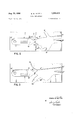
FIGS. 2 and 3 are fluid amplifier embodiments of the invention having variant geometries.
Referring now to the drawings in greater detail, there is illustrated in FIG. 1 an embodiment of the invention, given by way of example, of a mono-stable digital type fluid amplifier wherein the switching mechanism comprises a piezoelectric crystal. The device is diagrammatically shown in FIG. 1 as including a. plate 11, formed of suitable material, such as metal, plastic or the like, which is slotted in a special configuration to provide passages for fluid. The various slots in plate 11 may be formed in any suitable manner and may extend entirely through the plate or be made of lesser depth, as desired. In the illustrated embodiment, the slots in plate 1'1 are shown extending only partially therethrough. The plate includes a main opening 12 into which extends a conduit or passage 13 which carries the pressurized fluid into the opening 12, it being understood that a suitable enclosure, such as covering plate 9, is positioned on the top side of plate 11 to confine fluid to the various slots of plate 11. The fluid utilized in the control device may assume a variety of forms. For example, the fluid may constitute a compressible fluid, such as air, to provide a pneumatic device. As a further example, the fluid may be incompressible, such as oil or water, to provide a hydraulic device.
Communicating with opening 12 is a restricted slot 14, constituting a nozzle from which issues a power jet of fluid emanating from conduit 13. At a distance from the nozzle of several times the diameter of nozzle 14 are disposed two fluid receivers in the form of diverging channels or passages 22 and 24. The outputs of channels 22 and 24 may be applied to any type of utilizing means for actuation either by fluid flow or fluid pressure under the control of which one of passages 22 and 24 has the output. Channel 24 is axially aligned with the nozzle 14. The power jet fluid may be supplied to opening 12 through conduit 13 by an appropriate constant supply low pressure source, e.g., a fiberglass impeller blower (not shown).
The axis of channel 22 is angularly displaced from the axis of nozzle 14. The side wall 16 adjoining the left hand side of nozzle 14 to the left hand side of channel 22 forms an acute angle when extended to intersect the axis of nozzle 14. Wall 16 curves away from nozzle 14 sufficiently to preclude entrainment when the power jet is laminar but close enough for entrainment when the flow is turbulent. Disposed in side wall 16 at the point where nozzle 14 opens into interaction chamber 17 is one face 18 of a piezo-electric crystal 19. Two electrical leads 25 and 26 disposed on opposite sides of crystal 19 are connected to an electrical circuit 20 capable of applying alternating current signals to crystal 19. The side wall 28 on the opposite side of nozzle 14 from crystal 19 curves smoothly but radically away from the axis of nozzle 14 to ultimately curve back, after forming a Wide concave path, to meet the right hand Wall of the channel 24.
The pneumatic power jet is applied to nozzle 14 at a low supply pressure, which may be approximately two pounds per square inch or less to insure laminar flow of the power jet as it passes from nozzle 14 into the interaction chamber 17. It is characteristic of laminar flow that the boundary layer of the fluid jet remains substantially parallel or non-divergent for distances equal to many times the diameter of the nozzle from whence it issues. Accordingly, without anything more, the laminar power jet issuing from nozzle 14 passes directly and linearly to and through channel 24. Passage of fluid to channel 24 constitutes the stable state for this embodiment.
When, however, an alternating current is applied from input control circuit 20 to piezo-electric crystal 19, the electrical signal is converted into an oscillatory expansion and contraction of crystal face 18 which is characteristic of the inverse piezo-electric effect. Motion of the crystal surface constitutes actual oscillation of that portion of side wall 16 immediately adjacent the output of nozzle 14. This mechanical oscillation of crystal face 18 causes condensations and rarefactions of the air in its immediate vicinity and thereby causes a physical disruption in the boundary layer of the laminar power jet. In turn, the power jet becomes turbulent and its boundary layer diverges.
The divergence brings the boundary layer of the now turbulent power jet closer to side wall 16, whereupon entrainment action commences between the power jet and side wall 16. Side wall 16 is sufliciently close so that latching of the power jet to the left hand side wall occurs quite rapidly. The turbulence of the power jet has no effect on the right hand side of the device, since side wall 28 swings sharply and radically away from the path of the jet, even when the boundary layer of the jet diverges due to turbulence. Under these circumstances, then, the turbulent jet remains latched to left hand side 16 and the power jet is directed to the left hand fluid output channel 22. When osgillation of the crystal 19 ceases, as when the AC. signal from source 20 is removed, the rarefactions and condensations cease and turbulence is no longer maintained by the power jet and the laminar flow condition is restored. With laminar flow, the entrainment action cannot exist with the geometry of the device of FIG. 1 and the power jet switches back to its initial condition and exits from channel 24. It may be seen, therefore, that in operation, the device of FIG. 1 is such that the power jet deflection follows the electrical signal input to the crystal. Thus, a pulse train (each pulse of which constitutes at least several cycles of an AC. signal) applied to crystal 19 results in the power jet oscillating back and forth between channels 22 and 24 at the same frequency as the pulse repetition rate of the input electrical signal. Periodic operation, of course, is not necesarry; monostable flip-flop action is provided with any type of pulsing.
The electrical circuit controlling the piezo-electric crystal 19 may be of the type known in the art as shown in FIG. 1A. As shown in FIG. 1A, piezo-electric crystal 19 is shown with two side metallic plates 30 and 31 to which are secured electrical leads 25 and 26, respectively. Crystal 19, which may be of quartz, generates a mechanical force causing expansion and contraction of the faces 18 and 18 of crystal 19 when an AC. voltage is applied across plates 30 and 3-1. This is the well known inverse piezo-electric effect. The quartz crystal 19 has a natural frequency of expansion and contraction. The circuit of FIG. 1A has an A.C. frequency source for generating the natural frequency of the crystal and applying it thereto through transformer 34 with a variable capacitor 3 6 in parallel with crystal 19. In such a circuit, the mechanical motion of the system is maximized Various switching means may be utilized in accordance with the principles of the invention other than the piezoelectric crystal of FIG. 1. Thus, for example, a magnetostrictive device may be disposed in the wall in lieu of crystal 19. Appropriate control circuits for operating the magneto-strictive device produce similar effects. Alternatively, the device may be utilized as a temperature control device by utilizing a bimetallic temperature sensitive element having one face positioned to protrude from the side wall region. When the temperature is suflicient to cause movement of the temperature sensitive bimetallic device, the element is caused to protrude into the fluid path, causing a physical disruption sufficient to create turbulence. Acoustical vibrations from an oscillating membrane may be used to generate condensations and rarefactions in the air adjacent the laminar jet to cause the desired switching. An audio oscillator arrangement controlling a pneumatic jet is shown, for example, in United States Letters Patent Nos. 1,477,645 and 1,549,196.
In FIG. 2, there is presented a fluid amplifier which is basically similar to the embodiment of FIG. 1 but with certain modifications, any one of which, or all, may be incorporated in the structure of FIG. 1. One of the features of difference between the two embodiments is the vents 41 and 42 of FIG. 2, shown as opening through the side walls immediately adjacent receiver channels 22' and 24, respectively. The downstream ends of vents 41 and 42 open to the ambient atmosphere. It has been found that venting arrangements of this type improve the operation of a fluid amplifier, and a detailed description of the value and function of such venting arrangements is presented in United States patent application, Serial No. 236,- 777, entitled Fluid Control Devices filed November 8, 1962, by Willis A. Boothe, now Patent No. 3,181,546.
The piezo-electric crystal 49 is in all respects similar to crystal 19 and is controlled by a circuit of the type of FIG. 1A; however, is located in a different place from its counterpart in FIG. 1. In FIG. 2, the piezo-electric crystal 49 is disposed upstream of the location of the crystal in FIG. 1. More particularly, crystal 49 is shown as being located midway along the wall of the nozzle passage 14. Another appropriate location is even far- 5 ther upstream in the wall of the opening 12 located upstream of the entire nozzle passage 14" (as shown by the broken line representation 49'). For certain applications, the 49 and 49' crystal locations may more readily produce turbulence in the jet emerging from nozzle 14 than would the crystal location 19 of FIG. 1.
The last feature of FIG. 2 which is different from that of FIG. 1 is the elongated inlet 12 of FIG. 2 with the incorporation therein of fluid flow straighteners 51, the combination of which is designed to reduce inlet turbulence. Inlet 12 has a much longer axial'length in the direction of fluid flow than does inlet 12 of FIG. 1. A longer path for the fluid to travel is insured by locating the inlet passage 13 at the end of opening 12 remote from nozzle 14'. The flow straighteners 51 are a parallel array of thin vanes disposed approximately midway between passage 13' and nozzle 14', through which the power jet must pass. The elongated path and the vanes serve to reduce undesired turbulence in the inlet portion of the fluid amplifier.
FIG. 3 is a fluid amplifier substantially as shown in FIG. 2 but with a different venting arrangement. Vents 55 and 56 of FIG. 3 are disposed adjacent the nozzle 14 rather than farther downstream adjacent the fluid channels 22 and 24 as is the case in FIG. 2. Furthermore, vent 55 on the lefthand side adjacent wall 16" is much narrower than vent 56 on the opposite side of nozzle 14". The difference in the widths of the vents has to do with precluding the generation of turbulence of a self-induced nature and therefore with the reduction of turbulence when it is not desired. The vent 55 constitutes a capillary type resistance, and when the power jet is substantially in laminar flow the resistance is not very large with respect to the low level laminar entrainment requirements, i.e. the venting performed by vent 55 is effective. However, during turbulent power jet flow, the capillary resistance of vent 5 5 is quite large and in fact provides a sufliciently large resistance with respect to turbulent requirements such that the power jet attaches to wall 16" when turbulence in the power jet pre vails.
While the principles of the invention have now been made clear in illustrative embodiments, there will be immediately obvious to those skilled in the art many modifications in structure, arrangement, proportions, the elements, materials, and components, used in the practice of the invention, and otherwise, which are particularly adapted for specific environments and operating require ments, without departing from those principles. The appended claims are therefore intended to cover and embrace any such modifications, within the limits only of the true spirit and scope of the invention.
What is claimed as new and desired to be secured by Letters Patent of the United States is:
1. A fluid amplifier comprising: means for generating a laminar fluid power jet including a passage from whence said jet issues; first and second fluid receivers spaced from said passage, said first fluid receiver being axially aligned with said passage and said second receiver angularly displaced from the axis of said passage; said fluid amplifier having a side wall on each of two opposite sides of said laminar jet with one of said side walls spaced more closely to the axis of said passage than the other; and means disposed in said one of said side walls for changing the laminar flow of said jet to turbulent flow so that the jet latches to said one of said side walls when the jet is turbulent and does not latch when the jet is laminar, thereby causing the jet to flow to said first receiver when said jet is laminar and causing the jet to flow to said second receiver when said jet is turbulent.
2. A fluid amplifier as recited in claim 1 in which said means in said one of said side walls is a piezoelectric crystal having one face thereof form part of said side wall, and an electrical circuit for applying an AC, signal to two opposite faces of said crystal other than said one face.
3. A fluid amplifier comprising: means for generating a laminar fluid power jet including a passage from whence said jet issues, said laminar jet following substantially a straight line path; and nonfluid means disposed closely adjacent said passage for changing the laminar flow of said jet to turbulent flow; said amplifier having side walls on opposite sides of the path followed by said laminar jet issuing from said passage, said side walls being asymmetrically disposed relative to said jet path with one of said side walls spaced closer to the straight line path of the laminar jet than the other such that said jet latches to said one of said walls only when said jet is turbulent and remains unlatched when said jet is laminar.
References Cited by the Examiner UNITED STATES PATENTS 1,477,645 12/ 1923 Hall. 1,549,196 8/1925 Hall. 1,628,723 5/1927 Hall 137-815 X 2,132,961 10/1938 Morgan 138- 39 X 3,001,539 9/1961 Hurvitz 13781.5 3,122,062 2/ 1964 Spivak et al. 3,122,165 2/1964 Horton 137-81.5 3,123,900 3/1964 Millar 138-39 X 3,144,037 8/1964 Cargill et a]. 13781.5 3,144,208 8/1964 Ceverson 137-81.5 3,159,208 12/1964 Joesting 137-81.5 X 3,168,897 2/1965 Adams et al 13781.5 3,182,674 5/1965 Horton 137-815 3,182,686 5/1965 Zilberfrab 13781.5 X 3,187,762 6/1965 Norwood 137-81.5
FOREIGN PATENTS 1,083,607 6/1960 Germany.
OTHER REFERENCES A New Solid State Pneumatic Amplifier for Logic System, Raymond N. Auger, Automatic Control, December 1962, pages 24-28.
M. CARY NELSON, Primary Examiner.
LAVERNE D. G EIGE'R, Examiner.
S. SCOTT, W. CLINE, Assistant Examiners.
Claims (1)
1. A FLUID AMPLIFIER COMPRISING: MEANS FOR GENERATING A LAMINAR FLUID POWER JET INCLUDING A PASSAGE FROM WHENCE SAID JET ISSUES; FIRST AND SECOND FLUID RECEIVERS SPACED FROM SAID PASSAGE, SAID FIRST FLUID RECEIVER BEING AXIALLY ALIGNED WITH SAID PASSAGE AND SAID SECOND RECEIVER ANGULARLY DISPLACED FROM THE AXIS OF SAID PASSAGE; SAID FLUID AMPLIFIER HAVING A SIDE WALL ON EACH OF TWO OPPOSITE SIDE OF SAID LAMINAR JET WITH ONE OF SAID SIDE WALLS SPACED MORE CLOSELY TO THE AXIS OF SAID PASSAGE THAN THE OTHER; AND MEANS DISPOSED IN SAID ONE OF SAID SIDE WALL FOR CHANGING THE LAMINAR FLOW OF SAID JET TO TURBULENT FLOW SO THAT THE JET LATCHES TO SAID ONE OF SAID SIDE WALL WHEN THE JET IS TURBULENT AND DOES NOT LATCH WHEN THE JET IS LAMINAR, THEREBY CAUSING THE JET TO FLOW TO SAID FIRST RECEIVER WHEN SAID JET IS LAMINAR AND CAUSING THE JET TO FLOW TO SAID SECOND RECEIVER WHEN SAID JET IS TURBULENT.
Priority Applications (3)
| Application Number | Priority Date | Filing Date | Title |
|---|---|---|---|
| US284996A US3269419A (en) | 1963-06-03 | 1963-06-03 | Fluid amplifiers |
| GB16939/64A GB1060476A (en) | 1963-06-03 | 1964-04-23 | Pure fluid amplifiers |
| DE19641523502 DE1523502A1 (en) | 1963-06-03 | 1964-05-26 | Monostable flow switch |
Applications Claiming Priority (1)
| Application Number | Priority Date | Filing Date | Title |
|---|---|---|---|
| US284996A US3269419A (en) | 1963-06-03 | 1963-06-03 | Fluid amplifiers |
Publications (1)
| Publication Number | Publication Date |
|---|---|
| US3269419A true US3269419A (en) | 1966-08-30 |
Family
ID=23092308
Family Applications (1)
| Application Number | Title | Priority Date | Filing Date |
|---|---|---|---|
| US284996A Expired - Lifetime US3269419A (en) | 1963-06-03 | 1963-06-03 | Fluid amplifiers |
Country Status (3)
| Country | Link |
|---|---|
| US (1) | US3269419A (en) |
| DE (1) | DE1523502A1 (en) |
| GB (1) | GB1060476A (en) |
Cited By (25)
| Publication number | Priority date | Publication date | Assignee | Title |
|---|---|---|---|---|
| US3311122A (en) * | 1964-01-13 | 1967-03-28 | Richard N Gottron | Electro-fluid transducer |
| US3390691A (en) * | 1963-07-11 | 1968-07-02 | Bowles Eng Corp | Drift attenuator for fluid amplifier |
| US3390692A (en) * | 1965-05-25 | 1968-07-02 | Army Usa | Pneumatic signal generator |
| US3420253A (en) * | 1965-06-09 | 1969-01-07 | Nasa | Fluid jet amplifier |
| US3428066A (en) * | 1965-02-19 | 1969-02-18 | Singer Co | Electrically controlled fluid amplifier |
| US3429323A (en) * | 1965-12-23 | 1969-02-25 | Honeywell Inc | Fluid amplifier |
| US3451412A (en) * | 1965-11-10 | 1969-06-24 | Printing Packaging & Allied Tr | Electrical control of fluid amplifiers |
| US3467124A (en) * | 1966-05-04 | 1969-09-16 | Glass John P | Fluidic device |
| US3469593A (en) * | 1966-06-01 | 1969-09-30 | Pitney Bowes Inc | Fluidic device |
| US3502092A (en) * | 1965-02-25 | 1970-03-24 | Bowles Eng Corp | Turbulence amplifier and circuits |
| US3503408A (en) * | 1966-03-07 | 1970-03-31 | Bowles Eng Corp | Coupled mode fluid devices |
| US3508563A (en) * | 1966-09-27 | 1970-04-28 | Textron Inc | Precision control of fluid flow |
| US3508579A (en) * | 1965-12-29 | 1970-04-28 | United Aircraft Corp | Aerodynamic monostable valve |
| US3509897A (en) * | 1967-05-05 | 1970-05-05 | Aro Corp | Fluidic logic memory element |
| US3517686A (en) * | 1966-07-13 | 1970-06-30 | Pitney Bowes Inc | Fluid oscillator system |
| US3703907A (en) * | 1970-10-30 | 1972-11-28 | George B Richards | Fluid amplifiers |
| US3714955A (en) * | 1971-07-07 | 1973-02-06 | Us Army | Side wall separator fluidic logic device |
| US3747644A (en) * | 1971-10-15 | 1973-07-24 | Bell Telephone Labor Inc | Electric to fluidic transducer |
| US3827555A (en) * | 1973-03-05 | 1974-08-06 | Bio Physics Systems Inc | Particle sorter with segregation indicator |
| US3934603A (en) * | 1974-01-08 | 1976-01-27 | General Electric Company | Fluidic upstream control of the directional flow of a power jet exiting a fluidic power nozzle |
| US3984307A (en) * | 1973-03-05 | 1976-10-05 | Bio/Physics Systems, Inc. | Combined particle sorter and segregation indicator |
| EP0060865A4 (en) * | 1980-09-25 | 1986-07-29 | Ncr Corp | Method and apparatus for ink jet printing. |
| US5040560A (en) * | 1990-12-05 | 1991-08-20 | Ari Glezer | Method and apparatus for controlled modification of fluid flow |
| US5117794A (en) * | 1985-04-30 | 1992-06-02 | Bowles Fluidics Corporation | Fuel injection system |
| US6792976B2 (en) * | 2001-06-27 | 2004-09-21 | C.R.F. Societa Consortile Per Azioni | Fluid distribution device having improved deviating means |
Families Citing this family (1)
| Publication number | Priority date | Publication date | Assignee | Title |
|---|---|---|---|---|
| DE3024601A1 (en) * | 1980-06-28 | 1982-01-21 | H. Kuhnke GmbH, 2427 Malente | Piezoelectric transducer with signal actuated function - uses electric control signal to switch fluidic pressure flow from one output to another one |
Citations (16)
| Publication number | Priority date | Publication date | Assignee | Title |
|---|---|---|---|---|
| US1477645A (en) * | 1919-08-13 | 1923-12-18 | Hall Res Corp | Signal-receiving system and method |
| US1549196A (en) * | 1925-08-11 | Method op and means for translating sounds | ||
| US1628723A (en) * | 1922-05-31 | 1927-05-17 | Hall Res Corp | Relay |
| US2132961A (en) * | 1936-09-05 | 1938-10-11 | Jabez Burns & Sons Inc | Cleaner for coffee and other grains |
| DE1083607B (en) * | 1956-03-02 | 1960-06-15 | Schilde Maschb Ag | Device for deflecting a jet of gas or liquid |
| US3001539A (en) * | 1960-08-15 | 1961-09-26 | Hurvitz Hyman | Suction amplifier |
| US3122062A (en) * | 1962-01-23 | 1964-02-25 | Gen Electric | Arc discharge controlled fluid amplifier |
| US3122165A (en) * | 1960-09-19 | 1964-02-25 | Billy M Horton | Fluid-operated system |
| US3123900A (en) * | 1964-03-10 | Method of manufacture of a flow element or pulsation dampener | ||
| US3144037A (en) * | 1961-02-16 | 1964-08-11 | Sperry Rand Corp | Electro-sonic fluid amplifier |
| US3144208A (en) * | 1962-10-12 | 1964-08-11 | Honeywell Regulator Co | Controlled fluid unit |
| US3159208A (en) * | 1961-03-23 | 1964-12-01 | Honeywell Inc | Fluid flow control device |
| US3168897A (en) * | 1961-12-22 | 1965-02-09 | Ibm | Fluid control apparatus |
| US3182686A (en) * | 1962-03-28 | 1965-05-11 | Sperry Rand Corp | Transducer |
| US3182674A (en) * | 1961-07-24 | 1965-05-11 | Sperry Rand Corp | System and apparatus for producing, maintaining and controlling laminar fluid streamflow |
| US3187762A (en) * | 1962-12-10 | 1965-06-08 | Ibm | Electro-fluid apparatus |
-
1963
- 1963-06-03 US US284996A patent/US3269419A/en not_active Expired - Lifetime
-
1964
- 1964-04-23 GB GB16939/64A patent/GB1060476A/en not_active Expired
- 1964-05-26 DE DE19641523502 patent/DE1523502A1/en active Pending
Patent Citations (16)
| Publication number | Priority date | Publication date | Assignee | Title |
|---|---|---|---|---|
| US3123900A (en) * | 1964-03-10 | Method of manufacture of a flow element or pulsation dampener | ||
| US1549196A (en) * | 1925-08-11 | Method op and means for translating sounds | ||
| US1477645A (en) * | 1919-08-13 | 1923-12-18 | Hall Res Corp | Signal-receiving system and method |
| US1628723A (en) * | 1922-05-31 | 1927-05-17 | Hall Res Corp | Relay |
| US2132961A (en) * | 1936-09-05 | 1938-10-11 | Jabez Burns & Sons Inc | Cleaner for coffee and other grains |
| DE1083607B (en) * | 1956-03-02 | 1960-06-15 | Schilde Maschb Ag | Device for deflecting a jet of gas or liquid |
| US3001539A (en) * | 1960-08-15 | 1961-09-26 | Hurvitz Hyman | Suction amplifier |
| US3122165A (en) * | 1960-09-19 | 1964-02-25 | Billy M Horton | Fluid-operated system |
| US3144037A (en) * | 1961-02-16 | 1964-08-11 | Sperry Rand Corp | Electro-sonic fluid amplifier |
| US3159208A (en) * | 1961-03-23 | 1964-12-01 | Honeywell Inc | Fluid flow control device |
| US3182674A (en) * | 1961-07-24 | 1965-05-11 | Sperry Rand Corp | System and apparatus for producing, maintaining and controlling laminar fluid streamflow |
| US3168897A (en) * | 1961-12-22 | 1965-02-09 | Ibm | Fluid control apparatus |
| US3122062A (en) * | 1962-01-23 | 1964-02-25 | Gen Electric | Arc discharge controlled fluid amplifier |
| US3182686A (en) * | 1962-03-28 | 1965-05-11 | Sperry Rand Corp | Transducer |
| US3144208A (en) * | 1962-10-12 | 1964-08-11 | Honeywell Regulator Co | Controlled fluid unit |
| US3187762A (en) * | 1962-12-10 | 1965-06-08 | Ibm | Electro-fluid apparatus |
Cited By (25)
| Publication number | Priority date | Publication date | Assignee | Title |
|---|---|---|---|---|
| US3390691A (en) * | 1963-07-11 | 1968-07-02 | Bowles Eng Corp | Drift attenuator for fluid amplifier |
| US3311122A (en) * | 1964-01-13 | 1967-03-28 | Richard N Gottron | Electro-fluid transducer |
| US3428066A (en) * | 1965-02-19 | 1969-02-18 | Singer Co | Electrically controlled fluid amplifier |
| US3502092A (en) * | 1965-02-25 | 1970-03-24 | Bowles Eng Corp | Turbulence amplifier and circuits |
| US3390692A (en) * | 1965-05-25 | 1968-07-02 | Army Usa | Pneumatic signal generator |
| US3420253A (en) * | 1965-06-09 | 1969-01-07 | Nasa | Fluid jet amplifier |
| US3451412A (en) * | 1965-11-10 | 1969-06-24 | Printing Packaging & Allied Tr | Electrical control of fluid amplifiers |
| US3429323A (en) * | 1965-12-23 | 1969-02-25 | Honeywell Inc | Fluid amplifier |
| US3508579A (en) * | 1965-12-29 | 1970-04-28 | United Aircraft Corp | Aerodynamic monostable valve |
| US3503408A (en) * | 1966-03-07 | 1970-03-31 | Bowles Eng Corp | Coupled mode fluid devices |
| US3467124A (en) * | 1966-05-04 | 1969-09-16 | Glass John P | Fluidic device |
| US3469593A (en) * | 1966-06-01 | 1969-09-30 | Pitney Bowes Inc | Fluidic device |
| US3517686A (en) * | 1966-07-13 | 1970-06-30 | Pitney Bowes Inc | Fluid oscillator system |
| US3508563A (en) * | 1966-09-27 | 1970-04-28 | Textron Inc | Precision control of fluid flow |
| US3509897A (en) * | 1967-05-05 | 1970-05-05 | Aro Corp | Fluidic logic memory element |
| US3703907A (en) * | 1970-10-30 | 1972-11-28 | George B Richards | Fluid amplifiers |
| US3714955A (en) * | 1971-07-07 | 1973-02-06 | Us Army | Side wall separator fluidic logic device |
| US3747644A (en) * | 1971-10-15 | 1973-07-24 | Bell Telephone Labor Inc | Electric to fluidic transducer |
| US3827555A (en) * | 1973-03-05 | 1974-08-06 | Bio Physics Systems Inc | Particle sorter with segregation indicator |
| US3984307A (en) * | 1973-03-05 | 1976-10-05 | Bio/Physics Systems, Inc. | Combined particle sorter and segregation indicator |
| US3934603A (en) * | 1974-01-08 | 1976-01-27 | General Electric Company | Fluidic upstream control of the directional flow of a power jet exiting a fluidic power nozzle |
| EP0060865A4 (en) * | 1980-09-25 | 1986-07-29 | Ncr Corp | Method and apparatus for ink jet printing. |
| US5117794A (en) * | 1985-04-30 | 1992-06-02 | Bowles Fluidics Corporation | Fuel injection system |
| US5040560A (en) * | 1990-12-05 | 1991-08-20 | Ari Glezer | Method and apparatus for controlled modification of fluid flow |
| US6792976B2 (en) * | 2001-06-27 | 2004-09-21 | C.R.F. Societa Consortile Per Azioni | Fluid distribution device having improved deviating means |
Also Published As
| Publication number | Publication date |
|---|---|
| GB1060476A (en) | 1967-03-01 |
| DE1523502A1 (en) | 1969-08-28 |
Similar Documents
| Publication | Publication Date | Title |
|---|---|---|
| US3269419A (en) | Fluid amplifiers | |
| US3144037A (en) | Electro-sonic fluid amplifier | |
| US3159168A (en) | Pneumatic clock | |
| US3234955A (en) | Fluid amplifiers | |
| US3158166A (en) | Negative feedback oscillator | |
| US3233522A (en) | Fluid control system | |
| US3182686A (en) | Transducer | |
| US3529614A (en) | Fluid logic components | |
| US3438384A (en) | Electro-fluid systems | |
| US3448752A (en) | Fluid oscillator having variable volume feedback loops | |
| US3504691A (en) | Fluidic oscillatory system insensitive to pressure and tempera | |
| US3285263A (en) | Input fluid control apparatus | |
| US3266512A (en) | Fluid amplifier control valve | |
| US3390693A (en) | Pure fluid amplifier | |
| US3174497A (en) | Fluid power amplifier not-gate | |
| US3225780A (en) | Pressure recovery from bistable element | |
| US3294103A (en) | Flow splitter for reducing dominant edge tone frequencies in fluid systems | |
| US3489161A (en) | Variable resonant frequency spring-mass system device | |
| US3248053A (en) | Monostable fluid amplifier and shift register employing same | |
| US3311122A (en) | Electro-fluid transducer | |
| US3390692A (en) | Pneumatic signal generator | |
| US3191860A (en) | Fluid logic control | |
| US3434487A (en) | High frequency proportional fluid amplifier | |
| US3333596A (en) | Constant frequency fluid-mechanical oscillator | |
| US3457933A (en) | Fluid control devices |