US3248054A - Selective temperature water dispensing means - Google Patents
Selective temperature water dispensing means Download PDFInfo
- Publication number
- US3248054A US3248054A US399317A US39931764A US3248054A US 3248054 A US3248054 A US 3248054A US 399317 A US399317 A US 399317A US 39931764 A US39931764 A US 39931764A US 3248054 A US3248054 A US 3248054A
- Authority
- US
- United States
- Prior art keywords
- outlet
- chamber
- water
- inlet
- pressure
- Prior art date
- Legal status (The legal status is an assumption and is not a legal conclusion. Google has not performed a legal analysis and makes no representation as to the accuracy of the status listed.)
- Expired - Lifetime
Links
- XLYOFNOQVPJJNP-UHFFFAOYSA-N water Substances O XLYOFNOQVPJJNP-UHFFFAOYSA-N 0.000 title description 93
- 239000007788 liquid Substances 0.000 claims description 17
- 238000010438 heat treatment Methods 0.000 claims description 3
- 230000001276 controlling effect Effects 0.000 description 3
- 239000000203 mixture Substances 0.000 description 2
- 238000010276 construction Methods 0.000 description 1
- 230000006378 damage Effects 0.000 description 1
- 238000011010 flushing procedure Methods 0.000 description 1
- 239000002655 kraft paper Substances 0.000 description 1
- 238000004519 manufacturing process Methods 0.000 description 1
- 230000001105 regulatory effect Effects 0.000 description 1
Images


Classifications
-
- G—PHYSICS
- G05—CONTROLLING; REGULATING
- G05D—SYSTEMS FOR CONTROLLING OR REGULATING NON-ELECTRIC VARIABLES
- G05D23/00—Control of temperature
- G05D23/01—Control of temperature without auxiliary power
- G05D23/13—Control of temperature without auxiliary power by varying the mixing ratio of two fluids having different temperatures
- G05D23/1393—Control of temperature without auxiliary power by varying the mixing ratio of two fluids having different temperatures characterised by the use of electric means
-
- Y—GENERAL TAGGING OF NEW TECHNOLOGICAL DEVELOPMENTS; GENERAL TAGGING OF CROSS-SECTIONAL TECHNOLOGIES SPANNING OVER SEVERAL SECTIONS OF THE IPC; TECHNICAL SUBJECTS COVERED BY FORMER USPC CROSS-REFERENCE ART COLLECTIONS [XRACs] AND DIGESTS
- Y10—TECHNICAL SUBJECTS COVERED BY FORMER USPC
- Y10T—TECHNICAL SUBJECTS COVERED BY FORMER US CLASSIFICATION
- Y10T137/00—Fluid handling
- Y10T137/8593—Systems
Landscapes
- Physics & Mathematics (AREA)
- General Physics & Mathematics (AREA)
- Engineering & Computer Science (AREA)
- Automation & Control Theory (AREA)
- Domestic Hot-Water Supply Systems And Details Of Heating Systems (AREA)
Description
INVENTOR. 00/1 4110 Eli 5197f}? BY MJQgM 3 Sheets-Sheet l SELECTIVE TEMPERATURE WATER DISPENSING MEANS (OLD l Fla April 26, 1966 Filed Sept. 25, 1964 TTOIP/Vfy April 26, 1966 SELECTIVE Filed Sept- 25, 1964 D. F. WEAVER 3,248,054
TEMPERATURE WATER DISPEN SI NG MEANS 3 Sheets-Sheet 2 illli WARM COLD 1 NVEN TOR. DOA fli E [If 191 5 April 26, 1966 D. F. WEAVER SELECTIVE TEMPERATURE WATER DISPENSING MEANS Filed Sept. 25, 1964 3 Sheets-Sheet 3 'IIIII IIIIIFI-VI NVENTOR. 170/2410 F: 5241 5? 3,248,054 SELECTIVE TEMPERATURE WATER DISPENSING MEANS Donald F. Weaver, Rte. 1, West Fork, Ark. Filed Sept. 25, 1964, Ser. No. 399,317 7 Claims. (Cl, 236-12) This is a continuation-in-part of my eo-pending application, Serial No. 249,926 filed January 7, 1963, now abandoned, which is a continuation-impart of application, Se-
- washers, lavatory faucets, and the like.
When cold water is drawn from the cold water 'line of a water system there is a momentary decrease of cold water pressure and flow at the point of use. The hot water from the hot water heater is normally maintained for a short time at substantially a constant pressure at the point of use thereby the resulting mixture is hotter than desired until the cold water pressure is brought back to its previous level or suflicient time has elapsed for the hot water pressure to drop to that of the cold water. The most vivid example of this problem is when the point of use is in a bath shower and a toilet is flushed drawing cold water from the cold water source.
However, with the use of the water conditioner of this invention there is substantially no noticeable change in water temperature upon drawing cold water from the cold water source which is also connected to the hot water heater. Moreover, when the thermostatically controlled mixing valve is placed in the discharge water line, there is no noticeable fluctuation in the water temperature at the point of use.
Thus the water conditioner and the mixing valve serve to maintain a constant water temperature at the point of use when cold water is drawn from the cold water source common to the hot water heater and other equipmentment.
Therefore, one of the objects of this invention is to provide, an automatic temperature controlling means for water dispensing devices.
A further object of this invention is to provide a selective water temperature dispensing means that has a volume regulating means at the point of water exit.
A still further object of this invention is to provide a selective water temperature and volume control means at more than one location but operating off of the same water supply.
Still further objects of my invention are to provide a selective temperature water dispensing means that is economical in manufacture and durable in use.
Various other objects and advantages will appear from the following description of the several embodiments of the invention, and the novel features will be particularly pointed out hereinafter in connection with the appended claims, and illustrated in the accompanying drawi gs, in which: n
FIG. 1 is an illustrative view of one embodiment of my invention for selectively controlling the temperature and volume of exiting water at a single point of use;
FIG. 2 is a cross-sectional view of the mixing valve used in each of the embodiments of my invention to control the temperature of exiting water;
FIG. 3 is an illustrative view of another embodiment of my invention for selectively controlling the temperature and volume of water at several points of use while using a single source of water supply;
FIG. 4 is a perspective view of the electrical control United States Patent ice assembly used to operate the mixing valve assembly and the valve in the outlet conduit;
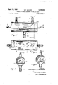
F-IG. 5 is a fragmentary side elevation view of the pressure conditioner unit employed in the water system of FIGS. 1-3;
FIG. 6 is a fragmentary top plan view of the pressure conditioner unit;
FIG. 7 is a cross-sectional view taken along line 77 of FIG. 5; and
FIG. 8 is a view similar to FIG. 7 but of an alternate embodiment of the bafiie plate in the pressure conditioner unit.
When like elements are used in each of the embodiments, common numerals are used in the drawings.
In (FIG. 1, a conventional water heater 7 is connected at its lower end by a pipe 11 to a cold water source (not illustrated). A pipe 42 extending from the top of the water heater 7 is connected to the inlet lower side of the chamber in a pressure conditioner unit 1.
The outlet side on top of the pressure conditioner unit 1-is connected by a pipe 12 to a mixing valve 9. The mixing valve 9 includes a housing 10 which has a conduit 11 in communication with the source of cold water, and the conduit 12 in communication with a source of hot water through the unit 1, and an outlet conduit 13 extends from the housing to a point of use, a shower head 15. The volume of water at the shower head is controlled by the solenoid actuated valve 28 in the outlet conduit 13.
Referring to =F-IG. 2 it can be seen that the housing :10 includes a passageway -16 connecting the cold water inlet and the outlet conduit 13. To control the water in this passageway, an ordinary solenoid actuated valve 17 has been inserted. A second passageway '19 in the housing connects the hot water inlet to the outlet conduit 13. In this passageway is a solenoid valve 20. A third passageway 22 in the housing 10 connects the mixing chamber 21 with the outlet conduit 13. The mixing chamber I211 includes an ordinary thermostatic controlled valve 35 between the hot water inlet and the cold water inlet;
Referring again to the embodiment in FIG. 1, it can be seen that the hot Water from conduit 12 passes through the pressure conditioner unit 1 which is connected to a conventional hot water heater 7 by pipe 42 and the cold water conduit 11 is connected to a source of cold water at the cold water connection on the Water heater.-
The pressure conditioner 1 is shown in FIGS. 58 in a modified form from that used in the system of FIG. 2 since unit 1' is designed to be connected to a plurality of mixing valves 9 such as the two mixing valves shown connected to the unit .1" in FIG. 3.
The unit 1' of FIGS. 5-7 includes an elongated cylindrical in cross-section tank 70 having a chamber 72 formed therein. The tank 70 is horizontally disposed and is provided with an inlet opening 74 connected to the pipe 42 extending to the outlet top end of the water heater 7. A pair of outlet openings 76 are provided in the top wall of the tank 70 and have pipes '12 extending therefrom for connection to a mixing valve 9. Also, outlet openings 78 .are formed in the opposite end wall of the tank 70.
Each of the outlet openings 76 and78 are disposed above a bafiie plate 80 extending the length of said tank 70. The fiat plate 80 is provided wtih a plurality of openings 82 through which water passes to reach the outlet openings 76 or 78. The plate '80 is secured by weldments 83 to the side wall of the tank 70.
A modified baffie plate 80' is illustrated in FIG. 8 and differs from that in FIGS. 5-7 by being convex upwardly rather than flat as is plate 80.
Certain of the components of the control assembly illustrated in FIG. 4 are schematically represented in FIGS. 1 and 3 by switches 29, 30, 31 and 33 which, respectively,
one of the other switches is in a closed position and its respective solenoid valve is energized. When the switch 33 is closed a maximum of water will flow due to the opening of the valve 28 in the outlet conduit 13. Any number of desired water temperatures may be obtained by opening and closing singularly or in combination the switches 29, 3t) and 31.
The switches in the control assembly 45 are operated on low voltage power of approximately 12 volts by use of step-down transformers 41 in the temperature switch circuit and the transformer 40 in the outlet conduit valve circuit. Lead-in lines 25 and 26 supply ordinary 110 line voltage. The low voltage across the solenoids will prevent their destruction in the event they remain energized when one or more of the switches are left closed for an extended period of time beyond normal usage. Additionally, the low voltage eliminates the possibility of the user being shocked while in contact with the water at the point of use.
The control assembly 45 additionally includes a signal light for each of the switches to indicate whether the switch is closed. Signal lights 46, 47, 48 and 49 will burn when the respective switches 31, 29, 30 and 33 are closed. The toggles 50, 51, 52 and 53, respectively, operate the switches.
In the embodiment illustrated in FIG. 3 of the drawings, the system of FIG. 1 is duplicated permitting two separate uses of the outlet water from a single source of inlet water, i.e., for a shower and a bath tub 44. To maintain a steady level of hot water flowing to each of the mixing valves 9 when both are in use, the hot water supply conduit 42 has a size of for example /1 inch to /2 inch for the outlet pipes 12 communicating with the mixing valve. v
Thus it is seen that the head of water pressure in the heater 7 is rendered ineffective in maintaining a high pressure at the point of useisuch as the tub 44 or shower 15 when the cold water source pressure is reduced. The pressure at the point of-use of the hot water is then substantially equal to the pressure of the cold water and therefore the temperature of the mixture remains constant.
From extended use of the system described, it has been found completely effective and comparable experience with mixing valves alone has proven totally unsatisfactory since the momentary drop in cold water pressure at the point of use is not accomplished by a corresponding reduction in the hot water pressure line and accordingly the temperature at the point of use is for a short, but intolerable period of time, too hot. Y
It can be appreciated that when the cold water source pressure is reduced such as by flushing a toilet or the like, the cold water pressure will be reducedto the mixing valve 9 as well as to the heater 7. If pressure conditioner 1' were not present, hot water from heater 7 would momentarily be supplied to mixing valve 9 at the same pressure which it previously was being supplied to due to the head of pressure within heater 7. This means that the hot water pressure in mixing valve 9 would be greater than the cold water pressure therein due to the reduction of cold water pressure. This would result in an increase in water temperature at the point of use for a short time. Pressure conditioner 1' momentarily prevents the head of water pressure in heater 7 from reaching mixing valve 9 due to the bafiie means therein resisting the surge of hot water. Pressure conditioner 1' momentarily resists the surge of hot water from heater 7 until the reduction in the hot water pressure line is effected. In eflect then, pressure conditioner 1 conditions or controls the pressure of the hot water between heater 7 and mixing valve 9 toprevent the water at the point of use from becoming too hot.
Some changes may be made in the construction and arrangement of my Selective Temperature Water Dispensing Means without departing from the real spirit and pur-*.
pose of my invention, and it is my intention to cover by my claims, any modified forms of structure or use of mechanical equivalents which may be reasonably included within their scope.
I claim:
1. In a liquid distribution system for supplying thermostatically controlled liquid to a point of use at a consistent pre-selected temperature, comprising,
a source of cold liquid,
a heater container having an inlet and an outlet, a heating means in said container and said cold liquid source being connected to said inlet of said container,
a pressure conditioner unit having a chamber formed therein and an inlet opening in communication with said chamber, said unit having an outlet openlng in communication with said chamber at a point remote from said inlet opening into said chamber,
a bafiie means in said chamber between said inlet of said chamber and said outlet of said chamber,
a pipe means connecting the inlet of said chamber to the outlet of said heater container,
a mixing valve connected by a pipe means to the outlet of said pressure conditioner unit,
a conduit connecting said cold liquid source to said mixing valve, said mixing valve having an outlet and means connecting said outlet to the point of use at a discharge staing means in said container and said cold liquid source being connected to said inlet of said container, a pressure conditioner unit having a chamber formed therein and an inlet openingin communication with said chamber,-said unit having an outlet opening in communication with said chamber at a point remote from said inlet opening into said chamber,
a bailie means in said chamber between said inlet of said chamber and said outlet of said chamber,
a pipe means connecting the inlet of said chamber to the outlet of said heater container,
said heater container having a capacity substantially greater than the capacity of said chamber in said pressure conditioner,
a mixing valve connected by a pipe means to the outlet of said pressure conditioner unit,
a 'conduit connecting said cold liquid source to said mixing valve,
said mixing valve having an outlet and means connecting said outlet to the point of use at a discharge station, and
means independent from said heater container and said ditioner unit is cylindrical in cross-section and elongated with its longitudinal axis being horizontally disposed.
5. In a liquid distribution system for supplying thermostatically controlled liquid to a point of use at a consistent pre-selected temperature, comprising,
a cold water source,
an upstanding heater container having an inlet adjacent its lower end and an outlet adjacent its upper end,
a heating means in said container and said cold water source being connected by a pipe means to said inlet of said heater container,
a pressure conditioner unit disposed above said heater container, said unit having a chamber formed therein and an inlet opening in communication with said chamber, said unit having an outlet opening in communication with said chamber,
a baffle means in said chamber between said inlet of said chamber and said outlet of said chamber,
a pipe means connecting the inlet of said chamber to the outlet of said heater container,
said heater container having a capacity substantially greater than the capacity of said chamber in said pressure conditioner,
a mixing valve connected by a pipe means to the outlet of said pressure conditioner unit,
a conduit connecting said cold liquid source to said mixing valve, said connection to said cold water source being adjacent the pipe connecting said cold water source to said heater container inlet,
said mixing valve having an outlet and means connecting said outlet to the point of use at a discharge station,
means indepedent of said heater container and said mixing valve for drawing cold water from said cold water source at times and thereby reducing the pressure of said cold water in said cold water source, said heater container inlet and said mixing valve, and thereby at the point of use.
6. The structure of claim 5 wherein said pressure conditioner unit has a fiat perforated baffle plate extending lengthwise in said chamber between the inlet and outlet of said unit.
7. The structure of claim 5 wherein said pressure conditioner unit has a convex upwardly in cross-section perforated baflle plate extending lengthwise in said chamber between the inlet and outlet of said unit.
References Cited by the Examiner UNITED STATES PATENTS 775,021 11/1904 Waterman 23612 1,522,120 1/ 1925 Halder. 1,985,929 l/1935 Jorgensen et a1. 23612 2,670,901 3/1954 Bierman 23612 2,895,676 7/ 1959 Kraft 23612 FOREIGN PATENTS 18,745 1895 Great Britain.
ALDEN D. STEWART, Primary Examiner WILLIAM F. ODEA, Examiner.
Claims (1)
1. IN A LIQUID DISTRIBUTION SYSTEM FOR SUPPLYING THERMOSTATICALLY CONTROLLED LIQUID TO A POINT OF USE AT A CONSISTENT PRE-SELECTED TEMPERATURE, COMPRISING, A SOURCE OF COLD LIQUID, A HEATER CONTAINER HAVING AN INLET AND AN OUTLET, A HEATING MEANS IN SAID CONTAINER AND SAID COLD LIQUID SOURCE BEING CONNECTED TO SAID INLET OF SAID CONTAINER, A PRESSURE CONDITIONER UNIT HAVING A CHAMBER FORMED THEREIN AN AN INLET OPENING IN COMMUNICATION WITH SAID CHAMBER SAID UNIT HAVING AN OUTLET OPENING IN COMMUNICATION WITH SAID CHAMBER AT A POINT REMOTE FROM SAID OUTLET OPENING INTO SAID CHAMBER, A BAFFLE MEANS IN SAID CHAMBER BETWEEN SAID INLET OF SAID CHAMBER AND SAID OUTLET OF SAID CHAMBER, A PIPE MEANS CONNECTING THE INLET OF SAID CHAMBER TO THE OUTLET OF SAID HEATER CONTAINER, A MIXING VALVE CONNECTED BY A PIPE MEANS TO THE OUTLET OF SAID PRESSURE CONDITIONER UNIT, A CONDUIT CONNECTING SAID COLD LIQUID SOURCE TO SAID MIXING VALVE, SAID MIXING VALVE HAVING AN OUTLET AND MEANS CONNECTING SAID OUTLET TO THE POINT OF USE AT A DISCHARGE STATION, AND MEANS INDEPENDENT FROM SAID HEATER CONTAINER AND SAID MIXING VALVE FOR DRAWING LIQUID FROM SAID COLD LIQUID SOURCE AT TIMES AND THEREBY VARYING THE PRESSURE WITHIN SAID HEATER CONTAINER.
Priority Applications (1)
| Application Number | Priority Date | Filing Date | Title |
|---|---|---|---|
| US399317A US3248054A (en) | 1964-09-25 | 1964-09-25 | Selective temperature water dispensing means |
Applications Claiming Priority (1)
| Application Number | Priority Date | Filing Date | Title |
|---|---|---|---|
| US399317A US3248054A (en) | 1964-09-25 | 1964-09-25 | Selective temperature water dispensing means |
Publications (1)
| Publication Number | Publication Date |
|---|---|
| US3248054A true US3248054A (en) | 1966-04-26 |
Family
ID=23579071
Family Applications (1)
| Application Number | Title | Priority Date | Filing Date |
|---|---|---|---|
| US399317A Expired - Lifetime US3248054A (en) | 1964-09-25 | 1964-09-25 | Selective temperature water dispensing means |
Country Status (1)
| Country | Link |
|---|---|
| US (1) | US3248054A (en) |
Cited By (1)
| Publication number | Priority date | Publication date | Assignee | Title |
|---|---|---|---|---|
| US4896658A (en) * | 1988-06-03 | 1990-01-30 | Matsushita Electric Industrial Co., Ltd. | Hot water supply system |
Citations (6)
| Publication number | Priority date | Publication date | Assignee | Title |
|---|---|---|---|---|
| GB189518745A (en) * | 1895-10-07 | 1896-08-15 | Reeves Patent Filters Company | Improvements in and connected with Pipes for Conducting and Distributing Liquids. |
| US775021A (en) * | 1902-06-24 | 1904-11-15 | Isaac G Waterman | Electrical-valve-controlling mechanism. |
| US1522120A (en) * | 1924-04-15 | 1925-01-06 | Fred W Halder | Hot and cold water mixer |
| US1985929A (en) * | 1932-01-19 | 1935-01-01 | Wilcolator Co | Thermostatically controlled fluid mixing device |
| US2670901A (en) * | 1951-08-01 | 1954-03-02 | Hartzell Industries | Fluid mixing valve |
| US2895676A (en) * | 1956-02-15 | 1959-07-21 | Dole Valve Co | Water tempering valve |
-
1964
- 1964-09-25 US US399317A patent/US3248054A/en not_active Expired - Lifetime
Patent Citations (6)
| Publication number | Priority date | Publication date | Assignee | Title |
|---|---|---|---|---|
| GB189518745A (en) * | 1895-10-07 | 1896-08-15 | Reeves Patent Filters Company | Improvements in and connected with Pipes for Conducting and Distributing Liquids. |
| US775021A (en) * | 1902-06-24 | 1904-11-15 | Isaac G Waterman | Electrical-valve-controlling mechanism. |
| US1522120A (en) * | 1924-04-15 | 1925-01-06 | Fred W Halder | Hot and cold water mixer |
| US1985929A (en) * | 1932-01-19 | 1935-01-01 | Wilcolator Co | Thermostatically controlled fluid mixing device |
| US2670901A (en) * | 1951-08-01 | 1954-03-02 | Hartzell Industries | Fluid mixing valve |
| US2895676A (en) * | 1956-02-15 | 1959-07-21 | Dole Valve Co | Water tempering valve |
Cited By (1)
| Publication number | Priority date | Publication date | Assignee | Title |
|---|---|---|---|---|
| US4896658A (en) * | 1988-06-03 | 1990-01-30 | Matsushita Electric Industrial Co., Ltd. | Hot water supply system |
Similar Documents
| Publication | Publication Date | Title |
|---|---|---|
| US2991481A (en) | Fluid distribution control system | |
| US4201518A (en) | Recirculating fluid pump control system | |
| US3349755A (en) | Recirculating flow water heater | |
| US3374957A (en) | Fluid flow control device | |
| US3175578A (en) | Water supply systems | |
| US2581855A (en) | Valve | |
| US2948277A (en) | Two temperature water heating system | |
| US3248054A (en) | Selective temperature water dispensing means | |
| US4323192A (en) | Control arrangements for heating circuits | |
| US2322872A (en) | Heating system | |
| US2807421A (en) | Combination hot water mixer and steam trap | |
| US2591400A (en) | Water heater system | |
| US2110251A (en) | Water heater | |
| US2830612A (en) | Anti-condensation device for flush tanks | |
| US2515885A (en) | Tempering unit | |
| US3734126A (en) | Liquid pressure conditioner | |
| US2700506A (en) | Thermostatically controlled fluid tempering device | |
| JPH0585815B2 (en) | ||
| US1577863A (en) | Water heater | |
| JPH05233077A (en) | Hot water supply system | |
| US2973151A (en) | Shower spray | |
| EP0048518A1 (en) | A district or block heating system | |
| GB742585A (en) | Improvements in and relating to thermally controlled valves | |
| KR200209680Y1 (en) | Control apparatus for heated room | |
| JPS6030943A (en) | Control device of hot-water storage type electric hot-water heater |