US3226071A - Seating - Google Patents
Seating Download PDFInfo
- Publication number
- US3226071A US3226071A US310228A US31022863A US3226071A US 3226071 A US3226071 A US 3226071A US 310228 A US310228 A US 310228A US 31022863 A US31022863 A US 31022863A US 3226071 A US3226071 A US 3226071A
- Authority
- US
- United States
- Prior art keywords
- pads
- frames
- seat
- seats
- seating
- Prior art date
- Legal status (The legal status is an assumption and is not a legal conclusion. Google has not performed a legal analysis and makes no representation as to the accuracy of the status listed.)
- Expired - Lifetime
Links
Images


Classifications
-
- A—HUMAN NECESSITIES
- A47—FURNITURE; DOMESTIC ARTICLES OR APPLIANCES; COFFEE MILLS; SPICE MILLS; SUCTION CLEANERS IN GENERAL
- A47C—CHAIRS; SOFAS; BEDS
- A47C1/00—Chairs adapted for special purposes
- A47C1/12—Theatre, auditorium or similar chairs
-
- A—HUMAN NECESSITIES
- A47—FURNITURE; DOMESTIC ARTICLES OR APPLIANCES; COFFEE MILLS; SPICE MILLS; SUCTION CLEANERS IN GENERAL
- A47C—CHAIRS; SOFAS; BEDS
- A47C11/00—Benches not otherwise provided for
- A47C11/005—Benches not otherwise provided for having multiple separate seats
-
- A—HUMAN NECESSITIES
- A47—FURNITURE; DOMESTIC ARTICLES OR APPLIANCES; COFFEE MILLS; SPICE MILLS; SUCTION CLEANERS IN GENERAL
- A47C—CHAIRS; SOFAS; BEDS
- A47C31/00—Details or accessories for chairs, beds, or the like, not provided for in other groups of this subclass, e.g. upholstery fasteners, mattress protectors, stretching devices for mattress nets
- A47C31/02—Upholstery attaching means
Definitions
- One of the fundamentals for increasing comfort is to introduce into the seat a certain degree of give or flex under the weight of the user so that it can, to some degree, reshape itself to conform to the users body. This eliminates the discomfort which arises from the use of rigid materials because they impose areas of concen trated pressure or resistance against the body.
- This invention is designed to accomplish this purpose. It provides a strong, durable frame capable of Withstanding not only heavy usage but even substantial abuse. At the same time, it provides the strength and durability at a reasonable cost because it standardizes and reduces to a bare minimum the number of individual components necessary to assemble the seating. This introduces substantial economies into the manufacture of the product. Further, a single design for seat and back frame structure is used both as the end frame and as the intermediate frames. Thus, a single frame structure serves all purposes, whether the seating is single or multiple.
- the invention also provides a construction in which the seat and back supporting pads can be quickly and easily removed, either for cleaning or for replacement. This materially reduces the cost of maintenance. Since the pads for each seat are separate and individual, damage to one seat may be repaired by replacement of the particular pad involved simply by its removal and the substitution of a new one.
- the pad construction is identical whether it is utilized for an end seat or for an in- 3,226,071 Patented Dec. 28, 1965 termediate seat where multiple seating is employed. In the preferred embodiment, separate seat and back pads are used. This further reduces the cost of replacement for wear and damage. This permits the economies of mass production to be applied to the pads and once again reduces both initial and maintenance costs.
- the invention permits flexible, cushioned pads to be utilized, thus giving a high degree of comfort.
- the pads have a resilient soft feel and conform to body contours, thus eliminating concentrated areas of resistance or pressure against the body which result in discomfort.
- the invention permits a simple, common, supporting standard to be used for a number of seats. This, again, simplifies structure and reduces initial cost.
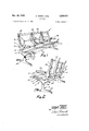
- FIG. 1 is an oblique front view of this invention
- FIG. 2 is an oblique rear view of this invention
- FIG. 3 is a side elevational view of the frame employed in this invention.
- FIG. 4 is a sectional elevational view taken along the plane IVIV of FIG. 3;
- FIG. 5 is a sectional elevational view taken along the plane VV of FIG. 3;
- FIG. 6 is a sectional elevational view taken along the plane VIVI of FIG. 3;
- FIG. 7 is a sectional elevational view taken along the plane VIIVII of FIG. 1, showing the seat pad installed;
- FIG. 8 is a sectional elevational view taken along the plane VIII-VIII of FIG. 3;
- FIG. 9 is a fragmentary, sectional elevational view taken along the plane IX-IX of FIG. 8;
- FIG. 10 is a fragmentary, sectional elevational view taken along the plane XX of FIG. 3 but showing the seat pad installed;
- FIG. 11 is a fragmentary, sectional elevational view taken along the plane XL-XI of FIG. 1;
- FIG. 12 is a plan view of the seat pad.
- each of the frames has a pair of cover plates which, in the case of the seat portion, forms the top surface of the frame and in the case of the back portion forms the front face of the frame.
- the cover plate for the back portion has an integral, forwardly projecting support for an armrest.
- the covers are removable and seat pads are suspended between the frames by placing their edge margins between the frames and the covers and clamping the covers down tightly on them to anchor the edges.
- the seat and back pads each are provided with grommets in their edge margins for reception of the studs. These provide an additional anchor for the seat and back pads, reinforcing the holding effect of the clamp formed between the covers and the frame.
- the seat 1 has a standard 2 on which is mounted a plurality of frames 3. All the frames 3 are identical irrespective of whether they are used at the ends or as the supports and dividers separating the individual seats.
- Each of the frames 3 has a somewhat L-shaped primary member 4.
- the primary member 4 has a seat portion 5 and a back portion 6 which are integral with each other. These portions are curved to provide comfortable seating.
- the back portion is somewhat concave.
- the seat portion, at its rear, is somewhat concave and forwardly is slightly convex. The particular shape of these portions is a matter of individual choice and may be freely varied within the limits of the invention.
- the back portion 6 has a channel 10 in its front face (FIGS. 3 and 4).
- the channel opens through the front face of the frame and its side edges are spaced somewhat inward from the sides of the frame, producing a pair of forwardly extending clamping edges 11 (FIG. 4).
- the channel 10 extends almost to the bottom of the back portion 6 and, in the area of the hereinafter described armrest, the channel is deepened for purposes which will be described more fully hereinafter.
- the clamping edges 11 are relieved at 12 to form a narrow, elongated cutout (FIG. 3).
- the seat portion 5 of the primary member 4 also has a channel 13 which extends to the front end of the frame.
- the channel 13 opens through the top of the primary member, and forms a pair of clamping edges 14, one along each side of the channel (FIG. 10).
- the channel 13 is deepened as indicated in FIG. 6. Rearwardly, the channel 13 terminates almost at the base of the back portion 6.
- the frame 3 may be fabricated from any suitable high strength material.
- it may be an aluminum casting which is given a highly attractive exterior finish by polishing. It will be recognized that it may be cast from other materials and finished in other ways. For example, it may be cast from steel and plated or coated with a suitable plastic to impart a corrosion resistant, decorative and attractive surface.
- the seat portion 5 has a cover plate 20.
- the forward portion of the cover plate is reversed back upon itself to form the hook 21 (FIGS. 8 and 9).
- the forward end of the primary member 4 has a projecting portion 22, the central portion of which seats in a cavity in the hook 21. This creates a pair of upturned lips 24 at the terminal end of the hook which engage under the projecting portion 22 and anchor the forward end of. the cover 20 against upward displacement.
- the clamping edges 14 of the primary member are relieved, forming narrow gaps 25.
- the cover 20 also has a recess 26 opening through its bottom face.
- the recess 26 forms a pair of clamping edges 27, one on each side, which match and cooperate with the clamping edges 14 of the primary frame.
- the recess 26 extends to a point approximately above the standard 2 where it is reversed and becomes a downwardly extending projection 80 (FIGS. 3 and 5). In this area the deepened channel 13 in the primary frame 4 provides space for the projection 80.
- the clamping edges 14 of the primary member 4 are relieved, forming a narrow gap 28 between the cover and the primary frame.
- the cover 20 extends rearwardly almost to the base of the back portion 6.
- the cover 20 is secured to the primary frame 4 by a stud 29 at its rearward end.
- the stud 29 is accessible from above and recessed in the cover 20.
- the stud 29 could be installed from below with its head recessed in the primary frame 4. This would permit its complete concealment.
- the cover 40 for the back portion, at its upper terminus, has a hook 41, identical in every way to the hook 21.
- the upper end of the primary frame 3 is shaped identically to the forward end of the primary frame and engages the hook 41 in the same manner.
- the primary frame is relieved at 12 adjacent the hook 41.
- the cover 40 has an internal recess 42 opening through the back face of the cover member which extends almost to the lower end of the cover except for an area adjacent the base of the armrest support 43 where the recess is eliminated and in its place the cover member 40 has a rearwardly extending boss 44 (FIGS. 3 and 4.)
- the lower end of the cover member 40 is relieved at 45.
- the cover 40 is secured to the primary frame by a cap screw 49 at its lower end.
- the projection forming the armrest support 43 is an integral part of the cover member 49 and extends forwardly from the cover member adjacent its lower end. It is located to be at a proper height to afford comfortable arm support for users of the seating. It mounts an armrest pad 46.
- the pad 46 has embedded in it a suitable plate or frame member 47 which is threadedly engaged by the screws 48. These attach the arm pad to the armrest support 43.
- the heads of the screws 48 are recessed in the bottom of the armrest support 43 to conceal them.
- the plate 47 is encased in a suitable material such as a fabric-reinforced vinyl material such as that sold under the name Naugahyde. It is also padded with a foam cushion between the outside covering and the plate for purposes of comfort.
- raised areas 31 are provided. In the particular embodiment illustrated, three of the raised areas 31 are provided in each of the seat portions 5 and the back portions 6. It will be recognized that'a greater or lesser number of these areas may be employed as required.
- a stud pin 32 is installed in each of the raised areas. The pins extend outwardly into the interior void created by the channels 10 and 42 and 13 and 26 respectively. Preferably they terminate just short of making contact with the cover plates 20 and 40.
- a socket 50 is provided in the bottom of the frame.
- the socket 50 is designed to seat about top flange 51 of the T-shaped horizontal bar 52 of the standard 2.
- the bar 52 seats closely in the socket, thus helping to align the frames, one with another, as they are placed on the bar. This also provides substantial stability and strength for each of the frames.
- the frame is attached to the standard 2 by bolts 53 which extend through the primary frame 3, suitable openings in the top flange 51 and into the top of the leg 54.
- the standard 2 has legs 54 at each end, each 'leg 54 being aligned beneath one of the frames 3. Intermediate legs may be added as necessary, particularly if the unit is lengthened. Access to the bolts 53 is had through the channel 13 which is deepened immediately above the downwardly projecting boss in which the socket 50 is formed.
- the intermediate frames are attached by threading holes in the top flange 51 of the bar 52.
- the bolts 53 are shorter and threadedly engage these holes in the top flange 51.
- the bar 52 also has a vertical flange 55 which seats firmly in a cross slot 56.
- a pair of bolts 57 extending front to rear in the leg 54 pass through the flange 55. These further secure the leg 54 to the bar 52 and when tightened tend to clamp the sides of the cross slot 56 against the faces of the flange 55.
- these bolts. are accessible from and recessed in the rear face of the leg to help conceal them.
- the length of the bar 521 will depend upon the number of seats which are going to be joined together on a common standard. As illustrated in FIG. 1, the bar 52 is long enough to accommodate four of the frames 3. These provide the frames. for three individual seats.
- Each of the legs 54 has a pair of feet 58 at its lower end, one extending forwardly and the other rearwardly. These are preferably integral with the vertical portion of the leg and may be fabricated as a single casting. It
- the body contacting portions of the seating are formed by the elements or pads 60 and 61.
- the pad 60 forms the back and the pad 61 the seat.
- Preferably the pads are identical. Therefore, the illustration of pad 60 in FIG. 12 may be considered typical.
- the pads 60 and 61 are next assembled to the frames.
- the pads 60 and 61 are mad-e with a wear and soil resistant, flexible surfacing material, as for example, a fabric-reinforced vinyl, such as that sold under the name Naugahyde.
- the pad is given thickness and body by a foam core. This also provides a resilient, cushioning effect, adding materially to the pads comfort.
- the pads are reinforced at each edge to give them strength and feel and yet the reinforcement is such that it does not form pressure areas of high resistance against the users body.
- each of the openings 63 may be surrounded by a suitable metallic device, such as a grommet 64.
- the pad may be reinforced by any suitable means such as by joining the front and back surfacing materials by suitable means such as sewing or heat sealing. Such reinforcements are indicated at 65. They may be arranged to provide ornamentation and, to this end, the pattern shown may be varied widely. It will be recognized that pads of different construction from that described may be used with the frame 3. Therefore, more detailed description of the pads is not considered necessary.
- T o secure the pads, they are first mounted by seating the grommets 64 over the stud pins 32. This anchors the pads to the frames. When the frame is an end one, only a single pad is secured as shown by FIG. 7. Where two of the pads are mounted to a single frame, both pads are mounted over the same stud pins 32, one on top of the other, as suggested in FIG. 11.
- the cover members 20 and 40 are then secured, first by hooking their outer ends over the ends of the frames and pivoting them into position. They are then drawn down tightly into clamping position by tightening the cap screw 29 in the case of the cover member 20 and the cap screw 49 in the case of the cover member 40. In this process, the hooks 21 and 41 act as hinges.
- Additional grommeted openings 63 are provided in the pads 60 and 61 to permit the cap screws 29 and 49 to pass through.
- the edge of the pad is forced inwardly into the deepened portion of the channel 16 of the primary frame 3. It will be seen, as indicated in FIG. 10, that the ridges 62 on the edges of the pads 60 and 61 are clamped within the hollow formed by the channels and recesses within the cover plates and the primary frame. This arrangement prevents the pads from slowly working their way out or withdrawing past the clamping edges due to the loads imposed by usage of the seats.
- a trim-strip 66 is used to dress up the frames 3 at the ends of the assembly.
- the trim-strip 66 has a wide exterior cover portion and neck portion terminating in somewhat enlarged inner bulb.
- the thickness of the neck portion is approximately that of the sides of the pads to keep the covers 20 and 40 level when clamped by substituting for the pad.
- the enlarged exterior head portion covers the joint between the covers and the frame and the inner bulb prevents the trim-strip from working its way from between the covers and the frame as clamping pressure is applied.
- the trim-strip 66 is preferably of an extruded plastic material such as vinyl.
- this arrangement for mounting the pads uses a minimum of parts. At the same time, it permits identical frames to be used both at the end of a group of seats and to support and separate each seat from its adjacent seats. It also provides a seat structure in which the pads can be quickly and easily changed either to change the color of the pads to accommodate the seating to any new motif of decoration or for cleaning or replacement necessitated by Wear or damage to the pads resulting from usage. This latter is most important because it permits the seats to be maintained at a reasonably low cost. Thus, it is always possible to maintain seating in such a manner that its appearance is attractive and in keeping with its surroundings. The failure of designs to permit this type of low cost, easy maintenance has been one of the outstanding faults of public seating constructed according to conventional designs.
- the tie bar 70 is applied.
- the tie bar extends the length of the seat and is secured to each of the individual frames where it seats against a rearwardly projecting boss 71 on each frame.
- the boss 71 is located approximately rearwardly of the armrest support 43.
- the tie bar 70 is secured by suitable fasteners such as cap screws 72. It will be recognized that while these fasteners are shown as cap screws, they could as well be designed to be flush or recessed.
- the cap screws pass through the boss 71 and threadedly engage suitable openings in the ridge 44 in the rear face of the cover member 40 (FIG. 3). This gives added support to the cover member 40 in the immediate area of the armrest 43, further reinforcing and stabilizing the armrest at this point.
- the ridge 44 provides a reinforced area around the screws 72 and at the base of the armrest support 43. This is desirable because this is an area of particularly high stress with a high incidence of twisting loads.
- the tie bar 70 provides a rigid spacing support for the frames, eliminating their tendency to attempt to twist about their sockets 50 due to the pull imposed by the back pads 60 when a person forcibly pushes back against these pads. They also resist the same sort of twisting action by the seat portions 5 due to loading of the pads 61 because they act to resist this twisting action at a point substantially back from the sockets 50. By this arrangement the positioning and stability of the frames is controlled at two spaced points rather than about a single fulcrum. This materially reduces the twisting load applied to the structure of the socket 50. This results in a frame structure of great strength which will stand the hard usage and abuse to which public seating is normally subjected.
- the hooks 21 and 41 not only serve as a positive anchor for the ends of the covers 20 and 40 but also serve to make the ends neat and smooth. This eliminates any sharp projections on these ends which could snag clothing or cause injury. They also give a neat and finished appearance to the frames.
- the standards 2 may be so constructed that the seating is portable or permanently anchored to the floor. The latter, of course, will be more common in public seating to prevent displacement which normally results from frequent usage. It will also be recognized that the standards may be made to any length suitable for the number of seats to be joined together as a unit. The design of the standard may be varied widely to adapt it to particular circumstances of use and design motif.
- the pads 60 and 61 are the only parts of the seating except the pads 46 of the armrests to contact the users body.
- the pads 60 and 61 are suspended, flexible supports. They are capable of giving or flexing under the weight of the user but at the same time, they have no appreciable stretching or elastic qualities. When pulled tightly across the gap between the frames 3 they are thus well adapted to support the weight of a person. At the same time they are capable of contouring themselves to the body of the user, eliminating areas of hardness or pressure against the users body. The elimination of such areas permits the seating to be used with a high degree of comfort for a long period. At the same time the pad provides firm support, thus giving the person a sense of security. They do not permit the person to sink deeply into the seat which facilitates sitting and rising.
- the seating is adapted to suflicient inclination of both the seat portion and the back that the person may sit in a comfortable position and have suflicient support that they have a sense of stability when using the seat.
- the positive anchoring of the pads prevents all possibility of the pads working loose which would allow them to sag and eventually produce a complete failure of support.
- a base in combination with an article of furniture comprising: a pair of upstanding supporting legs; the
- each of said legs being bifurcated to form a vertical slot having an upstanding arm on each side; a T-shaped bar having a horizontal flange and a vertical flange; said horizontal flange of said bar seated on the tops of said arms; said vertical flange seated in said slot in close fitting relationship to said arms; fastener means extending through said vertical flange and engaging both of said arms and clamping said arms tightly about said vertical flange when said fastener means is tightened; an article of furniture supported on said horizontal flange of said bar; and detachable mounting means extending from said article of furniture through said horizontal flange and securing said arms of said supporting legs.
Landscapes
- Health & Medical Sciences (AREA)
- Dentistry (AREA)
- General Health & Medical Sciences (AREA)
- Seats For Vehicles (AREA)
Abstract
946,391. Seats. HERMAN MILLER Inc. Sept. 26, 1962 [Oct. 2, 1961], No. 36576/62. Headings A4J and A4W. A seat comprises identical cast aluminium frames 3 joined by one or more flexible pads of fabric reinforced vinyl, forming seats and backs, whose edges are clamped between the frames 3 and cover members 20, 40, and fastened by pins 32 mounted between the frames and cover members 20, 40 and passing through openings 63 in the edges of the pad or pads. Identical back and seat pads 60, 61 can be used which are connected to the frames 3 with ridges 62 on the pads 60, 61 fitting into channels 10, 13 and recesses 42, 26 in the back and seat portions of the frames 3. The cover members 20, 40 are secured to the frames 3 by hooking their outer ends 21, 41 over the ends of the frames 3 and tightening cap screws 29, 49. Arm rests 43 are formed integral with the cover members 40 with pads 46 attached to them. Single seats can be formed or rows of seats with some frames 3 common to two seats. The cover members and pads are easily detachable for replacement or cleaning.
Description
Dec. 28, 1965 c. EAMES ETAL 3,226,071
SEATING Original Filed Oct. 2, 1961 3 Sheets-Sheet 1 ATTOAP/UEKS Dec. 28, 1965 c. EAMES ETAL SEATING 3 Sheets-Sheet 2 Original Filed Oct. 2, 1961 E msz w mm M W 3 f. ymp 6 Dec. 28, 1965 c EAMEs ETAL 3,226,071
SEATING Original Filed Oct. 2, 1961 3 Sheets-Sheet 3 INVENTORS 67/4715? [4/ 755 United States Patent 3,226,071 SEATING Charles Earnes, Venice, and Robert L. Staples, Manhattan Beach, Calif., assignors to Herman Miller, Inc., Zeelan'd, Mich., a corporation of Michigan Original application Oct. 2, 1961, Ser. No. 142,070, now Patent No. 3,114,575, dated Dec. 17, 1963. Divided and this application Sept. 20, 1963, Ser. No. 310,228
1 Claim. (Cl. 248-163) This invention relates to seating, and more particularly to a construction which is adapted to use as a single seat or expanded to provide multiple seating. While this invention may be applied in home furniture, it is particularly designed for public seating. This application is a division of our Patent No. 3,114,575 issued December 17, 1963.
In the field of public seating, such as in waiting rooms, airports, lobbies and similar places, the service demands placed upon seating facilities are severe. In the past, to make the seating durable, it was largely constructed of rigid, heavy material. Such seating-had the advantage of durability and low maintenance cost but it offered the public little or-no comfort. In recent years it has become increasingly necessary to provide more comfortable seating.
One of the fundamentals for increasing comfort is to introduce into the seat a certain degree of give or flex under the weight of the user so that it can, to some degree, reshape itself to conform to the users body. This eliminates the discomfort which arises from the use of rigid materials because they impose areas of concen trated pressure or resistance against the body.
The demand for more comfort and thus for cushioned or flexible seating has created a number of problems. The materials which provide this type of comfort do not have the durability of the more conventional rigid materials. Public seating is subjected to constant, hard wear. It is also often subjected to abuse and mistreatment. Partially because of the amount of usage and partially because of the carelessness of people, it rapidly becomes dirty, un-
attractive and gives the impression of sha'bbiness. This requires constant cleaning, maintenance, and replace ment. Because of the high cost of both labor and materials incident to proper maintenance, it is necessary that cleaning and replacement be made as quick and simple as possible. The cost of replacement materials must be kept reasonable. Without attention to these factors, the cost of maintaining safe, attractive, and effective seating cannot be kept within reasonable limits.
This invention is designed to accomplish this purpose. It provides a strong, durable frame capable of Withstanding not only heavy usage but even substantial abuse. At the same time, it provides the strength and durability at a reasonable cost because it standardizes and reduces to a bare minimum the number of individual components necessary to assemble the seating. This introduces substantial economies into the manufacture of the product. Further, a single design for seat and back frame structure is used both as the end frame and as the intermediate frames. Thus, a single frame structure serves all purposes, whether the seating is single or multiple.
The invention also provides a construction in which the seat and back supporting pads can be quickly and easily removed, either for cleaning or for replacement. This materially reduces the cost of maintenance. Since the pads for each seat are separate and individual, damage to one seat may be repaired by replacement of the particular pad involved simply by its removal and the substitution of a new one. The pad construction is identical whether it is utilized for an end seat or for an in- 3,226,071 Patented Dec. 28, 1965 termediate seat where multiple seating is employed. In the preferred embodiment, separate seat and back pads are used. This further reduces the cost of replacement for wear and damage. This permits the economies of mass production to be applied to the pads and once again reduces both initial and maintenance costs.
The invention permits flexible, cushioned pads to be utilized, thus giving a high degree of comfort. The pads have a resilient soft feel and conform to body contours, thus eliminating concentrated areas of resistance or pressure against the body which result in discomfort.
The invention permits a simple, common, supporting standard to be used for a number of seats. This, again, simplifies structure and reduces initial cost.
These and other objects and advantages of this invention Will be understood by those acquainted with the design and construction of seating upon reading the fol- .lowing specification and the accompanying drawings.
In the drawings:
FIG. 1 is an oblique front view of this invention;
FIG. 2 is an oblique rear view of this invention;
FIG. 3 is a side elevational view of the frame employed in this invention;
FIG. 4 is a sectional elevational view taken along the plane IVIV of FIG. 3;
FIG. 5 is a sectional elevational view taken along the plane VV of FIG. 3;
FIG. 6 is a sectional elevational view taken along the plane VIVI of FIG. 3;
FIG. 7 is a sectional elevational view taken along the plane VIIVII of FIG. 1, showing the seat pad installed;
FIG. 8 is a sectional elevational view taken along the plane VIII-VIII of FIG. 3;
FIG. 9 is a fragmentary, sectional elevational view taken along the plane IX-IX of FIG. 8;
FIG. 10 is a fragmentary, sectional elevational view taken along the plane XX of FIG. 3 but showing the seat pad installed;
FIG. 11 is a fragmentary, sectional elevational view taken along the plane XL-XI of FIG. 1; and
FIG. 12 is a plan view of the seat pad.
In executing the objects and purposes of this invention,
.there is provided a single frame structure having an insideration has to be given to the question of whether it is .to be used on the left end or the right end. These frames are secured to the common standard at spaced intervals. Each of the frames is identical. Each of the frames has a pair of cover plates which, in the case of the seat portion, forms the top surface of the frame and in the case of the back portion forms the front face of the frame. The cover plate for the back portion has an integral, forwardly projecting support for an armrest. The covers are removable and seat pads are suspended between the frames by placing their edge margins between the frames and the covers and clamping the covers down tightly on them to anchor the edges. In addition, the seat and back pads each are provided with grommets in their edge margins for reception of the studs. These provide an additional anchor for the seat and back pads, reinforcing the holding effect of the clamp formed between the covers and the frame.
Referring specifically to the drawings, the seat 1 has a standard 2 on which is mounted a plurality of frames 3. All the frames 3 are identical irrespective of whether they are used at the ends or as the supports and dividers separating the individual seats.
Each of the frames 3 has a somewhat L-shaped primary member 4. The primary member 4 has a seat portion 5 and a back portion 6 which are integral with each other. These portions are curved to provide comfortable seating. For this purpose, the back portion is somewhat concave. The seat portion, at its rear, is somewhat concave and forwardly is slightly convex. The particular shape of these portions is a matter of individual choice and may be freely varied within the limits of the invention.
The back portion 6 has a channel 10 in its front face (FIGS. 3 and 4). The channel opens through the front face of the frame and its side edges are spaced somewhat inward from the sides of the frame, producing a pair of forwardly extending clamping edges 11 (FIG. 4). The channel 10 extends almost to the bottom of the back portion 6 and, in the area of the hereinafter described armrest, the channel is deepened for purposes which will be described more fully hereinafter. For a short distance 'down from the upper end of the back portion 6, the clamping edges 11 are relieved at 12 to form a narrow, elongated cutout (FIG. 3).
The seat portion 5 of the primary member 4 also has a channel 13 which extends to the front end of the frame. The channel 13 opens through the top of the primary member, and forms a pair of clamping edges 14, one along each side of the channel (FIG. 10). In the area at the rear of the seat portion 5 immediately above the standard 2, the channel 13 is deepened as indicated in FIG. 6. Rearwardly, the channel 13 terminates almost at the base of the back portion 6.
The frame 3 may be fabricated from any suitable high strength material. For example, it may be an aluminum casting which is given a highly attractive exterior finish by polishing. It will be recognized that it may be cast from other materials and finished in other ways. For example, it may be cast from steel and plated or coated with a suitable plastic to impart a corrosion resistant, decorative and attractive surface.
The seat portion 5 has a cover plate 20. The forward portion of the cover plate is reversed back upon itself to form the hook 21 (FIGS. 8 and 9). To engage the hook 21, the forward end of the primary member 4 has a projecting portion 22, the central portion of which seats in a cavity in the hook 21. This creates a pair of upturned lips 24 at the terminal end of the hook which engage under the projecting portion 22 and anchor the forward end of. the cover 20 against upward displacement. For a short distance back from the forward end, the clamping edges 14 of the primary member are relieved, forming narrow gaps 25. The cover 20 also has a recess 26 opening through its bottom face. The recess 26 forms a pair of clamping edges 27, one on each side, which match and cooperate with the clamping edges 14 of the primary frame. The recess 26 extends to a point approximately above the standard 2 where it is reversed and becomes a downwardly extending projection 80 (FIGS. 3 and 5). In this area the deepened channel 13 in the primary frame 4 provides space for the projection 80.
In the area of the projecting ridge 80, the clamping edges 14 of the primary member 4 are relieved, forming a narrow gap 28 between the cover and the primary frame. The cover 20 extends rearwardly almost to the base of the back portion 6. In addition to the hook 21, the cover 20 is secured to the primary frame 4 by a stud 29 at its rearward end. The stud 29 is accessible from above and recessed in the cover 20. The stud 29 could be installed from below with its head recessed in the primary frame 4. This would permit its complete concealment.
The cover 40 for the back portion, at its upper terminus, has a hook 41, identical in every way to the hook 21. The upper end of the primary frame 3 is shaped identically to the forward end of the primary frame and engages the hook 41 in the same manner. As previously described, the primary frame is relieved at 12 adjacent the hook 41. The cover 40 has an internal recess 42 opening through the back face of the cover member which extends almost to the lower end of the cover except for an area adjacent the base of the armrest support 43 where the recess is eliminated and in its place the cover member 40 has a rearwardly extending boss 44 (FIGS. 3 and 4.) The lower end of the cover member 40 is relieved at 45. In addition to the hook 41, the cover 40 is secured to the primary frame by a cap screw 49 at its lower end.
The projection forming the armrest support 43 is an integral part of the cover member 49 and extends forwardly from the cover member adjacent its lower end. It is located to be at a proper height to afford comfortable arm support for users of the seating. It mounts an armrest pad 46. The pad 46 has embedded in it a suitable plate or frame member 47 which is threadedly engaged by the screws 48. These attach the arm pad to the armrest support 43. The heads of the screws 48 are recessed in the bottom of the armrest support 43 to conceal them. The plate 47 is encased in a suitable material such as a fabric-reinforced vinyl material such as that sold under the name Naugahyde. It is also padded with a foam cushion between the outside covering and the plate for purposes of comfort.
At suitable intervals in the channels 10 and 13, raised areas 31 are provided. In the particular embodiment illustrated, three of the raised areas 31 are provided in each of the seat portions 5 and the back portions 6. It will be recognized that'a greater or lesser number of these areas may be employed as required. In each of the raised areas a stud pin 32 is installed. The pins extend outwardly into the interior void created by the channels 10 and 42 and 13 and 26 respectively. Preferably they terminate just short of making contact with the cover plates 20 and 40.
At the rear end of the seat portion 5, a socket 50 is provided in the bottom of the frame. The socket 50 is designed to seat about top flange 51 of the T-shaped horizontal bar 52 of the standard 2. The bar 52 seats closely in the socket, thus helping to align the frames, one with another, as they are placed on the bar. This also provides substantial stability and strength for each of the frames. The frame is attached to the standard 2 by bolts 53 which extend through the primary frame 3, suitable openings in the top flange 51 and into the top of the leg 54. The standard 2 has legs 54 at each end, each 'leg 54 being aligned beneath one of the frames 3. Intermediate legs may be added as necessary, particularly if the unit is lengthened. Access to the bolts 53 is had through the channel 13 which is deepened immediately above the downwardly projecting boss in which the socket 50 is formed.
The intermediate frames, those being the ones which do not have a leg beneath them, are attached by threading holes in the top flange 51 of the bar 52. In this case the bolts 53 are shorter and threadedly engage these holes in the top flange 51.
The bar 52 also has a vertical flange 55 which seats firmly in a cross slot 56. A pair of bolts 57 extending front to rear in the leg 54 pass through the flange 55. These further secure the leg 54 to the bar 52 and when tightened tend to clamp the sides of the cross slot 56 against the faces of the flange 55. Preferably these bolts. are accessible from and recessed in the rear face of the leg to help conceal them. The length of the bar 521 will depend upon the number of seats which are going to be joined together on a common standard. As illustrated in FIG. 1, the bar 52 is long enough to accommodate four of the frames 3. These provide the frames. for three individual seats.
Each of the legs 54 has a pair of feet 58 at its lower end, one extending forwardly and the other rearwardly. These are preferably integral with the vertical portion of the leg and may be fabricated as a single casting. It
will be recognized that the design of the legs may be varied widely within the scope of this invention.
The body contacting portions of the seating are formed by the elements or pads 60 and 61. The pad 60 forms the back and the pad 61 the seat. Preferably the pads are identical. Therefore, the illustration of pad 60 in FIG. 12 may be considered typical. The pads 60 and 61 are next assembled to the frames. The pads 60 and 61 are mad-e with a wear and soil resistant, flexible surfacing material, as for example, a fabric-reinforced vinyl, such as that sold under the name Naugahyde. The pad is given thickness and body by a foam core. This also provides a resilient, cushioning effect, adding materially to the pads comfort. The pads are reinforced at each edge to give them strength and feel and yet the reinforcement is such that it does not form pressure areas of high resistance against the users body. The side edges of the pads are flat and are provided with ridges 62 which are received into the channel and recess 42 in the back portion and the channel 13 and recess 26 of the seat portion. The side edges of the panels are also provided with reinforced openings 63. For purposes of reinforcement, each of the openings 63 may be surrounded by a suitable metallic device, such as a grommet 64.
The pad may be reinforced by any suitable means such as by joining the front and back surfacing materials by suitable means such as sewing or heat sealing. Such reinforcements are indicated at 65. They may be arranged to provide ornamentation and, to this end, the pattern shown may be varied widely. It will be recognized that pads of different construction from that described may be used with the frame 3. Therefore, more detailed description of the pads is not considered necessary.
T o secure the pads, they are first mounted by seating the grommets 64 over the stud pins 32. This anchors the pads to the frames. When the frame is an end one, only a single pad is secured as shown by FIG. 7. Where two of the pads are mounted to a single frame, both pads are mounted over the same stud pins 32, one on top of the other, as suggested in FIG. 11. The cover members 20 and 40 are then secured, first by hooking their outer ends over the ends of the frames and pivoting them into position. They are then drawn down tightly into clamping position by tightening the cap screw 29 in the case of the cover member 20 and the cap screw 49 in the case of the cover member 40. In this process, the hooks 21 and 41 act as hinges. Additional grommeted openings 63 are provided in the pads 60 and 61 to permit the cap screws 29 and 49 to pass through. In this area of the ridge 44 on the back cover member 40, the edge of the pad is forced inwardly into the deepened portion of the channel 16 of the primary frame 3. It will be seen, as indicated in FIG. 10, that the ridges 62 on the edges of the pads 60 and 61 are clamped within the hollow formed by the channels and recesses within the cover plates and the primary frame. This arrangement prevents the pads from slowly working their way out or withdrawing past the clamping edges due to the loads imposed by usage of the seats.
To dress up the frames 3 at the ends of the assembly, a trim-strip 66 is used. The trim-strip 66 has a wide exterior cover portion and neck portion terminating in somewhat enlarged inner bulb. The thickness of the neck portion is approximately that of the sides of the pads to keep the covers 20 and 40 level when clamped by substituting for the pad. The enlarged exterior head portion covers the joint between the covers and the frame and the inner bulb prevents the trim-strip from working its way from between the covers and the frame as clamping pressure is applied. The trim-strip 66 is preferably of an extruded plastic material such as vinyl.
It will be understood that this arrangement for mounting the pads uses a minimum of parts. At the same time, it permits identical frames to be used both at the end of a group of seats and to support and separate each seat from its adjacent seats. It also provides a seat structure in which the pads can be quickly and easily changed either to change the color of the pads to accommodate the seating to any new motif of decoration or for cleaning or replacement necessitated by Wear or damage to the pads resulting from usage. This latter is most important because it permits the seats to be maintained at a reasonably low cost. Thus, it is always possible to maintain seating in such a manner that its appearance is attractive and in keeping with its surroundings. The failure of designs to permit this type of low cost, easy maintenance has been one of the outstanding faults of public seating constructed according to conventional designs.
After the pads 60 and 61 have been mounted, the tie bar 70 is applied. The tie bar extends the length of the seat and is secured to each of the individual frames where it seats against a rearwardly projecting boss 71 on each frame. The boss 71 is located approximately rearwardly of the armrest support 43. The tie bar 70 is secured by suitable fasteners such as cap screws 72. It will be recognized that while these fasteners are shown as cap screws, they could as well be designed to be flush or recessed. The cap screws pass through the boss 71 and threadedly engage suitable openings in the ridge 44 in the rear face of the cover member 40 (FIG. 3). This gives added support to the cover member 40 in the immediate area of the armrest 43, further reinforcing and stabilizing the armrest at this point. The ridge 44 provides a reinforced area around the screws 72 and at the base of the armrest support 43. This is desirable because this is an area of particularly high stress with a high incidence of twisting loads. The tie bar 70 provides a rigid spacing support for the frames, eliminating their tendency to attempt to twist about their sockets 50 due to the pull imposed by the back pads 60 when a person forcibly pushes back against these pads. They also resist the same sort of twisting action by the seat portions 5 due to loading of the pads 61 because they act to resist this twisting action at a point substantially back from the sockets 50. By this arrangement the positioning and stability of the frames is controlled at two spaced points rather than about a single fulcrum. This materially reduces the twisting load applied to the structure of the socket 50. This results in a frame structure of great strength which will stand the hard usage and abuse to which public seating is normally subjected.
The hooks 21 and 41 not only serve as a positive anchor for the ends of the covers 20 and 40 but also serve to make the ends neat and smooth. This eliminates any sharp projections on these ends which could snag clothing or cause injury. They also give a neat and finished appearance to the frames.
It will be recognized that the standards 2 may be so constructed that the seating is portable or permanently anchored to the floor. The latter, of course, will be more common in public seating to prevent displacement which normally results from frequent usage. It will also be recognized that the standards may be made to any length suitable for the number of seats to be joined together as a unit. The design of the standard may be varied widely to adapt it to particular circumstances of use and design motif.
The pads 60 and 61 are the only parts of the seating except the pads 46 of the armrests to contact the users body. The pads 60 and 61 are suspended, flexible supports. They are capable of giving or flexing under the weight of the user but at the same time, they have no appreciable stretching or elastic qualities. When pulled tightly across the gap between the frames 3 they are thus well adapted to support the weight of a person. At the same time they are capable of contouring themselves to the body of the user, eliminating areas of hardness or pressure against the users body. The elimination of such areas permits the seating to be used with a high degree of comfort for a long period. At the same time the pad provides firm support, thus giving the person a sense of security. They do not permit the person to sink deeply into the seat which facilitates sitting and rising. The seating is adapted to suflicient inclination of both the seat portion and the back that the person may sit in a comfortable position and have suflicient support that they have a sense of stability when using the seat. The positive anchoring of the pads prevents all possibility of the pads working loose which would allow them to sag and eventually produce a complete failure of support.
It will be recognized that numerous modifications of this invention may be made such as by reshaping the frames. The structure and design of the seating pad may be varied. The shape and design of the standard and of numerous other components of the unit may be modified. All of these changes are within the scope of the invention. Such modifications shall be considered as included in the hereinafter appended claim unless this claim by its language expressly states otherwise.
We claim:
A base in combination with an article of furniture comprising: a pair of upstanding supporting legs; the
upper end of each of said legs being bifurcated to form a vertical slot having an upstanding arm on each side; a T-shaped bar having a horizontal flange and a vertical flange; said horizontal flange of said bar seated on the tops of said arms; said vertical flange seated in said slot in close fitting relationship to said arms; fastener means extending through said vertical flange and engaging both of said arms and clamping said arms tightly about said vertical flange when said fastener means is tightened; an article of furniture supported on said horizontal flange of said bar; and detachable mounting means extending from said article of furniture through said horizontal flange and securing said arms of said supporting legs.
References Cited by the Examiner UNITED STATES PATENTS 2,796,307 6/ 1957 Knoll 248163 2,812,800 11/ 195 7 Eames 297-248 FOREIGN PATENTS 125,857 1901 Germany.
CLAUDE A. LE ROY, Primary Examiner.
Priority Applications (1)
| Application Number | Priority Date | Filing Date | Title |
|---|---|---|---|
| US310228A US3226071A (en) | 1961-10-02 | 1963-09-20 | Seating |
Applications Claiming Priority (3)
| Application Number | Priority Date | Filing Date | Title |
|---|---|---|---|
| CA712055T | |||
| US142070A US3114575A (en) | 1961-10-02 | 1961-10-02 | Seating |
| US310228A US3226071A (en) | 1961-10-02 | 1963-09-20 | Seating |
Publications (1)
| Publication Number | Publication Date |
|---|---|
| US3226071A true US3226071A (en) | 1965-12-28 |
Family
ID=41372789
Family Applications (2)
| Application Number | Title | Priority Date | Filing Date |
|---|---|---|---|
| US142070A Expired - Lifetime US3114575A (en) | 1961-10-02 | 1961-10-02 | Seating |
| US310228A Expired - Lifetime US3226071A (en) | 1961-10-02 | 1963-09-20 | Seating |
Family Applications Before (1)
| Application Number | Title | Priority Date | Filing Date |
|---|---|---|---|
| US142070A Expired - Lifetime US3114575A (en) | 1961-10-02 | 1961-10-02 | Seating |
Country Status (5)
| Country | Link |
|---|---|
| US (2) | US3114575A (en) |
| CA (1) | CA712055A (en) |
| CH (1) | CH420528A (en) |
| FR (1) | FR1339051A (en) |
| GB (1) | GB946391A (en) |
Cited By (13)
| Publication number | Priority date | Publication date | Assignee | Title |
|---|---|---|---|---|
| US4060277A (en) * | 1975-11-07 | 1977-11-29 | Leib Roger K | Modular furniture |
| DE2738925A1 (en) * | 1977-08-29 | 1979-03-08 | Thonet Geb Ag | Seating unit with metal frame - having slots to locate edges of panels and holes for arm rest fastening |
| FR2639809A1 (en) * | 1988-12-01 | 1990-06-08 | Haas Richard | Mattress with removable interchangeable element and its application to all kinds of bedding and seats, especially in cars, aeroplanes and cinemas |
| CN102770048A (en) * | 2010-01-29 | 2012-11-07 | 库施两合公司 | Seating furniture |
| US20120299347A1 (en) * | 2010-01-29 | 2012-11-29 | Kusch + Co., GmbH & Co., KG | Seating furniture |
| EP1711084B1 (en) * | 2004-01-27 | 2014-03-05 | G James Extrusion Co. Pty Ltd | Seats or benches with slats |
| US9060614B1 (en) * | 2013-08-13 | 2015-06-23 | Charles Augustus Gibilterra | Public seating system with interchangeable and replaceable modular web-design seats and backs |
| USD762074S1 (en) * | 2015-10-09 | 2016-07-26 | Charles Augustus Gibilterra | Modular public seating |
| USD826607S1 (en) * | 2016-11-15 | 2018-08-28 | Tecno S.P.A. | Support for a seating system |
| EP3701838A1 (en) | 2019-03-01 | 2020-09-02 | Lensvelt Contract B.V. | Waiting area seating furniture |
| NL2022666B1 (en) | 2019-03-01 | 2020-09-15 | Lensvelt Contract B V | Girder beam assembly |
| NL2022668B1 (en) | 2019-03-01 | 2020-09-15 | Lensvelt Contract B V | Seating furniture |
| US20200385126A1 (en) * | 2017-09-05 | 2020-12-10 | Textron Aviation Inc. | Modular seat |
Families Citing this family (23)
| Publication number | Priority date | Publication date | Assignee | Title |
|---|---|---|---|---|
| GB983047A (en) * | 1962-07-04 | 1965-02-10 | Vitafoam Ltd | Improvements in or relating to upholstered furniture |
| US3198578A (en) * | 1963-03-11 | 1965-08-03 | Ford Motor Co | Vehicle seat |
| US3230005A (en) * | 1964-01-27 | 1966-01-18 | Miller Herman Inc | Multi-seating assembly |
| US3258294A (en) * | 1965-06-09 | 1966-06-28 | Wadley Mann Inc | Knock-down chair |
| US3466087A (en) * | 1967-03-03 | 1969-09-09 | George F Motter | Modular seating combination |
| US3433549A (en) * | 1967-07-18 | 1969-03-18 | Vogel Peterson Co | Unit wall closet |
| US3565020A (en) * | 1968-07-15 | 1971-02-23 | Krueger Metal Products | Coat rack |
| US3531157A (en) * | 1968-08-23 | 1970-09-29 | Composite Structures Inc | Seat construction |
| US4299423A (en) * | 1979-12-13 | 1981-11-10 | Plantation Patterns, Inc. | Knockdown settee |
| DE3439135A1 (en) * | 1984-10-25 | 1986-04-30 | Wilkhahn Wilkening + Hahne GmbH + Co, 3252 Bad Münder | CHANGEABLE SEAT FACILITIES |
| USD426731S (en) * | 1998-02-13 | 2000-06-20 | Bieffe Di Bruno Ferrarese S.P.A. | Seat for beam-supported seating units |
| USD419314S (en) * | 1998-10-14 | 2000-01-25 | Chromcraft/Revington, Inc. | Multiple seating unit |
| US6095603A (en) * | 1998-10-22 | 2000-08-01 | Hock; Koh Tuang | Gang chair device |
| ES1043989Y (en) * | 1999-09-13 | 2000-08-01 | Figueras International Seating | PERFECTED BLOCK OF SEATS FOR AIRPORTS. |
| AUPQ297099A0 (en) * | 1999-09-21 | 1999-10-14 | Camatic Pty. Limited | Seating system |
| EP1541059A1 (en) * | 2003-12-09 | 2005-06-15 | Chung-Li Shieh | A structure of an improved chair |
| USD512573S1 (en) * | 2004-08-26 | 2005-12-13 | Martin Outdoor Media | Bus bench design |
| DE102010006174B3 (en) * | 2010-01-29 | 2011-06-16 | Kusch & Co. Sitzmöbelwerke GmbH & Co. KG | seating |
| US11071389B2 (en) | 2018-11-15 | 2021-07-27 | Series International, Llc | Beam seating system |
| US11026515B2 (en) | 2018-11-15 | 2021-06-08 | Series International, Llc | Beam seating system |
| JP1725968S (en) * | 2021-12-22 | 2022-09-29 | sofa | |
| US12408756B1 (en) | 2022-05-27 | 2025-09-09 | Series International, Llc | Stacking chair with removable back |
| USD1093929S1 (en) * | 2023-09-27 | 2025-09-23 | Arper S.P.A. | Bench |
Citations (3)
| Publication number | Priority date | Publication date | Assignee | Title |
|---|---|---|---|---|
| DE125857C (en) * | ||||
| US2796307A (en) * | 1954-08-20 | 1957-06-18 | Knoll Associates | Support for an article of furniture |
| US2812800A (en) * | 1956-05-03 | 1957-11-12 | Herman Miller Furniture Compan | Multiple seating assembly |
Family Cites Families (15)
| Publication number | Priority date | Publication date | Assignee | Title |
|---|---|---|---|---|
| US315617A (en) * | 1885-04-14 | Folding chair or settee | ||
| US365464A (en) * | 1887-06-28 | Seat for churches | ||
| US600852A (en) * | 1898-03-22 | Portiere or curtain pole | ||
| US584905A (en) * | 1897-06-22 | Bicycle-saddle | ||
| US596986A (en) * | 1898-01-11 | Office | ||
| US871679A (en) * | 1906-06-25 | 1907-11-19 | Eugene Feighery | Window-screen. |
| US1209452A (en) * | 1916-01-22 | 1916-12-19 | Robert E Kirsch | Multiple-seat unit. |
| GB151358A (en) * | 1919-06-21 | 1920-09-21 | Philip Cornish | Improvements in and relating to fixed seats for use in cinemas, theatres and the like |
| US1350027A (en) * | 1919-08-21 | 1920-08-17 | Monarch Metal Products Company | Metal window-screen |
| US1893481A (en) * | 1925-06-19 | 1933-01-10 | Walter A Adams | Table, bench, shelf, or similar structures |
| US1722226A (en) * | 1927-12-05 | 1929-07-23 | Forbes Mfg Co Inc | Joint cover for pews |
| US1829597A (en) * | 1928-03-03 | 1931-10-27 | Budd Edward G Mfg Co | Windbreak and securing means therefor |
| US2095625A (en) * | 1935-08-17 | 1937-10-12 | Edith I Allen | Multiple camp chair |
| US2281341A (en) * | 1938-11-23 | 1942-04-28 | Turner John | Chair or seat |
| US2737232A (en) * | 1952-11-04 | 1956-03-06 | Eli H Gruber | Back and seat construction for chairs and the like |
-
0
- CA CA712055A patent/CA712055A/en not_active Expired
-
1961
- 1961-10-02 US US142070A patent/US3114575A/en not_active Expired - Lifetime
-
1962
- 1962-09-26 GB GB36576/62A patent/GB946391A/en not_active Expired
- 1962-09-29 CH CH1148962A patent/CH420528A/en unknown
- 1962-10-01 FR FR910928A patent/FR1339051A/en not_active Expired
-
1963
- 1963-09-20 US US310228A patent/US3226071A/en not_active Expired - Lifetime
Patent Citations (3)
| Publication number | Priority date | Publication date | Assignee | Title |
|---|---|---|---|---|
| DE125857C (en) * | ||||
| US2796307A (en) * | 1954-08-20 | 1957-06-18 | Knoll Associates | Support for an article of furniture |
| US2812800A (en) * | 1956-05-03 | 1957-11-12 | Herman Miller Furniture Compan | Multiple seating assembly |
Cited By (18)
| Publication number | Priority date | Publication date | Assignee | Title |
|---|---|---|---|---|
| US4060277A (en) * | 1975-11-07 | 1977-11-29 | Leib Roger K | Modular furniture |
| DE2738925A1 (en) * | 1977-08-29 | 1979-03-08 | Thonet Geb Ag | Seating unit with metal frame - having slots to locate edges of panels and holes for arm rest fastening |
| FR2639809A1 (en) * | 1988-12-01 | 1990-06-08 | Haas Richard | Mattress with removable interchangeable element and its application to all kinds of bedding and seats, especially in cars, aeroplanes and cinemas |
| EP1711084B1 (en) * | 2004-01-27 | 2014-03-05 | G James Extrusion Co. Pty Ltd | Seats or benches with slats |
| US8931849B2 (en) * | 2010-01-29 | 2015-01-13 | Kusch + Co. Gmbh & Co. Kg | Seating furniture |
| US20120299348A1 (en) * | 2010-01-29 | 2012-11-29 | Kausch +Co. GmgH & Co. KG | Seating furniture |
| US20120299347A1 (en) * | 2010-01-29 | 2012-11-29 | Kusch + Co., GmbH & Co., KG | Seating furniture |
| US8764107B2 (en) * | 2010-01-29 | 2014-07-01 | Kusch + Co. Gmbh & Co. Kg | Seating furniture |
| CN102770048A (en) * | 2010-01-29 | 2012-11-07 | 库施两合公司 | Seating furniture |
| CN102770048B (en) * | 2010-01-29 | 2016-01-13 | 库施两合公司 | Seating application |
| US9060614B1 (en) * | 2013-08-13 | 2015-06-23 | Charles Augustus Gibilterra | Public seating system with interchangeable and replaceable modular web-design seats and backs |
| USD762074S1 (en) * | 2015-10-09 | 2016-07-26 | Charles Augustus Gibilterra | Modular public seating |
| USD826607S1 (en) * | 2016-11-15 | 2018-08-28 | Tecno S.P.A. | Support for a seating system |
| US20200385126A1 (en) * | 2017-09-05 | 2020-12-10 | Textron Aviation Inc. | Modular seat |
| US11713124B2 (en) * | 2017-09-05 | 2023-08-01 | Textron Innovations, Inc. | Modular seat |
| EP3701838A1 (en) | 2019-03-01 | 2020-09-02 | Lensvelt Contract B.V. | Waiting area seating furniture |
| NL2022666B1 (en) | 2019-03-01 | 2020-09-15 | Lensvelt Contract B V | Girder beam assembly |
| NL2022668B1 (en) | 2019-03-01 | 2020-09-15 | Lensvelt Contract B V | Seating furniture |
Also Published As
| Publication number | Publication date |
|---|---|
| FR1339051A (en) | 1963-10-04 |
| GB946391A (en) | 1964-01-15 |
| CA712055A (en) | 1965-06-22 |
| DE1429358A1 (en) | 1969-03-27 |
| US3114575A (en) | 1963-12-17 |
| CH420528A (en) | 1966-09-15 |
Similar Documents
| Publication | Publication Date | Title |
|---|---|---|
| US3114575A (en) | Seating | |
| US3124390A (en) | Seating pad attachment | |
| US3431022A (en) | Chair construction | |
| US3841704A (en) | Chair | |
| US3223450A (en) | Upholstered furniture | |
| US3669495A (en) | Upholstered seating furniture | |
| US2307331A (en) | Cushion | |
| US5064247A (en) | Wire rod office furniture stacking chair | |
| US3942836A (en) | Chair | |
| US3724897A (en) | Wire rod chair | |
| US4711495A (en) | Upholstered furniture | |
| US3807800A (en) | Upholstered item of furniture and cushion assembly | |
| US4131314A (en) | Seating furniture | |
| US3248147A (en) | Removable upholstery assembly | |
| US2965161A (en) | Chair leg or the like | |
| US3316018A (en) | Expansible chair | |
| US3174797A (en) | Replaceable upholstery for furniture | |
| US3578385A (en) | Demountable sofa or chair construction | |
| US4343509A (en) | Piece of seating furniture | |
| JPH06507569A (en) | decorative seating systems | |
| WO1980002791A1 (en) | Chair and seat-back unit therefor | |
| US3323835A (en) | Vehicle seat | |
| US3788701A (en) | Chair construction | |
| US2995182A (en) | Chair | |
| US2878861A (en) | Body supporting unit for furniture |