US3221484A - Crop-working implements - Google Patents
Crop-working implements Download PDFInfo
- Publication number
- US3221484A US3221484A US240305A US24030562A US3221484A US 3221484 A US3221484 A US 3221484A US 240305 A US240305 A US 240305A US 24030562 A US24030562 A US 24030562A US 3221484 A US3221484 A US 3221484A
- Authority
- US
- United States
- Prior art keywords
- tedder
- drum
- guide
- tined
- axis
- Prior art date
- Legal status (The legal status is an assumption and is not a legal conclusion. Google has not performed a legal analysis and makes no representation as to the accuracy of the status listed.)
- Expired - Lifetime
Links
Images


Classifications
-
- A—HUMAN NECESSITIES
- A01—AGRICULTURE; FORESTRY; ANIMAL HUSBANDRY; HUNTING; TRAPPING; FISHING
- A01D—HARVESTING; MOWING
- A01D78/00—Haymakers with tines moving with respect to the machine
- A01D78/02—Haymakers with tines moving with respect to the machine with tine-carrying bars or equivalent members which interconnect heads rotating about horizontal axes, e.g. of rotary-drum type
Definitions
- VAN DER LELY 3,221484 CROPWORKING IMPLEMENTS Filed Nov. 27, 1962 9 Sheets-Sheet 1 INVENTOR. OQNEL/ VAN 05/9 154 Dec. 7, 1965 C. VAN DER LELY 3,221,484
- An object of the invention is the provision of an effective and versatile implement which can deal readily with large accumulations of erop such as relatively high windrows.
- an implement of the kind set forth wherein a guide member is provided which projects forwardly of the implement during the use thereof and which extends across a part of the wiclth of the crop-working member
- This invention relates further to cropworking implements of the kind comprising a frame rnovable over the ground and a crop-working member journalled in the frame so as to be rotatable about a substantially horizontal axis.
- An object of the invention is the provision of an implement which can be used to form worked crop into a single relatively large swath.
- an implement of the kind set forth wherein a guide member is provided for displaced erop which guide 1nernber extends obliquely rearwardly, relative to the intended direction of travel, from one side of the implement, the guide member being constructed and arranged in such a way that, in the use of the implement, erop worked thereby can be deposited on a strip of land whose width is substantially less than the width of the erop-techniking member and which is located towards the side of the implement remote from the side to which the guide member is connected.
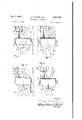
- FIGURE 1 is a plan view of a tedder in accordance with the invention coupled to the rear of a tractor;
- FIGURE 2 is a side elevation, to an enlarged scale, of the tedder of FIGURE 1;
- FIGURE 3 is a view as seen in the direction indicated by the arrow III of FIGURE 2;
- FIGURE 4 is a view similar to FIGURE 3 but showing further parts of the implement in greater detail;
- FIGURE 5 is a view, to an enlarged scale, as seen in the direction indicated by the arrows VV of FIG- URE 1;
- FIGURE 6 is a view, to an enlarged scale, as seen in the direction indicated by the arrow VI of FIG- URE 1;
- FIGURE 7 is a sectional elevation of part of the tedder of FIGURE 1 showing the provision of a guide member
- FIGURE 8 illustrates the guide member of FIGURE 7 as seen in the direction indicated by the arrow VIII of that FIGURE;
- FIGURE 9 illustrates one method of operating the tedder of FIGURE 1;
- FIGURE 10 illustrates a second method of operating the tedder
- FIGURE 11 illustrates a third method of operating the tedder
- FIGURE 12 illustrates a fourth method of operating the tedder
- FIGURE 13 illustrates a fifth method of operating the tedder to produce the same result as the fourth method just mentioned
- FGURE 14 is a plan view of an implement in accorclance with the invention.
- FIGURE 15 is a side elevation of part of the implement of FIGURE 14 as seen in the direction indicated by the arrow XIV of FIGUR.E 14;
- FGURE 16 illustrates a method of using the implement of FIGURES 14 and 15;
- FIGURE 17 is a plan view of an alternative embodiment of an implement in accordance with the invention.
- the tedder has two main frame beams 2, 202 which are arranged one above the other and which both extend parallel to the axis of rotation of a tined body or drum 1 which is rotatably journalled in the frame of the tedder.
- T'ne upper frame beam 2 is provided at its opposite ends with two frame beams 3 which are contained in a horizontal plane and which project rearwardly of the frame beam 2 at an angle of other than thereto.
- the ends of the bearns 3 and 1 remote from the bearns 2, 2192 are secured to vertical bearings 5 in which vertical shafts 6 are rotatably journalled.
- the shafts 6 are connected by inclined arms 7 to horizontal axles upon which ground wheels 3 are rotatably mounted.
- the ground wheels 8 are castor wheels and means (not shown) is preferably provided to enable the levels of their axles to be adjusted relative to that of the frame It will be apparent that such adjustment will change the level of the frame relative to the surface of the ground.
- Further means which is not illustrated in detail in the drawings is also provided whereby the plane of rotation of at least one of the ground wheels 8 can be retained in chosen angular settings about the longitudinal axis of the corresponding vertical shaft (6. This allows the disposition of the tedder to be fixed relative to the direction of travel thereof.
- a vertical pivot pin 10 is connected to the lower frame beam 2112 by means of a support 9 and one end of a draw-bar 11 is turnable about the pin 111
- An approximately semi-cylindrical strip 11 whose center of curvature coincides with the longitudinal axis of the pivot pin 10 has its opposite ends secured to the lower frame beam 202.
- a bracket 12A is carried by the upper side of the draw-bar 11 and supports a horizontal .locking pin 12 whose tip aan enter any one of a number of holes 13 formed in the strip 14. It will be apparent that the hole 13 which is selected to co-operate with the locking pin 12 will determine the angular setting of the draw-bar 11 about the pivot pin 10.
- Two vertical plates 15 extending perpendicular to the frame beams 2, 202 are mounted adjacent the opposite ends of those frame beams, the upper and lowerrnost edges 16 of the plates 15 being bent over so as to project horizontally.
- the plates 15 carry aligned horizontal bearings (not shown) which define an axs of rotation afforded by a central shaft (not shown) of the tined body or drum 1, the said shaft being parallel to the two main frame beams 2, 202.
- the drum 1 includes a number of approxirnately square plates 17 arranged at rightangles to the axis of rotation, these plates carrying four tine supports 18 which extend parallel to the axis of rotation and to each of which a plurality of tines 19 is secured.
- a gear casing 20 is secured to the side of one of the plate remote from the tned body or drum 1 and contains a bevel gear rigidly secured to the corresponding end of the central shaft of the tned body or drum.
- the gear casing also accommodates a second bevel gear whose teeth are in rnesh with those of the gear just rnentioned and which is rigidly secured to one end of a shaft (not visible) which extends forwardly of the tedder at right-angles to the axis of rotation of the body or drum 1.
- the sad shaft is disposed within a protectve cylindrical sleeve or casing 21 whose front end opens into a further casing 22.
- the leading end of the sad shaft carries a sprocket disposed within the casing 22 which sprocket is connected by an endless chain to a further sprocket carried by a shaft 23 whose leading splined end projects forwardly of the casing 22.
- the tedder has a bafle or hood which is generally indicated by the refereuce nurneral 24 and which comprises two opposite side or end plates 25 extending perpendicular to the axis of rotation of the body or drum 1 and a curved plate 26 which is bent so as to surround part of the body or drum 1.
- the lowermost leading edge of the plate 26 is located at the level of the lower frame beam 202.
- the lowermost edges 27 of the side or end plates 25 are bent over horizontally and rest upon the uppermost edges 16 of the two plates 15. Bolts are empl0yed to fasten the edges 27 and 16 to one another.
- the guide member 28 which is symmetrically identical with the lguide rnember 31, includes a support 32 to which six spring steel guide rods 33 are secured.
- the guide rods 33 are located one above the other, the inclinations of the rods to the horizontal progressively increasing from the uppermost rod to the lowermost rod.
- the rods are inclined at different angles to a plane extending perpendicular to the axis of rotation of the body or drum 1.
- the inclinations of the rods to sad plane progressively increase from the uppermost rod to the lowermost rod.
- the support 32 is connected with a pivot pin 34 which is located in a vettical plane and which is journalled in a sector plate 35 carred by a tube 36 whose opposite ends have horizontally aligned stub shafts or gudgeons 37.
- the guide member 28 with its support 32 can be turned about the longitudinal axis of the pivot pin 34 and can be retained in any one of a nurnber of diterent angular settings about the sad axis by entering a locking pin 44 through a hole in an arm 42 rigid with the pivot pin 34 and through a chosen one of a nurnber of holes 43 formed in the sector plate 35 at equal distances from the pivot pin 34.
- the guide member 28 can also be turned about the horizontal axis afforded by the stub shafts or gudgeons 37, this axis extending parallel to the axis of rotation of the body or drum 1.
- the stub shafts 01' gudgeons 37 are journalled in two lugs 38 secured to the plate 26.
- One of the stub shafts or gudgeons 37 carries a ring 39 formed with a nurnber of holes 40.
- a single registering hole is formed in the adjoining lug 38 and a locking pin 41 can be entered through a chosen hole and the hole in the lug 38 to retain the tube '36, and thus the guide member 23, in a corresponding angular setting about the axis afforded by the stub shafts or gudgeons 37.
- two lugs 45 are secured to the plate 26 adjacent the center thereof.
- Stub shafts or gudgeons 47 arranged at the opposite ends of a tube 46 are journalled in these lugs in such a way that the tube 46 is turnable about an axis extending parallel to the axis of rotation of the body or drum 1.
- a chosen angular setting of the tube 46 about sad axis can be maintained with the aid of a locking pin 48 in substantially the same manner as has just been described in connection with the tube 36.
- a double sector plate 49 projects rearwardly of the tube 46 and is formed with two rows of holes 50.
- Two pivot pins 51 contained in vertical planes are journalled in the double sector plate 49 and carry supports, generally similar to the support 32, to which the guide members 29 and 30 are respectively connected.
- Bach of the guide members 29 and 30 can be retained in a chosen angular setting about the longtudinal axis of the corresponding pivot pin 51 by enterng a locking pin 53 through a hole in an arm 52 rigidly secured to the sad pivot pin and through a selected one of the holes 50.
- the guide members 29 and 30 are similar to the guide members 28 and 31 in consisting principally of a number of spring steel guide rods.
- theguide rods of the guide members 29 and 30 are disposed in a similar manner to the guide rods 33 (FIGURE 2) of the guide member 28.
- the guide rods are located, in the position in which they extend substantially perpendicular to the axis of rotation of the body or drum 1, vertically above one another throughout the greater parts of their lengths, only the free ends 54 thereof being bent over towards the. guide mernber 28 in the case of the guide member 29 and towards the guide rnember 31 in the case of the lguide member 30.
- the guide members 29 and 30 can be retained in positions in which they are in very close proximity t0, or actual contact with, one another.
- the concave side of the plate 26 facing the body or drum 1 is provided with two plates 55 and 56 (FIGURE 5) which project substantially at right-angles to the plate 26.
- the lowermost edges 57 and 58, respectively, of the plates 55 and 56 are bent over from the center of the plate 26 towards the opposite ends thereof.
- the roots of the two edges 57 and 58 are, in addition, joined to one another by a strengthening plate 59 which closes all but the rearmost end of the space between the plates 55 and 56.
- the rearmost ends of the two plates 55 and 56 are spaced apart from one another by a distance which is such that the supports (not shown) of the two guide mem bers 29 and 30 are located between thern when considered in a direction perpendicular to the axis of rotation of the tned body or drum 1. Moreover, in side elevation, tne rearmost ends of the edges 57 and 58 are located at about the same height as the lowermost ends of the supports which have just been rnentioned. As can be seen in FIGURES 2, 5 and 7, the plates 55 and 56 progressively decrease in height towards the front of the tedder and also converge towards one another so that they eventually merge into the plate 26 at a single point.
- the leading end of the draw-bar 11 can be employed to connect the tedder to the tow-bar of a tractor such as the tractor 60 which is illustrated in FIGURE 1.
- the shaft 23 is placed in driven connection with the power takeo shaft of the tractor 60 by means of a telescopic transmission shaft 61 having universal joints at its opposite ends.
- the tedder can thus be moved over the ground in the direction indicated by the arrow Q (FIGURES 1 and 2) while the tned body or drum 1 is rotated in the direction indicated by the arrow P (FIGURE 2).
- the casing 22 may be provided with an additional shaft 23A (FIGURE 9) which is so arranged that, when the transmission shaft 61 is connected thereto, the tned body or drum 1 will be rotated in a direction opposite to the direction P with a constant direction of rotation of the power take-off shaft of the tractor 60.
- a central region 62 (FIGURE 6) of the lowermost frame beam 202 is oflset upwardly relative to opposite end portiens 63 of the sarne frame beam.
- the lowerrnost leading edge of the plate 26 of the baflle 24 is shaped te match the configuratien of the lowermest frame beam 202. It is preferred that the eentral regien 62 should have a width equal te about one-third of the width of the tined body er drum 1.
- FIGURES 7 and 8 show the previsien of a guide member whieh is afforded by a plate 64 arranged at the front of the tedder.
- the upper side of the plate 64 is provided with lugs 65 in whieh a herizontal shaft 66 extending parallel te the axis of: rotation of the body er drum 1 is journalled.
- the shaft 66 is also jeurnalled in two sector plates 67 carried by the eentral portien 62 of the 10W- ermost frame bearn 202.
- One of the two lugs 65 is eX- tended te form a handle 68 in whieh a single hole is formeel that can be brought into register with any one of a number of holes 69 formed in an adjaeent one of the two sector plates 67.
- the plate 64 Upon entering a horizontal leek ing pin 70 through the registerng holes, the plate 64 will be retained in an angular setting about the shaft 66 corresponding te the engageular hole 69 whieh has been ehosen.
- the leading edge 71 of the plate 64 is eurved upwardly while a series of ribs 72 is provided en the lowermest side of the plate.
- the ribs 72 are arranged in two series whieh are oppesitely inelined at angles of other than 90 to the axis of rotation of the tined body er drum 1, there being a spaee between the two series in which the lower side of the plate 64 ear1ies ne projecting members.
- the plate 64 limits the height of the cut erop which is sup plied te the tined body er drum 1.
- the plate 64 will be moved te diflerent angular settings about the shaft 66 in aeeordance with the original height of the cut erop whieh is te be werked so that the whole of a swath may be eflectively guided into contact With the body er drum 1.
- the ribs 72 act te distribute erop passing beneath the plate 64 towards the oppesite sides er ends of the body er drum 1 so that the said erop is more er less uniformly distributed throughout the width of the body er drum.
- the plate 64 is preferably positioned in such a way that a line of intersection between ts own plane and a vertieal plane extending perpendicular te the axis of rotation of the body er drum 1 makes an angle of net more than 45 with the herizontal.
- the width of the plate 64 in a direetion parallel te the axis of retatien of the body or drum 1 is preferably in exeess of ene-sixth of the width of the body er drum and, in the embodrnent illustrated, the width of the said plate is equal te approximately one-third of the width of the body er drum 1.
- the rearmost edge 73 of the plate 64 prejeets rearwardly of the lowermest edge of the plate 26 and is located at a level slightly below the level of the axis of rotation of the body er drum 1.
- the plate 64 may be rigidly seeured to the frame of the tedder instead of pivotable relative thereto as illustrated.
- the plate 64 may be mounted so as te be slidable te different positions relative te the frame.
- the plate 64 may be turned about the shaft 66 until it is substantially vertieally disposed, the loeking pin 70 being ernployed te maintain this pesition.
- edge 73 thereef will then itself be substantially vertieally disposed and will oeeupy a position such that it censtitutes an extension of the plate 26 in the region thereof whieh is foreshortened te match the central region 62 of the lowermest frame bearn 202.
- the implement whieh has been deseribed in detail takes the form of a tedder, it will be apparent that a number of the features of the invention eould equally well be applied to other implements for werking crops.
- FIGURE 2 It will be apparent frern FIGURE 2 that, during operatien of the tedder, erop engaged by the tines 19 is moved upwardly in front of the body or drum 1 and then rearwardly over the top thereof beneath the baflle 24 from the rearmost end of which it is ejeeted se as te fall te the ground to the rear of the tedder.
- the tedder may be employed in several different ways. For example, in FIGURE 1, the tedder is shown werking two relatively spaced swaths of mown erop.
- the guide members 28 and 31 are arranged so that the displaeed erop is deflected towards the center of the tedder whereas the guide members 29 and 30 are arranged in contact with one another and substantially perpendieular te the axis of rotatien of the body er drum 1 so that they have 110 appreeiable effect upon the displaeed erop.
- the guide members 29 and 30 ean in fact, be turned upwardly about the longitudinal axis of the tube 46 to a postion in whieh they lie wholly er mainly above the bafiie 24 in whieh pesitien they are not eontaeted te any appreeiable extent by the displaeed erop.
- the two relatively spaeed swaths A and B are thus conveyd into a single windrow C whose width is very apprexirnately equal te the width of ene of the two swaths A and B.
- the erop may advantageously be depesited on the ground in this way during wet weather sinee it tends te absorb less water in the form of a single windrow than in the form of two separate relatively flat swaths.
- the windrow C ean be spread over the land in the manuer illusrated in Figure 9.
- the windrow C meets a central region of the body er drum 1 and the guide members 28 and 31 are dispesed approximately perpendicular te the axis of rotatien of the body er drum.
- the guide members 28 and 31 ean be turned upwardly about the longitudinal axes of the tubes 36 until they are dispesed wholly er partly abeve the baflle 24.
- the guide members 29 and 30, on the ether hand, are arranged in divergent relationship at a level such that some, but not all, the erop is deflected thereby.
- a substantally uniform distribution of the displaeed erop threughout the width of the tined body er drum 1 is predueed.
- the guide member afforded by the plate 64 may be employed in the manner illustrated in Figure 9. The windrow C is then fiattened te a eertain extent by the plate 64 whle the ribs 72 initiate the displacement of the cut erop towards the epposite sides er ends of the body er drum 1.
- the tedder may be employed te aehieve this by using it in the manner illustrated in FIGURE 10.
- the guide members 28 te 31 are all arranged at angles of ether than te the axis of rotation of the body er drum 1 and are also disposed at a level such that substantially all the displaeed erop is deflected thereby. As ean be seen in FIGURE 10, this results in the produetien of two relatively narrow swaths D and E.
- the dried erop When the dried erop is te be eolleeted, it is preferably first arranged in the form of a single large windrow F in the manner illustrated in FIGURE 11.
- FIGURE 11 aetually shows the manner in whieh the tedder is used te re-distribute the two swaths D and E in the form of the single windrow F but it will be appreeiated that the tedder eould equally be empleyed te preduee the windrow F from erop spread Widely over the field te dry.
- the guide members 28 and 31 are substantially inelined towards one another While the guide members 29 and 30 are arranged in contact with one another or are turned to a position above the bafile 24 so that they do not deflect the crop to any appreciable extent.
- the tedder may be arranged so that the axis of rotation of the tined body or drum 1 is inclined at an angle of other than 90 to the direction of travel of the redder. This may be done by appropriate adjustment of the setting of the plane of rotation of one, or both, of the ground wheels 8.
- FIGURES 12 and 13 illustrate methods of using the tedder in this manner to displace two relatively small windrows F and G laterally to form a single relatively large windrow H.
- FIGURE 12 illustrates a method in which the tractor 60 makes successive traverses of the field in the same direction
- FIGURE 13 illustrates a method in which the tractor 60 makes successive traverses in relatively opposite directions. It will be apparent that the result is substantially the same in both cases.
- the method of FIGURE 13 has the advantage that re-positioning of the tedder relative to the tractor 60 is unnecessary between successive traverses.
- the tedder may also be used in the manner illustrated generally in FIGURES 12 and 13 to form a single windrow to one side of the path of travel of the tractor 60.
- the implement illustrated in FIGURES 14 and 15 has a man frame beam 81 to the opposite ends of which two beams 82 and 83 are secured so as to project perpendicularly.
- a bracket 84 is secured to the frame beam 82 adjacent the free end thereof and a further bracket 84 is secured to the frame beam 81 adjacent its junction with the frame beam 83.
- Vertical shafts 86 are journalled in the brackets 84 and the lowermost ends of these shafts are bent to form horizontal axles upon which ground wheels 85 are rotably mounted. The longitudnal axes of the axles of the wheels 85 do not intersect the longitudinal axes of the shafts 86 so that the said ground wheels -are castor wheels.
- Means includng screwthreaded cranked spindles 85A are provided whereby the levels of the axles of the ground wheels 85 can be changed relative to the frame of the implement and thus the level of the frame of the implement relative to the ground.
- locking means generally indicated by the reference numeral 87 are provided by which the planes of rotation of the two ground wheels 85 can be retained in selected angular settings about the vertical axes alforded by the shafts 86.
- a crop-working member afforded by a tined body or drum 88 is journalled in the frame so as to be rotatable about a substantially horizontal axis extending substantially parallel to the frame beam 81.
- the effective diameter of the body or drum 88 is about 100 centimeters while its elfective width in a direction parallel to its own axis of rotation is about 300 centimeters.
- the body 01 drum 88 is, in tact, rotatably supported in bearings carried by the frame beams 82 and 83, the arrangement of these bearings not being illustrated in detail in the drawings.
- One end of the body or drum 88 has a pulley 90 secured to it aronnd which an endless belt, rope or the like is passed.
- the belt, rope or the like extends within a casing 89 secured to the frame and also passes around a further pulley secured to one end of a shaft extending axially of a cylindrical casing 91 connected to the main frame bearn 81.
- the end of said shaft remote from the casing 89 is disposed within a gear casing 92 and carries a pinion whose teeth are in mesh with those of a further pinion mounted on a shaft (not shown) whose splined or otherwise keyed end projects forwardly of the implement from the gear casing 92.
- a drawbar 93 projects forwardly of the implement and is connected to the frame beam 81 in such a way that it can be retained in selected angular settings relative to that frame beam.
- the leading end of the draw-bar 93 is, of course, provided with means whereby it can be connected to a tractor or other propelling vehicle.
- the implement includes a bood or baffle 94 which surrounds a portion of the body or drum 88 and which extends from the level of the frame beam 81 upwardly and rearwardly over the said body or drum 88.
- a bar 95 of L-shaped crosssection is secured to the rearmost upper edge of the baffle 94 and the uppermost ends of two tubes 96 are rigidly secured to the opposite ends of this bar. T he lower ends of the tubes 96 are rigidly connected to the frame of the implement.
- a guide member for crop displacement by the implement is mounted so as to be adjustable in position relative to the plates 97 and 98.
- the guide member 99 is comprised principally by eight spring steel guide rods 100, 101, 102, 103, 104, 105, 106 and 107. The ends of such rods are clamped to a supporting plate 109 by means of a clamping plate 116A and a plurality of bolts 116.
- a second supporting plate 108 is parallel to, but spaced from, the supporting plate 108, a sleeve 110 accommodating a shaft 111 extending perpendicularly between these plates.
- the shaft 111 aifords an axis about which the guide member 99 is turnable relative to the frame of the implement and its opposite ends are journalled in holes formed in the plates 97 and 98, respectively.
- the shaft 111 is, in fact, located in a vertical plane extending parallel to the axis of rotation of the tined body or drum 88 and is inclined to the horizontal at an angle of about 20, the uppermost end of the shaft being disposed towards the center of the implement.
- the supporting plates 108 and 109 are formed with aligned holes through which a spring-loaded locking pin 112 is entered.
- a portion of the plate 97 which projects rearwardly of the bafiie 94 is formed with a number of holes 113 arranged equidstant from the shaft 111.
- the tip of the locking pin 112 can enter a chosen one of the holes 113 to retain the supporting plates 108 and 109 together with the guide member 99 in a corresponding angular setting about the axis afforded by the shaft 111.
- An additional hole 114 is formed in the plate 97 immediately above the rearrnost edge of the baflle 94 and, by turning the supporting plates 108 and 109 together with the guide member 99 through approxmately 180 about the shaft 111, the tip of the locking pin 112 can be entered through the hole 114.
- the guide rods to 107 will then occupy an inoperative position in which they are disposed over and above the baffle 94.
- the guide rods 100, 101, 102, 103, 104, 105, 106 and 107 are formed in integral pairs from single lengths of spring steel rod, the approximately 180 bends interconnecting the two rods of a pair being sandwiched between the clamping plate 110A and the supporting plate 108. It can be seen from FIGURE 14 that, in plan view, the lowermost guide rod 107 extends approxirnately parallel to the axis of rotation of the tined body or drum 88 over a distance which is equal to approximately two-thirds of the width of said body.
- the uppermost guide rod 100 is, on the other hand, inclined in plan view at an angle of about 25 to the axis of rotation of the body or drum 88.
- the six intermediate guide rods 101, 102, 103, 104, and 106 are inclined to the axis of rotation at progressively increasng angles commencing with the lowermost rod and ending with the uppermost rod. It Will also be apparent from FIGURE 14 that the guide rods 100, 101, 102, 103, 104, 105, 106 and 107 are arranged in such a way that their free ends or tips are spaced apart from one another by substantially equal distances.
- the guide rods 100, 101, 102, 103, 104, 105, 106 and 107 project parallel to one another over a short distance from the supporting plates 108 and 109.
- the third guide rod from the top 102 is straight throughout its length While the uppermost and second guide rods 100 and 101 are bent upwardly from the ends of the parallel portions, the rod 100 being bent upwardly through a greater angle than the rod 101.
- the five rods 103, 104, 105, 106 and 107 located below the rod 102 are all bent over downwarcily from the ends of the said parallel portions, the angles by which said rods are bent over progressively increasing from the rod 103 to the rod 107.
- the drawbar 93 is connected to a tractor or other propelling vehicle and the implement is drawn over the gronnd in the direction indicated by the arrow R in FIGURE 14.
- the shaft (not shown) projecting forwardly from the gear casing 92 is connected to the power takeshaft of the tractor or other vehicle by an intermediate transmission shaft and the tined body or drum 88 is rotated in the direction indcated by the arrow S in FIGURE 15 so that the tines thereof move over the ground surface in the direction R. Crop engaged by the tines is thus moved upwardly in front of the body or drum 88 and rearwardly over the top thereof beneath the bafiie 94.
- a large proportion of the displaced crop comes into contact with the guide rods 100 to 107 of the guide rnember 99, the said crop being displaced laterally as a result.
- the displaced crop is fbrrned into a swath which is deposited on a strip of ground disposed towards the side of the implement remote from the guide member.
- the width of said swath is substantially less than the width of the tined body or drum 38.
- the planes of rotaton of the ground wheels 85 are preferably set in such a way that the axis of rotation of the tined body or drum 83 makes an angle of about 70 with the directon R. Since the ground wheel 85 located adjacent the junction between the frame beams 81 and 83 is disposed in front of the body or drum 88 relative to the direction R, this ground wheel does not tend to run over worked crop at least when the irnplement is disposed as just mentoned and as illustrated in FIGURE 16.
- the rods of the guide member 99 shonld extend over not less than about half the w-idth of the tined body or drum 88. It Will be apparent that the gude member 99 may, if desired, be aforded by a profiled plate rather than by the eight guide rods 100, 101, 102, 103, 104, 105, 106 and 107 which have been described.
- the implement which is illustratecl in FIGURE 17 is basically similar to the implement which has already been described and, accordingly, those parts which are the same as, or similar to, parts which have already been described are designated by the sarne reference numerals as have previously been employed.
- the relatively long gnide rods 100, 101, 102, 103, 104, 105, 106 and 107 are replaced by a plurality of relatively short guide rods 117 each of which, in plane view, makes an angle of about 70 with the axis of rotation of the tined body or drum 88.
- the length of each of the guide rods 117 is, in fact, approxmately equal to the diameter of the tined body or drum 88.
- Two plates 118 and 119 are arranged approximately centrally of the rearmost edge of the baffle 94, two supporting plates 120 and 121 being turnable between the plates 118 and 1119 about a shaft (not visible) affording an axis extending parallel to the axis of rotation of the body or drum 80.
- a spring-loaded horizontal locking pin 122 can be entered through chosen registering holes in the plates to retan guide n1ernbers carried by the supporting plates 120 and 121 in selected angular settings about the axis just mentioned.
- the guide mernbers are afforded by two groups of spring steel gude rods 123 and 124 respectively, the ends of these rods being clamped between the supportng plates and 121 by means of bolts (not illustrated).
- FIGURE 17 shows the guide members atforded by the rods 123 and 124 in inoperative positions in which they are retained over and above the batlle 94. It will be realized that crop displaced by the body or drum 80 does not contact the guide rods 123 and 124 When they occupy this position.
- One of the tubes 96 carries two supports 125 in whch supports a shaft 126 is journalled.
- the shaft 126 is containe-d in a plane disposed perpendicular to the axis of rotation of the body or drum 08 and extends obliquely upwardly tovvards the rear of the implement.
- One end of a beam 127 is turnable about the shaft 126 relative to the tube 96 and can be retained in either the position shown in full lines or that shown in broken lines in FIG- URE 17 by entering a locking pin 130 -through a hole formed in the bearn 127 and either one of two holes 129 formed in lugs 128 projecting from relatively opposite sides of the uppermost support.
- the bearn 127 projects rearwardly of the implement substantially perpendicular to the axis of rotation of the body or drum 88 whereas, in the positon shown in broken lines, it is rotated through 180 about the shaft 126.
- the end of the beam 127 ren1ote from the shaft 126 supports an approxirnately vertical pivot pin 131 about which a forked bracket 132 carried at one end of a beam 133 is turnable.
- the end of the beam 127 also carries a sector plate 136 in which a nurnber 01 holes 137 are formed at equal dstances from the pivot pin 131.
- a locking pin 138 can be entered through holes formed in the forked bracket 132 and through a chosen one of the holes 137 to retain the beam 133 in a corresponding angular setting relative to the beam 127.
- Thnee cranks 134 are turnable in bearings carried by the beam 133 and the ends thereof remote from said bearings have three rake wheels rotatably mounted upon them.
- the three rake wheels 135 extend in overlapping relationship. f desired, springs or the like may be associated with the cranks 134 in such a way that the rake wheels 135 are resiliently supported from the beam 133. H can be seen that the guide member alorded by the rods 117 terminates in front of the leacling rake wheel 135 so that, considered in a substantially horizontal direction at right-angles to the axis of rotation of the body or drum 88, the guide mernber which is atorded by the rods 117 and by the three rake wheels 135 extends across approxirnately half the width of the body or drum 88.
- the implement can be connected to a tractor or other propelling vehicle in such a way as to be moved over the ground thereby and in such a way as to have the body or drum 88 rotatecl by the power take-oi shaft thereof.
- the rake wheels 135 are also rotated by virtue of the contact of lowermost regions of their peripheries with the ground surface or with crop lying thereon or with both. Some of the crop displaced by the tines of the body or drum 88 meets the guide n1ember aforded by the rods 117 and is deflected laterally into the path of the foremost rake wheel 135.
- the three rake wheels 135 act in unson in the manner of a side-delivery rake to displace the crop just mentioned and also further crop which falls into the path of the other rake wheels 135 laterally to form a single swath to the left of the rearmost rake wheel 135 of the three.
- the width of this swath is substantially less than the width of the tined body or drum 88. It will be apparent that the implement may be used in substantially the same manner as illustrated in FIGURE 16 to form a single relatively large swath from the crop displaced during two successive traverses of a field.
- the oblique mountng of the shaft 126 is such that, when the beam 133 occupies the posiion shown in broken lines, the rake wheels 135 are located well clear of the ground.
- the implement When the beam 133 is disposed in this way, the implement may be transported from one place to another or may be used to work erop in a different manner to that which has previously been described.
- the implement may be employed to form erop into two relatively small swaths.
- the beam 133 is placed in its inoperative position and the guide members afforded by the guide rods 117, 123 and 124 are all brought to operative positions.
- a guide member symmetrical with the gude member afforded by the rods 117 and 10- cated at the opposite end of the body or drum 88 is also brought to an operative p-osition.
- the four guide members act together to form the erop displaced by the body or drum 88 into two relatvely small swaths whose total width is less than the width of the body or drum 88.
- the implement may also be used to distribute erop substantially uniformly over a field at which time the rake wheels 135 and all the four guide members are placed in their inoperative postions.
- the four guide members connected to the baffle 94 are also preferably retained in their inoperative positions at times when the implement is transported from one place to another without performing any working operation.
- a tedder of the kind comprising a rotatable body having tines thereon in spaced relationship for picking up the erop from the ground, a frame on which sad body is rotatably mounted so as to rotate in such a direction that the tines in the lowermost region of the tined body move forwardly relative to the intended direction of travel of the tedder, a hood partially surrounding sad tined body, guide means associated with sad tined body mounted at the rear of the tedder, said guide means forming deflector surfaces for the erop displaced by sad tined body, support means for pivotally mounting sad guide means on sad tedder, sad support means and guide means being pivotable in a substantially horizontal direction and in a substantially vertical direction, locking means on sad tedder, sad locking means being associated with support means t retain sad guide means in selected angular settings.
- sad guide means include guide members, sad guide members being pivotally adjustable in a group.
- sad guide means include guide members, a pair of guide members being disposed centrally of the tined body and an independent gude member being disposed at each end of the body.
Description
Dec. 7, 1965 c. VAN DER LELY 3,221484 CROPWORKING IMPLEMENTS Filed Nov. 27, 1962 9 Sheets-Sheet 1 INVENTOR. OQNEL/ VAN 05/9 154 Dec. 7, 1965 C. VAN DER LELY 3,221,484
CROPWORKING IMPLEMENTS Filed Nov. 27, 1962 9 Sheets-Sheet 2 INVENTOR. OP/VEL /6 VAN 1757? Z EL 1 Dec. 7, 1965 c:. VAN DER LELY 3,221484 CHOPWORKING IMPLEMEN'I'S Filed N0v. 27, 1962 9 Sheets-Sheet 5 INVENTOR. OQNEL/J VAN DER LV 1965 c. VAN DER LELY 3 CROPWORKING IMPLEMENTS Filed IOV. 27. 1962 9 Sheets-Sheet 4 INVENTOR. 0/P/x/EL /6 VAN 0159 1 EL V Filed Nov. 27, 1962 Dec. 7, 1965 (3. VAN DER LELY 3 CROP-WORKING IMPLEMENTS 9 Sheets-Sheet 5 INVENTOR. G/VEL /6 VAN DE 151,
Dec 7, 1965 c. VAN DER LELY 3221484 CROPWORKING IMPLEMENTS Filed Nov. 27, 1962 9 Sheets-Sheet 6 INVENTOR.
Dec. 7, 1965 c. VAN ER LELY 3 CROPWORKING IMPLEMENTS Filed Nov. 27, 1962 9 Sheets-Sheet 7 INVENTOR. CO/QA/El/J l/4N DEA EL V Dec 7, 1965 c. VAN DER LELY 3,221,484
CROPWORKING IMPLEMENTS Filed Nov. 27, 1962 9 Sheets-Sheet 8 INVENTR. CO/?NELIS VAN DER ELV Dec. 7, 1965 c. VAN DER LELY CROPWORKING IMPLEMENTS 9 Sheets-Sheet 9 Filed NOV. 27, 1962 lnited This invention relates to erop-werking implements, such as tedders, of the kind comprising a frame movable over the ground in which frame a tined erop-werking member is journalled so as to be rotatable about a substantially horizontal axis.
An object of the invention is the provision of an effective and versatile implement which can deal readily with large accumulations of erop such as relatively high windrows.
According to the invention, there is provided an implement of the kind set forth, wherein a guide member is provided which projects forwardly of the implement during the use thereof and which extends across a part of the wiclth of the crop-working member This invention relates further to cropworking implements of the kind comprising a frame rnovable over the ground and a crop-working member journalled in the frame so as to be rotatable about a substantially horizontal axis.
An object of the invention is the provision of an implement which can be used to form worked crop into a single relatively large swath.
According to the nvention, there is provided an implement of the kind set forth, wherein a guide member is provided for displaced erop which guide 1nernber extends obliquely rearwardly, relative to the intended direction of travel, from one side of the implement, the guide member being constructed and arranged in such a way that, in the use of the implement, erop worked thereby can be deposited on a strip of land whose width is substantially less than the width of the erop-werking member and which is located towards the side of the implement remote from the side to which the guide member is connected.
For a better understanding of the invention, and to show how the same may be carried nto effect, reference will now be made, by way of example, to the accornpanying drawings, in which:
FIGURE 1 is a plan view of a tedder in accordance with the invention coupled to the rear of a tractor;
FIGURE 2 is a side elevation, to an enlarged scale, of the tedder of FIGURE 1;
FIGURE 3 is a view as seen in the direction indicated by the arrow III of FIGURE 2;
FIGURE 4 is a view similar to FIGURE 3 but showing further parts of the implement in greater detail;
FIGURE 5 is a view, to an enlarged scale, as seen in the direction indicated by the arrows VV of FIG- URE 1;
FIGURE 6 is a view, to an enlarged scale, as seen in the direction indicated by the arrow VI of FIG- URE 1;
FIGURE 7 is a sectional elevation of part of the tedder of FIGURE 1 showing the provision of a guide member;
FIGURE 8 illustrates the guide member of FIGURE 7 as seen in the direction indicated by the arrow VIII of that FIGURE;
FIGURE 9 illustrates one method of operating the tedder of FIGURE 1;
FIGURE 10 illustrates a second method of operating the tedder;
3,221,484 lafentecl Deel 7, rees FIGURE 11 illustrates a third method of operating the tedder;
FIGURE 12 illustrates a fourth method of operating the tedder;
FIGURE 13 illustrates a fifth method of operating the tedder to produce the same result as the fourth method just mentioned;
FGURE 14 is a plan view of an implement in accorclance with the invention;
FIGURE 15 is a side elevation of part of the implement of FIGURE 14 as seen in the direction indicated by the arrow XIV of FIGUR.E 14;
FGURE 16 illustrates a method of using the implement of FIGURES 14 and 15; and
FIGURE 17 is a plan view of an alternative embodiment of an implement in accordance with the invention.
The tedder has two main frame beams 2, 202 which are arranged one above the other and which both extend parallel to the axis of rotation of a tined body or drum 1 which is rotatably journalled in the frame of the tedder. T'ne upper frame beam 2 is provided at its opposite ends with two frame beams 3 which are contained in a horizontal plane and which project rearwardly of the frame beam 2 at an angle of other than thereto. The lower frame bearn 202 l1as two frame bearns 4 connected to its opposite ends, the frame beams 4 being located, in plan view, beneath the frame bearns 3 but, in side elevation (FIGURE 2), extending obliquely upwardly and rearwardly of the lower frame beam 202.
The ends of the bearns 3 and 1 remote from the bearns 2, 2192 are secured to vertical bearings 5 in which vertical shafts 6 are rotatably journalled. The shafts 6 are connected by inclined arms 7 to horizontal axles upon which ground wheels 3 are rotatably mounted. The ground wheels 8 are castor wheels and means (not shown) is preferably provided to enable the levels of their axles to be adjusted relative to that of the frame It will be apparent that such adjustment will change the level of the frame relative to the surface of the ground. Further means which is not illustrated in detail in the drawings is also provided whereby the plane of rotation of at least one of the ground wheels 8 can be retained in chosen angular settings about the longitudinal axis of the corresponding vertical shaft (6. This allows the disposition of the tedder to be fixed relative to the direction of travel thereof.
A vertical pivot pin 10 is connected to the lower frame beam 2112 by means of a support 9 and one end of a draw-bar 11 is turnable about the pin 111 An approximately semi-cylindrical strip 11 whose center of curvature coincides with the longitudinal axis of the pivot pin 10 has its opposite ends secured to the lower frame beam 202. A bracket 12A is carried by the upper side of the draw-bar 11 and supports a horizontal .locking pin 12 whose tip aan enter any one of a number of holes 13 formed in the strip 14. It will be apparent that the hole 13 which is selected to co-operate with the locking pin 12 will determine the angular setting of the draw-bar 11 about the pivot pin 10.
Two vertical plates 15 extending perpendicular to the frame beams 2, 202 are mounted adjacent the opposite ends of those frame beams, the upper and lowerrnost edges 16 of the plates 15 being bent over so as to project horizontally. The plates 15 carry aligned horizontal bearings (not shown) which define an axs of rotation afforded by a central shaft (not shown) of the tined body or drum 1, the said shaft being parallel to the two main frame beams 2, 202. The drum 1 includes a number of approxirnately square plates 17 arranged at rightangles to the axis of rotation, these plates carrying four tine supports 18 which extend parallel to the axis of rotation and to each of which a plurality of tines 19 is secured. A gear casing 20 is secured to the side of one of the plate remote from the tned body or drum 1 and contains a bevel gear rigidly secured to the corresponding end of the central shaft of the tned body or drum. The gear casing also accommodates a second bevel gear whose teeth are in rnesh with those of the gear just rnentioned and which is rigidly secured to one end of a shaft (not visible) which extends forwardly of the tedder at right-angles to the axis of rotation of the body or drum 1. The sad shaft is disposed within a protectve cylindrical sleeve or casing 21 whose front end opens into a further casing 22. The leading end of the sad shaft carries a sprocket disposed within the casing 22 which sprocket is connected by an endless chain to a further sprocket carried by a shaft 23 whose leading splined end projects forwardly of the casing 22.
The tedder has a bafle or hood which is generally indicated by the refereuce nurneral 24 and which comprises two opposite side or end plates 25 extending perpendicular to the axis of rotation of the body or drum 1 and a curved plate 26 which is bent so as to surround part of the body or drum 1. The lowermost leading edge of the plate 26 is located at the level of the lower frame beam 202. The lowermost edges 27 of the side or end plates 25 are bent over horizontally and rest upon the uppermost edges 16 of the two plates 15. Bolts are empl0yed to fasten the edges 27 and 16 to one another.
As can be seen in FIGURE 1, four guide members 28, 29, and 31 are connected to the rearmost edge of the baflle 24, the guide members 28 and 31 being arranged at the opposite sides or ends of the sad ba1fle while the two guide members 29 and 30 are located centrally thereof. Referring to FIGURES 2 to 4, it can be seen that the guide member 28, which is symmetrically identical with the lguide rnember 31, includes a support 32 to which six spring steel guide rods 33 are secured. In side elevation (FIGURE 2), the guide rods 33 are located one above the other, the inclinations of the rods to the horizontal progressively increasing from the uppermost rod to the lowermost rod. However, in plan view (FIGURE 3), the rods are inclined at different angles to a plane extending perpendicular to the axis of rotation of the body or drum 1. The inclinations of the rods to sad plane progressively increase from the uppermost rod to the lowermost rod. The support 32 is connected with a pivot pin 34 which is located in a vettical plane and which is journalled in a sector plate 35 carred by a tube 36 whose opposite ends have horizontally aligned stub shafts or gudgeons 37.
The guide member 28 with its support 32 can be turned about the longitudinal axis of the pivot pin 34 and can be retained in any one of a nurnber of diterent angular settings about the sad axis by entering a locking pin 44 through a hole in an arm 42 rigid with the pivot pin 34 and through a chosen one of a nurnber of holes 43 formed in the sector plate 35 at equal distances from the pivot pin 34. The guide member 28 can also be turned about the horizontal axis afforded by the stub shafts or gudgeons 37, this axis extending parallel to the axis of rotation of the body or drum 1. The stub shafts 01' gudgeons 37 are journalled in two lugs 38 secured to the plate 26. One of the stub shafts or gudgeons 37 carries a ring 39 formed with a nurnber of holes 40. A single registering hole is formed in the adjoining lug 38 and a locking pin 41 can be entered through a chosen hole and the hole in the lug 38 to retain the tube '36, and thus the guide member 23, in a corresponding angular setting about the axis afforded by the stub shafts or gudgeons 37.
As can be seen in FIGURE 4, two lugs 45 are secured to the plate 26 adjacent the center thereof. Stub shafts or gudgeons 47 arranged at the opposite ends of a tube 46 are journalled in these lugs in such a way that the tube 46 is turnable about an axis extending parallel to the axis of rotation of the body or drum 1. A chosen angular setting of the tube 46 about sad axis can be maintained with the aid of a locking pin 48 in substantially the same manner as has just been described in connection with the tube 36. A double sector plate 49 projects rearwardly of the tube 46 and is formed with two rows of holes 50. Two pivot pins 51 contained in vertical planes are journalled in the double sector plate 49 and carry supports, generally similar to the support 32, to which the guide members 29 and 30 are respectively connected. Bach of the guide members 29 and 30 can be retained in a chosen angular setting about the longtudinal axis of the corresponding pivot pin 51 by enterng a locking pin 53 through a hole in an arm 52 rigidly secured to the sad pivot pin and through a selected one of the holes 50.
The guide members 29 and 30 are similar to the guide members 28 and 31 in consisting principally of a number of spring steel guide rods. In side elevation (not illustrated), theguide rods of the guide members 29 and 30 are disposed in a similar manner to the guide rods 33 (FIGURE 2) of the guide member 28. However, in plan view (FIGURE 4), the guide rods are located, in the position in which they extend substantially perpendicular to the axis of rotation of the body or drum 1, vertically above one another throughout the greater parts of their lengths, only the free ends 54 thereof being bent over towards the. guide mernber 28 in the case of the guide member 29 and towards the guide rnember 31 in the case of the lguide member 30. As can be seen in FIGURE 4, the guide members 29 and 30 can be retained in positions in which they are in very close proximity t0, or actual contact with, one another.
The concave side of the plate 26 facing the body or drum 1 is provided with two plates 55 and 56 (FIGURE 5) which project substantially at right-angles to the plate 26. The lowermost edges 57 and 58, respectively, of the plates 55 and 56 are bent over from the center of the plate 26 towards the opposite ends thereof. The roots of the two edges 57 and 58 are, in addition, joined to one another by a strengthening plate 59 which closes all but the rearmost end of the space between the plates 55 and 56. The rearmost ends of the two plates 55 and 56 are spaced apart from one another by a distance which is such that the supports (not shown) of the two guide mem bers 29 and 30 are located between thern when considered in a direction perpendicular to the axis of rotation of the tned body or drum 1. Moreover, in side elevation, tne rearmost ends of the edges 57 and 58 are located at about the same height as the lowermost ends of the supports which have just been rnentioned. As can be seen in FIGURES 2, 5 and 7, the plates 55 and 56 progressively decrease in height towards the front of the tedder and also converge towards one another so that they eventually merge into the plate 26 at a single point.
The leading end of the draw-bar 11 can be employed to connect the tedder to the tow-bar of a tractor such as the tractor 60 which is illustrated in FIGURE 1. The shaft 23 is placed in driven connection with the power takeo shaft of the tractor 60 by means of a telescopic transmission shaft 61 having universal joints at its opposite ends. The tedder can thus be moved over the ground in the direction indicated by the arrow Q (FIGURES 1 and 2) while the tned body or drum 1 is rotated in the direction indicated by the arrow P (FIGURE 2). The casing 22 may be provided with an additional shaft 23A (FIGURE 9) which is so arranged that, when the transmission shaft 61 is connected thereto, the tned body or drum 1 will be rotated in a direction opposite to the direction P with a constant direction of rotation of the power take-off shaft of the tractor 60.
In order that large swaths of cut erop may pass beneath the frame of the tedder without fouling the same, a central region 62 (FIGURE 6) of the lowermost frame beam 202 is oflset upwardly relative to opposite end portiens 63 of the sarne frame beam. The lowerrnost leading edge of the plate 26 of the baflle 24 is shaped te match the configuratien of the lowermest frame beam 202. It is preferred that the eentral regien 62 should have a width equal te about one-third of the width of the tined body er drum 1.
FIGURES 7 and 8 show the previsien of a guide member whieh is afforded by a plate 64 arranged at the front of the tedder. The upper side of the plate 64 is provided with lugs 65 in whieh a herizontal shaft 66 extending parallel te the axis of: rotation of the body er drum 1 is journalled. The shaft 66 is also jeurnalled in two sector plates 67 carried by the eentral portien 62 of the 10W- ermost frame bearn 202. One of the two lugs 65 is eX- tended te form a handle 68 in whieh a single hole is formeel that can be brought into register with any one of a number of holes 69 formed in an adjaeent one of the two sector plates 67. Upon entering a horizontal leek ing pin 70 through the registerng holes, the plate 64 will be retained in an angular setting about the shaft 66 corresponding te the partieular hole 69 whieh has been ehosen. The leading edge 71 of the plate 64 is eurved upwardly while a series of ribs 72 is provided en the lowermest side of the plate. The ribs 72 are arranged in two series whieh are oppesitely inelined at angles of other than 90 to the axis of rotation of the tined body er drum 1, there being a spaee between the two series in which the lower side of the plate 64 ear1ies ne projecting members.
It will be apparent that during use of the tedder, the plate 64 limits the height of the cut erop which is sup plied te the tined body er drum 1. The plate 64 will be moved te diflerent angular settings about the shaft 66 in aeeordance with the original height of the cut erop whieh is te be werked so that the whole of a swath may be eflectively guided into contact With the body er drum 1. The ribs 72 act te distribute erop passing beneath the plate 64 towards the oppesite sides er ends of the body er drum 1 so that the said erop is more er less uniformly distributed throughout the width of the body er drum. During use of the tedder, the plate 64 is preferably positioned in such a way that a line of intersection between ts own plane and a vertieal plane extending perpendicular te the axis of rotation of the body er drum 1 makes an angle of net more than 45 with the herizontal. The width of the plate 64 in a direetion parallel te the axis of retatien of the body or drum 1 is preferably in exeess of ene-sixth of the width of the body er drum and, in the embodrnent illustrated, the width of the said plate is equal te approximately one-third of the width of the body er drum 1. The rearmost edge 73 of the plate 64 prejeets rearwardly of the lowermest edge of the plate 26 and is located at a level slightly below the level of the axis of rotation of the body er drum 1.
It will be apparent that, if desired, the plate 64 may be rigidly seeured to the frame of the tedder instead of pivotable relative thereto as illustrated. As a further alternative, the plate 64 may be mounted so as te be slidable te different positions relative te the frame. When the plate 64 is not required in the embodiment whieh is illustrated in the drawings, it may be turned about the shaft 66 until it is substantially vertieally disposed, the loeking pin 70 being ernployed te maintain this pesition. The edge 73 thereef will then itself be substantially vertieally disposed and will oeeupy a position such that it censtitutes an extension of the plate 26 in the region thereof whieh is foreshortened te match the central region 62 of the lowermest frame bearn 202. Altheugh the implement whieh has been deseribed in detail takes the form of a tedder, it will be apparent that a number of the features of the invention eould equally well be applied to other implements for werking crops.
It will be apparent frern FIGURE 2 that, during operatien of the tedder, erop engaged by the tines 19 is moved upwardly in front of the body or drum 1 and then rearwardly over the top thereof beneath the baflle 24 from the rearmost end of which it is ejeeted se as te fall te the ground to the rear of the tedder. The tedder may be employed in several different ways. For example, in FIGURE 1, the tedder is shown werking two relatively spaced swaths of mown erop. The guide members 28 and 31 are arranged so that the displaeed erop is deflected towards the center of the tedder whereas the guide members 29 and 30 are arranged in contact with one another and substantially perpendieular te the axis of rotatien of the body er drum 1 so that they have 110 appreeiable effect upon the displaeed erop. The guide members 29 and 30 ean, in fact, be turned upwardly about the longitudinal axis of the tube 46 to a postion in whieh they lie wholly er mainly above the bafiie 24 in whieh pesitien they are not eontaeted te any appreeiable extent by the displaeed erop. The two relatively spaeed swaths A and B are thus fermed into a single windrow C whose width is very apprexirnately equal te the width of ene of the two swaths A and B. The erop may advantageously be depesited on the ground in this way during wet weather sinee it tends te absorb less water in the form of a single windrow than in the form of two separate relatively flat swaths.
If goed drying eonditiens prevail, the windrow C ean be spread over the land in the manuer illusrated in Figure 9. The windrow C meets a central region of the body er drum 1 and the guide members 28 and 31 are dispesed approximately perpendicular te the axis of rotatien of the body er drum. Alternatively, the guide members 28 and 31 ean be turned upwardly about the longitudinal axes of the tubes 36 until they are dispesed wholly er partly abeve the baflle 24. The guide members 29 and 30, on the ether hand, are arranged in divergent relationship at a level such that some, but not all, the erop is deflected thereby. In aecerdanee with the thickness of the windrow C and the settings of the guide members 29 and 30, a substantally uniform distribution of the displaeed erop threughout the width of the tined body er drum 1 is predueed. If the windrow C is of a substantial height, the guide member afforded by the plate 64 may be employed in the manner illustrated in Figure 9. The windrow C is then fiattened te a eertain extent by the plate 64 whle the ribs 72 initiate the displacement of the cut erop towards the epposite sides er ends of the body er drum 1.
It will be apparent that the two mown swaths A and B illustrated in FIGURE 1 ean be direetly distributed throughout the width of the body er drum 1 as shown in FIGURE 9 merely by appropriate adjustment of the guide members 28 te 31. The distribution of the displaeed erop througheut the width of the body er drum 1 is initiated te a eertain extent by the plates 55 and 56.
Sinee the atmesphere tends te beeorne rather moist in the evenings, it is generally desirable te eolleet cut erop whieh is being dried into swaths at this time of day in order to prevent the erop being wetted beyond an unavoidable minimum extent. The tedder may be employed te aehieve this by using it in the manner illustrated in FIGURE 10. The guide members 28 te 31 are all arranged at angles of ether than te the axis of rotation of the body er drum 1 and are also disposed at a level such that substantially all the displaeed erop is deflected thereby. As ean be seen in FIGURE 10, this results in the produetien of two relatively narrow swaths D and E.
When the dried erop is te be eolleeted, it is preferably first arranged in the form of a single large windrow F in the manner illustrated in FIGURE 11. FIGURE 11 aetually shows the manner in whieh the tedder is used te re-distribute the two swaths D and E in the form of the single windrow F but it will be appreeiated that the tedder eould equally be empleyed te preduee the windrow F from erop spread Widely over the field te dry. The guide members 28 and 31 are substantially inelined towards one another While the guide members 29 and 30 are arranged in contact with one another or are turned to a position above the bafile 24 so that they do not deflect the crop to any appreciable extent.
The tedder may be arranged so that the axis of rotation of the tined body or drum 1 is inclined at an angle of other than 90 to the direction of travel of the redder. This may be done by appropriate adjustment of the setting of the plane of rotation of one, or both, of the ground wheels 8. FIGURES 12 and 13 illustrate methods of using the tedder in this manner to displace two relatively small windrows F and G laterally to form a single relatively large windrow H. FIGURE 12 illustrates a method in which the tractor 60 makes successive traverses of the field in the same direction whereas FIGURE 13 illustrates a method in which the tractor 60 makes successive traverses in relatively opposite directions. It will be apparent that the result is substantially the same in both cases. The method of FIGURE 13 has the advantage that re-positioning of the tedder relative to the tractor 60 is unnecessary between successive traverses. The tedder may also be used in the manner illustrated generally in FIGURES 12 and 13 to form a single windrow to one side of the path of travel of the tractor 60.
The implement illustrated in FIGURES 14 and 15 has a man frame beam 81 to the opposite ends of which two beams 82 and 83 are secured so as to project perpendicularly. A bracket 84 is secured to the frame beam 82 adjacent the free end thereof and a further bracket 84 is secured to the frame beam 81 adjacent its junction with the frame beam 83. Vertical shafts 86 are journalled in the brackets 84 and the lowermost ends of these shafts are bent to form horizontal axles upon which ground wheels 85 are rotably mounted. The longitudnal axes of the axles of the wheels 85 do not intersect the longitudinal axes of the shafts 86 so that the said ground wheels -are castor wheels. Means includng screwthreaded cranked spindles 85A are provided whereby the levels of the axles of the ground wheels 85 can be changed relative to the frame of the implement and thus the level of the frame of the implement relative to the ground. In addition, locking means generally indicated by the reference numeral 87 are provided by which the planes of rotation of the two ground wheels 85 can be retained in selected angular settings about the vertical axes alforded by the shafts 86.
A crop-working member afforded by a tined body or drum 88 is journalled in the frame so as to be rotatable about a substantially horizontal axis extending substantially parallel to the frame beam 81. In the embodiment illustrated, the effective diameter of the body or drum 88 is about 100 centimeters while its elfective width in a direction parallel to its own axis of rotation is about 300 centimeters. The body 01 drum 88 is, in tact, rotatably supported in bearings carried by the frame beams 82 and 83, the arrangement of these bearings not being illustrated in detail in the drawings. One end of the body or drum 88 has a pulley 90 secured to it aronnd which an endless belt, rope or the like is passed. The belt, rope or the like extends within a casing 89 secured to the frame and also passes around a further pulley secured to one end of a shaft extending axially of a cylindrical casing 91 connected to the main frame bearn 81. The end of said shaft remote from the casing 89 is disposed within a gear casing 92 and carries a pinion whose teeth are in mesh with those of a further pinion mounted on a shaft (not shown) whose splined or otherwise keyed end projects forwardly of the implement from the gear casing 92. A drawbar 93 projects forwardly of the implement and is connected to the frame beam 81 in such a way that it can be retained in selected angular settings relative to that frame beam. The leading end of the draw-bar 93 is, of course, provided with means whereby it can be connected to a tractor or other propelling vehicle.
The implement includes a bood or baffle 94 which surrounds a portion of the body or drum 88 and which extends from the level of the frame beam 81 upwardly and rearwardly over the said body or drum 88. A bar 95 of L-shaped crosssection is secured to the rearmost upper edge of the baffle 94 and the uppermost ends of two tubes 96 are rigidly secured to the opposite ends of this bar. T he lower ends of the tubes 96 are rigidly connected to the frame of the implement.
Two plates 97 and 98 are secured to one end of the bar 95, the plate 97 being substantially larger than the plate 98. A guide member, generally indicated by the reference numeral 99, for crop displacement by the implement is mounted so as to be adjustable in position relative to the plates 97 and 98. The guide member 99 is comprised principally by eight spring steel guide rods 100, 101, 102, 103, 104, 105, 106 and 107. The ends of such rods are clamped to a supporting plate 109 by means of a clamping plate 116A and a plurality of bolts 116. A second supporting plate 108 is parallel to, but spaced from, the supporting plate 108, a sleeve 110 accommodating a shaft 111 extending perpendicularly between these plates. The shaft 111 aifords an axis about which the guide member 99 is turnable relative to the frame of the implement and its opposite ends are journalled in holes formed in the plates 97 and 98, respectively. The shaft 111 is, in fact, located in a vertical plane extending parallel to the axis of rotation of the tined body or drum 88 and is inclined to the horizontal at an angle of about 20, the uppermost end of the shaft being disposed towards the center of the implement.
The supporting plates 108 and 109 are formed with aligned holes through which a spring-loaded locking pin 112 is entered. A portion of the plate 97 which projects rearwardly of the bafiie 94 is formed with a number of holes 113 arranged equidstant from the shaft 111. The tip of the locking pin 112 can enter a chosen one of the holes 113 to retain the supporting plates 108 and 109 together with the guide member 99 in a corresponding angular setting about the axis afforded by the shaft 111. An additional hole 114 is formed in the plate 97 immediately above the rearrnost edge of the baflle 94 and, by turning the supporting plates 108 and 109 together with the guide member 99 through approxmately 180 about the shaft 111, the tip of the locking pin 112 can be entered through the hole 114. The guide rods to 107 will then occupy an inoperative position in which they are disposed over and above the baffle 94.
The guide rods 100, 101, 102, 103, 104, 105, 106 and 107 are formed in integral pairs from single lengths of spring steel rod, the approximately 180 bends interconnecting the two rods of a pair being sandwiched between the clamping plate 110A and the supporting plate 108. It can be seen from FIGURE 14 that, in plan view, the lowermost guide rod 107 extends approxirnately parallel to the axis of rotation of the tined body or drum 88 over a distance which is equal to approximately two-thirds of the width of said body. The uppermost guide rod 100 is, on the other hand, inclined in plan view at an angle of about 25 to the axis of rotation of the body or drum 88. The six intermediate guide rods 101, 102, 103, 104, and 106 are inclined to the axis of rotation at progressively increasng angles commencing with the lowermost rod and ending with the uppermost rod. It Will also be apparent from FIGURE 14 that the guide rods 100, 101, 102, 103, 104, 105, 106 and 107 are arranged in such a way that their free ends or tips are spaced apart from one another by substantially equal distances.
When seen in side elevation (FIGURE 15), the guide rods 100, 101, 102, 103, 104, 105, 106 and 107 project parallel to one another over a short distance from the supporting plates 108 and 109. The third guide rod from the top 102 is straight throughout its length While the uppermost and second guide rods 100 and 101 are bent upwardly from the ends of the parallel portions, the rod 100 being bent upwardly through a greater angle than the rod 101. The five rods 103, 104, 105, 106 and 107 located below the rod 102 are all bent over downwarcily from the ends of the said parallel portions, the angles by which said rods are bent over progressively increasing from the rod 103 to the rod 107. As can be seen in FIGURES 14 and 15, the extreme tips of all the rods 100, 101, 102, 103, 104, 105, 106 and 107 are bent over in such a way that they all lie in a plane extending perpendicular to the axis of rotation of the tined body or drum 88.
In the use of the implement, the drawbar 93 is connected to a tractor or other propelling vehicle and the implement is drawn over the gronnd in the direction indicated by the arrow R in FIGURE 14. The shaft (not shown) projecting forwardly from the gear casing 92 is connected to the power takeshaft of the tractor or other vehicle by an intermediate transmission shaft and the tined body or drum 88 is rotated in the direction indcated by the arrow S in FIGURE 15 so that the tines thereof move over the ground surface in the direction R. Crop engaged by the tines is thus moved upwardly in front of the body or drum 88 and rearwardly over the top thereof beneath the bafiie 94. A large proportion of the displaced crop comes into contact with the guide rods 100 to 107 of the guide rnember 99, the said crop being displaced laterally as a result. The displaced crop is fbrrned into a swath which is deposited on a strip of ground disposed towards the side of the implement remote from the guide member. The width of said swath is substantially less than the width of the tined body or drum 38.
As can be seen in FIGURE 16, the planes of rotaton of the ground wheels 85 are preferably set in such a way that the axis of rotation of the tined body or drum 83 makes an angle of about 70 with the directon R. Since the ground wheel 85 located adjacent the junction between the frame beams 81 and 83 is disposed in front of the body or drum 88 relative to the direction R, this ground wheel does not tend to run over worked crop at least when the irnplement is disposed as just mentoned and as illustrated in FIGURE 16. It will be apparent trom FIGURE 16 that the swath formed during one traverse of the implement can be joined by a second similar swath which is formed by the implement during the next traverse of the land in a relatively opposte direction to the first traverse. Thus, the two swaths form a single relatively large swath T.
In order that crop shall be laterally displaced to an ef fective extent during use of the implement, it is desirable that the rods of the guide member 99 shonld extend over not less than about half the w-idth of the tined body or drum 88. It Will be apparent that the gude member 99 may, if desired, be aforded by a profiled plate rather than by the eight guide rods 100, 101, 102, 103, 104, 105, 106 and 107 which have been described.
The implement which is illustratecl in FIGURE 17 is basically similar to the implement which has already been described and, accordingly, those parts which are the same as, or similar to, parts which have already been described are designated by the sarne reference numerals as have previously been employed. The relatively long gnide rods 100, 101, 102, 103, 104, 105, 106 and 107 are replaced by a plurality of relatively short guide rods 117 each of which, in plane view, makes an angle of about 70 with the axis of rotation of the tined body or drum 88. The length of each of the guide rods 117 is, in fact, approxmately equal to the diameter of the tined body or drum 88. Two plates 118 and 119 are arranged approximately centrally of the rearmost edge of the baffle 94, two supporting plates 120 and 121 being turnable between the plates 118 and 1119 about a shaft (not visible) affording an axis extending parallel to the axis of rotation of the body or drum 80. A spring-loaded horizontal locking pin 122 can be entered through chosen registering holes in the plates to retan guide n1ernbers carried by the supporting plates 120 and 121 in selected angular settings about the axis just mentioned. The guide mernbers are afforded by two groups of spring steel gude rods 123 and 124 respectively, the ends of these rods being clamped between the supportng plates and 121 by means of bolts (not illustrated). FIGURE 17 shows the guide members atforded by the rods 123 and 124 in inoperative positions in which they are retained over and above the batlle 94. It will be realized that crop displaced by the body or drum 80 does not contact the guide rods 123 and 124 When they occupy this position.
One of the tubes 96 carries two supports 125 in whch supports a shaft 126 is journalled. The shaft 126 is containe-d in a plane disposed perpendicular to the axis of rotation of the body or drum 08 and extends obliquely upwardly tovvards the rear of the implement. One end of a beam 127 is turnable about the shaft 126 relative to the tube 96 and can be retained in either the position shown in full lines or that shown in broken lines in FIG- URE 17 by entering a locking pin 130 -through a hole formed in the bearn 127 and either one of two holes 129 formed in lugs 128 projecting from relatively opposite sides of the uppermost support. In the position shown in full lines, the bearn 127 projects rearwardly of the implement substantially perpendicular to the axis of rotation of the body or drum 88 whereas, in the positon shown in broken lines, it is rotated through 180 about the shaft 126.
The end of the beam 127 ren1ote from the shaft 126 supports an approxirnately vertical pivot pin 131 about which a forked bracket 132 carried at one end of a beam 133 is turnable. The end of the beam 127 also carries a sector plate 136 in which a nurnber 01 holes 137 are formed at equal dstances from the pivot pin 131. A locking pin 138 can be entered through holes formed in the forked bracket 132 and through a chosen one of the holes 137 to retain the beam 133 in a corresponding angular setting relative to the beam 127. Thnee cranks 134 are turnable in bearings carried by the beam 133 and the ends thereof remote from said bearings have three rake wheels rotatably mounted upon them. As can be seen in FIGURE 17, the three rake wheels 135 extend in overlapping relationship. f desired, springs or the like may be associated with the cranks 134 in such a way that the rake wheels 135 are resiliently supported from the beam 133. H can be seen that the guide member alorded by the rods 117 terminates in front of the leacling rake wheel 135 so that, considered in a substantially horizontal direction at right-angles to the axis of rotation of the body or drum 88, the guide mernber which is atorded by the rods 117 and by the three rake wheels 135 extends across approxirnately half the width of the body or drum 88.
The implement can be connected to a tractor or other propelling vehicle in such a way as to be moved over the ground thereby and in such a way as to have the body or drum 88 rotatecl by the power take-oi shaft thereof. The rake wheels 135 are also rotated by virtue of the contact of lowermost regions of their peripheries with the ground surface or with crop lying thereon or with both. Some of the crop displaced by the tines of the body or drum 88 meets the guide n1ember aforded by the rods 117 and is deflected laterally into the path of the foremost rake wheel 135. The three rake wheels 135 act in unson in the manner of a side-delivery rake to displace the crop just mentioned and also further crop which falls into the path of the other rake wheels 135 laterally to form a single swath to the left of the rearmost rake wheel 135 of the three. The width of this swath is substantially less than the width of the tined body or drum 88. It will be apparent that the implement may be used in substantially the same manner as illustrated in FIGURE 16 to form a single relatively large swath from the crop displaced during two successive traverses of a field.
By bringing the bearn 133 to an appropriate setting about the pivot pin 131 and also the beam 127 to the correct setting about the shaft 126, the beam 133 can be retained in the position illustrated in broken lines in FIG- URE 17. In this position, it extends along the front of the implement parallel to the frame beam 31 while the rake wheels 135 which are carried =thereby lie above the frame beam S1-and the front of the bafi1e 94. The oblique mountng of the shaft 126 is such that, when the beam 133 occupies the posiion shown in broken lines, the rake wheels 135 are located well clear of the ground. When the beam 133 is disposed in this way, the implement may be transported from one place to another or may be used to work erop in a different manner to that which has previously been described.
The implement may be employed to form erop into two relatively small swaths. The beam 133 is placed in its inoperative position and the guide members afforded by the guide rods 117, 123 and 124 are all brought to operative positions. In addition, a guide member symmetrical with the gude member afforded by the rods 117 and 10- cated at the opposite end of the body or drum 88 is also brought to an operative p-osition. The four guide members act together to form the erop displaced by the body or drum 88 into two relatvely small swaths whose total width is less than the width of the body or drum 88. The implement may also be used to distribute erop substantially uniformly over a field at which time the rake wheels 135 and all the four guide members are placed in their inoperative postions. The four guide members connected to the baffle 94 are also preferably retained in their inoperative positions at times when the implement is transported from one place to another without performing any working operation.
It will be clear that the working method shown in FG- URE 12 can also be performed with two tedders which an oppositely inclned relative to the direction of travel. In this way is obtained a working arrangement of two redders, whereby a relatively large swath can be formed in a simple way.
What is claimed is:
1. A tedder of the kind comprising a rotatable body having tines thereon in spaced relationship for picking up the erop from the ground, a frame on which sad body is rotatably mounted so as to rotate in such a direction that the tines in the lowermost region of the tined body move forwardly relative to the intended direction of travel of the tedder, a hood partially surrounding sad tined body, guide means associated with sad tined body mounted at the rear of the tedder, said guide means forming deflector surfaces for the erop displaced by sad tined body, support means for pivotally mounting sad guide means on sad tedder, sad support means and guide means being pivotable in a substantially horizontal direction and in a substantially vertical direction, locking means on sad tedder, sad locking means being associated with support means t retain sad guide means in selected angular settings.
2. The tedder of claim 1 wherein sad support means and guide means are pivotably mounted adjacent sad hood.
3. The tedder of claim 1 wherein the interor surface of the hood is a concave surface having two plates pro jectng downwardly towards the tined body, sad plates being arranged to diverge towards the rear of the im- 6 plernent.
4. The tedder of claim 3 wherein the plates are provided wth bent-over lower edges which are connected by a strengthening plate.
5. The tedder of claim 1 wherein sad guide means include guide members, sad guide members being pivotally adjustable singularly.
6. The tedder of claim 1 wherein sad guide means include guide members, sad guide members being pivotally adjustable in a group.
7. The tedder of claim 1 wherein sad guide means include guide members, a pair of guide members being disposed centrally of the tined body and an independent gude member being disposed at each end of the body.
8. The tedder of claim 7 wherein the end guide members are longer than the centrally disposed guide members.
9. The tedder of claim 7 wherein the centrally dis posed guide members have free ends that are arranged in close proximity to each other.
10. The tedder of claim 8 wherein the centrally disposed guide members have free ends that are arranged in close pr0Ximity to each other.
11. The tedder as claimed in claim 7 wherein the centrally disposed guide members are pivotally adjustable together about a substantially horizontal axis and pivotally adjustable independently of one another about axes inclined to the horizontal.
12. The tedder as claimed in claim 2 wherein the interior surface of the hood is a concave surface having two plates projecting downwardly towards the tined body, sad plates being arranged t0 diverge towards the rear of the implement.
13. The tedder as claimed in claim 1 wherein the guide means include a plurality of guide rods.
14. The tedder as claimed in claim 13 wherein each guide rod is progressvely inclined to the horizontal at a greater angle than the precedng guide rod of the same member.
15. The tedder of claim 14 wherein the guide rods are bent and extend in a direction towards the tined body.
16. The tedder of claim 14 wherein the guide rods of the end guide members are contained in planes nclined to the vertical and the guide rods of the centrally disposed guide members are contained in substantially vertical planes.
References Cited by the Examiner UNITED STATES PATENTS 498,205 5/1893 Burdin 56-192 2620,611 12/1952 Russell 56-1 2,636,335 4/1953 Whitney 56-370 2,747,354 5/1956 Bloser 56-192 XR 2,751,745 6/1956 Magee 56-192 XR 2,810,253 10/1957 Moore 56-372 2,926476 3/1960 Van der Lely et al 56-1 3059,403 10/1962 Bamford et al 56-366 3,084497 4/1963 Reilly 56-370 FOREIGN PATENTS 86,403 10/1958 Denmark. ANTONIO F. GUIDA, Acting Primary Examner.
RUSSELL R. KINSEY, T. GRAIIAM CRAVER,
Examners.
Claims (1)
1. A TEDDER OF THE KIND COMPRISING A ROTATABLE BODY HAVING TINES THEREON IN SPACED RELATIONSHIP FOR PIACKING UP THE CROP FROM THE GROUND, A FRAME ON WHICH SAID BODY IN ROTATABLY MOUNTED SO AS TO ROTATE IN SUCH A DIRECTION THAT THE TINES IN THE LOWERMOST REGION OF THE TINED BODY MOVE FORWARDLY RELATIVE TO THE INTENDED DIRECTION OF TRAVEL OF THE TEDDER, A HOOD PARTIALLY SURROUNDING SAID TINED BODY, GUIDE MEANS ASSOCIATED WITH SAID TINED BODY MOUNTED AT THE REAR OF THE TEDDER, SAID GUIDE MEANS FORMING DEFLECTOR SURFACES FOR THE CROP DISPLACED BY SAID TINED BODY, SUPPORT MEANS FOR PIVOTALLY MOUNTING SAID GUIDE MEANS ON SAID TEDDER, SAID SUPPORT MEANS AND GUIDE MEANS BEING PIVOTALLY IN A SUBSTANTIALLY HORIZONTAL DIRECTION AND IN A SUBSTANTIALLY VERTICAL DIRECTION, LOCKING MEANS ON SAID TEDDER, SAID LOCKING MEANS BEING ASSOCIATED WITH SUPPORT MEANS TO RETAIN SAID GUIDE MEANS IN SELECTED ANGULAR SETTINGS.
Applications Claiming Priority (1)
| Application Number | Priority Date | Filing Date | Title |
|---|---|---|---|
| NL272073 | 1961-12-01 |
Publications (1)
| Publication Number | Publication Date |
|---|---|
| US3221484A true US3221484A (en) | 1965-12-07 |
Family
ID=19753456
Family Applications (1)
| Application Number | Title | Priority Date | Filing Date |
|---|---|---|---|
| US240305A Expired - Lifetime US3221484A (en) | 1961-12-01 | 1962-11-27 | Crop-working implements |
Country Status (4)
| Country | Link |
|---|---|
| US (1) | US3221484A (en) |
| AT (1) | AT262680B (en) |
| DE (2) | DE1482762A1 (en) |
| GB (4) | GB1026454A (en) |
Cited By (22)
| Publication number | Priority date | Publication date | Assignee | Title |
|---|---|---|---|---|
| US3785133A (en) * | 1971-03-05 | 1974-01-15 | Lely Nv C Van Der | Hay making machines |
| US4117653A (en) * | 1976-08-26 | 1978-10-03 | Tarver Jr Samuel Allen | Spreading device for drum mowers |
| US4215526A (en) * | 1977-10-06 | 1980-08-05 | Lely Nv C Van Der | Mowing machine |
| US4233805A (en) * | 1977-09-19 | 1980-11-18 | Lely Cornelis V D | Mowing machine |
| US4489734A (en) * | 1983-02-25 | 1984-12-25 | Sperry Corporation | Straw discharge deflectors for combine harvesters |
| US4550554A (en) * | 1984-01-03 | 1985-11-05 | Ezra C. Lundahl, Inc. | Crop processor |
| US4719742A (en) * | 1984-04-12 | 1988-01-19 | Kuhn S.A. | Mowing machine |
| US4991383A (en) * | 1988-03-04 | 1991-02-12 | Kuhn S.A. | Agricultural harvesting machine movable into two positions |
| US5088275A (en) * | 1987-08-28 | 1992-02-18 | C. Van Der Lely N.V. | Implement for processing mown crop |
| US5203154A (en) * | 1991-09-18 | 1993-04-20 | Lesher Glenn A | Hay rake and merger |
| US6125622A (en) * | 1998-11-12 | 2000-10-03 | Brackebusch; Albert L. | Windrow turner |
| US6212865B1 (en) | 1999-02-26 | 2001-04-10 | H&S Manufacturing Co., Inc. | Windrow merger |
| US6405517B1 (en) | 2000-06-23 | 2002-06-18 | H&S Manufacturing Co., Inc. | Folding wheel rake with improved folding mechanism |
| US6415590B1 (en) | 2000-08-21 | 2002-07-09 | Agco Corporation | Double windrow attachment lift mechanism for harvesters |
| US6421994B1 (en) * | 1999-10-21 | 2002-07-23 | Deere & Company | Mowing implement |
| US20030024228A1 (en) * | 2001-08-04 | 2003-02-06 | Deere & Company, A Delaware Corporation | Windrow merging attachment |
| US20050120696A1 (en) * | 2003-12-04 | 2005-06-09 | Randy Lohrentz | Triple windrowing method and apparatus |
| US20090088231A1 (en) * | 2007-09-28 | 2009-04-02 | Murray Craig E | Windrow forming construction |
| US20110130181A1 (en) * | 2009-12-02 | 2011-06-02 | Cnh America Llc | Regulator of residue flow for spreading devices on agricultural combines |
| US8109070B1 (en) * | 2010-07-30 | 2012-02-07 | A.I.L., Inc. | Dual windrow crop inverting and combining apparatus and method |
| US8430732B1 (en) | 2011-10-22 | 2013-04-30 | Cnh America Llc | V-Wedge crop deflectors |
| US10058033B2 (en) | 2011-03-30 | 2018-08-28 | H & S Manufacturing Co., Inc. | Rake with shiftable cross member |
Citations (9)
| Publication number | Priority date | Publication date | Assignee | Title |
|---|---|---|---|---|
| US498205A (en) * | 1893-05-23 | William burdin | ||
| US2620611A (en) * | 1947-05-05 | 1952-12-09 | Case Co J I | Method of curing hay |
| US2636335A (en) * | 1949-10-31 | 1953-04-28 | Whitney Edwin Jay | Raking and windrow turning machine |
| US2747354A (en) * | 1953-09-29 | 1956-05-29 | Major Distributing Company | Below ground row crop harvesting unit |
| US2751745A (en) * | 1951-08-01 | 1956-06-26 | Case Co J I | Pick-up and windrowing machine |
| US2810253A (en) * | 1955-11-23 | 1957-10-22 | Robert F Moore | Hay tedding machine |
| US2926476A (en) * | 1955-06-04 | 1960-03-01 | Lely Nv C Van Der | Method of raking a crop |
| US3059403A (en) * | 1959-07-15 | 1962-10-23 | Bamfords Ltd | Hay tedding and windrowing machine |
| US3084497A (en) * | 1961-03-01 | 1963-04-09 | Reilly Alfred Francis | Hay tedder |
-
1962
- 1962-11-15 AT AT898962A patent/AT262680B/en active
- 1962-11-20 GB GB43944/62A patent/GB1026454A/en not_active Expired
- 1962-11-20 GB GB43945/62A patent/GB1026455A/en not_active Expired
- 1962-11-20 GB GB43943/62A patent/GB1026453A/en not_active Expired
- 1962-11-20 GB GB43946/62A patent/GB1026456A/en not_active Expired
- 1962-11-21 DE DE19621482762 patent/DE1482762A1/en active Pending
- 1962-11-21 DE DE19621482763 patent/DE1482763A1/en active Pending
- 1962-11-27 US US240305A patent/US3221484A/en not_active Expired - Lifetime
Patent Citations (9)
| Publication number | Priority date | Publication date | Assignee | Title |
|---|---|---|---|---|
| US498205A (en) * | 1893-05-23 | William burdin | ||
| US2620611A (en) * | 1947-05-05 | 1952-12-09 | Case Co J I | Method of curing hay |
| US2636335A (en) * | 1949-10-31 | 1953-04-28 | Whitney Edwin Jay | Raking and windrow turning machine |
| US2751745A (en) * | 1951-08-01 | 1956-06-26 | Case Co J I | Pick-up and windrowing machine |
| US2747354A (en) * | 1953-09-29 | 1956-05-29 | Major Distributing Company | Below ground row crop harvesting unit |
| US2926476A (en) * | 1955-06-04 | 1960-03-01 | Lely Nv C Van Der | Method of raking a crop |
| US2810253A (en) * | 1955-11-23 | 1957-10-22 | Robert F Moore | Hay tedding machine |
| US3059403A (en) * | 1959-07-15 | 1962-10-23 | Bamfords Ltd | Hay tedding and windrowing machine |
| US3084497A (en) * | 1961-03-01 | 1963-04-09 | Reilly Alfred Francis | Hay tedder |
Cited By (26)
| Publication number | Priority date | Publication date | Assignee | Title |
|---|---|---|---|---|
| US3785133A (en) * | 1971-03-05 | 1974-01-15 | Lely Nv C Van Der | Hay making machines |
| US4117653A (en) * | 1976-08-26 | 1978-10-03 | Tarver Jr Samuel Allen | Spreading device for drum mowers |
| US4233805A (en) * | 1977-09-19 | 1980-11-18 | Lely Cornelis V D | Mowing machine |
| US4215526A (en) * | 1977-10-06 | 1980-08-05 | Lely Nv C Van Der | Mowing machine |
| US4489734A (en) * | 1983-02-25 | 1984-12-25 | Sperry Corporation | Straw discharge deflectors for combine harvesters |
| US4550554A (en) * | 1984-01-03 | 1985-11-05 | Ezra C. Lundahl, Inc. | Crop processor |
| US4719742A (en) * | 1984-04-12 | 1988-01-19 | Kuhn S.A. | Mowing machine |
| US5088275A (en) * | 1987-08-28 | 1992-02-18 | C. Van Der Lely N.V. | Implement for processing mown crop |
| US4991383A (en) * | 1988-03-04 | 1991-02-12 | Kuhn S.A. | Agricultural harvesting machine movable into two positions |
| US5203154A (en) * | 1991-09-18 | 1993-04-20 | Lesher Glenn A | Hay rake and merger |
| US6125622A (en) * | 1998-11-12 | 2000-10-03 | Brackebusch; Albert L. | Windrow turner |
| US6212865B1 (en) | 1999-02-26 | 2001-04-10 | H&S Manufacturing Co., Inc. | Windrow merger |
| US6421994B1 (en) * | 1999-10-21 | 2002-07-23 | Deere & Company | Mowing implement |
| US6405517B1 (en) | 2000-06-23 | 2002-06-18 | H&S Manufacturing Co., Inc. | Folding wheel rake with improved folding mechanism |
| US6415590B1 (en) | 2000-08-21 | 2002-07-09 | Agco Corporation | Double windrow attachment lift mechanism for harvesters |
| US20030024228A1 (en) * | 2001-08-04 | 2003-02-06 | Deere & Company, A Delaware Corporation | Windrow merging attachment |
| US6862873B2 (en) * | 2001-08-04 | 2005-03-08 | Deere & Company | Windrow merging attachment |
| US20050120696A1 (en) * | 2003-12-04 | 2005-06-09 | Randy Lohrentz | Triple windrowing method and apparatus |
| US7028459B2 (en) | 2003-12-04 | 2006-04-18 | Acco Corporation | Triple windrowing method and apparatus |
| US20090088231A1 (en) * | 2007-09-28 | 2009-04-02 | Murray Craig E | Windrow forming construction |
| US7635299B2 (en) | 2007-09-28 | 2009-12-22 | Cnh America Llc | Windrow forming construction |
| US20110130181A1 (en) * | 2009-12-02 | 2011-06-02 | Cnh America Llc | Regulator of residue flow for spreading devices on agricultural combines |
| US8876583B2 (en) * | 2009-12-02 | 2014-11-04 | Cnh Industrial America Llc | Regulator of residue flow for spreading devices on agricultural combines |
| US8109070B1 (en) * | 2010-07-30 | 2012-02-07 | A.I.L., Inc. | Dual windrow crop inverting and combining apparatus and method |
| US10058033B2 (en) | 2011-03-30 | 2018-08-28 | H & S Manufacturing Co., Inc. | Rake with shiftable cross member |
| US8430732B1 (en) | 2011-10-22 | 2013-04-30 | Cnh America Llc | V-Wedge crop deflectors |
Also Published As
| Publication number | Publication date |
|---|---|
| AT262680B (en) | 1968-06-25 |
| DE1482763A1 (en) | 1969-04-10 |
| GB1026455A (en) | 1966-04-20 |
| GB1026456A (en) | 1966-04-20 |
| DE1482762A1 (en) | 1969-04-03 |
| GB1026454A (en) | 1966-04-20 |
| GB1026453A (en) | 1966-04-20 |
Similar Documents
| Publication | Publication Date | Title |
|---|---|---|
| US3221484A (en) | Crop-working implements | |
| US3059403A (en) | Hay tedding and windrowing machine | |
| US4214428A (en) | Raking and baling machine | |
| US4099364A (en) | Fluffer shield system for crop harvester | |
| US3896613A (en) | Implements for the displacement of crop or like material lying on the ground | |
| US5507139A (en) | Crop aerator having a pivoted header frame | |
| US2635411A (en) | Agricultural rake | |
| US2602280A (en) | Rotary side delivery rake | |
| US4056923A (en) | Agricultural implement | |
| US3120092A (en) | Implement for laterally displacing crop lying on the ground | |
| GB1571207A (en) | Soil cultivating machines | |
| US2811009A (en) | Side delivery rake | |
| US2652679A (en) | Windrow turning apparatus | |
| US3706191A (en) | Raking implements | |
| US3320735A (en) | Rotary side-delivery rake | |
| US3559389A (en) | Device for working crop lying on the ground | |
| ATE154866T1 (en) | HAY MAKING MACHINE | |
| US3320734A (en) | Haymaking machines | |
| US3181290A (en) | Tedders | |
| US3342025A (en) | Drum tedders | |
| US3546869A (en) | Tractor mounted hay rake apparatus | |
| US3548572A (en) | Mowing implement including a series of slashing heads | |
| US2994179A (en) | Rotary side delivery rake with an adjustably mounted raking wheel | |
| US3232357A (en) | Harrows | |
| US2862348A (en) | Side delivery raking device |