US3180683A - Headrest or pillow for vehicles, chairs and the like - Google Patents
Headrest or pillow for vehicles, chairs and the like Download PDFInfo
- Publication number
- US3180683A US3180683A US354626A US35462664A US3180683A US 3180683 A US3180683 A US 3180683A US 354626 A US354626 A US 354626A US 35462664 A US35462664 A US 35462664A US 3180683 A US3180683 A US 3180683A
- Authority
- US
- United States
- Prior art keywords
- block
- headrest
- rod
- base
- grooves
- Prior art date
- Legal status (The legal status is an assumption and is not a legal conclusion. Google has not performed a legal analysis and makes no representation as to the accuracy of the status listed.)
- Expired - Lifetime
Links
- 238000010276 construction Methods 0.000 description 3
- 230000035939 shock Effects 0.000 description 3
- 229910000831 Steel Inorganic materials 0.000 description 1
- 238000000034 method Methods 0.000 description 1
- 235000020046 sherry Nutrition 0.000 description 1
- 239000010959 steel Substances 0.000 description 1
Images


Classifications
-
- A—HUMAN NECESSITIES
- A47—FURNITURE; DOMESTIC ARTICLES OR APPLIANCES; COFFEE MILLS; SPICE MILLS; SUCTION CLEANERS IN GENERAL
- A47C—CHAIRS; SOFAS; BEDS
- A47C7/00—Parts, details, or accessories of chairs or stools
- A47C7/36—Supports for the head or the back
- A47C7/38—Supports for the head or the back for the head, e.g. detachable
-
- B—PERFORMING OPERATIONS; TRANSPORTING
- B60—VEHICLES IN GENERAL
- B60N—SEATS SPECIALLY ADAPTED FOR VEHICLES; VEHICLE PASSENGER ACCOMMODATION NOT OTHERWISE PROVIDED FOR
- B60N2/00—Seats specially adapted for vehicles; Arrangement or mounting of seats in vehicles
- B60N2/80—Head-rests
- B60N2/806—Head-rests movable or adjustable
- B60N2/874—Head-rests movable or adjustable movable to an inoperative or stowed position
Definitions
- the main object of this invention is to provide a headrest or pillow for vehicles, chairs and the like which will afford a comfortable sitting condition.
- Another object of this invention is to provide a headrest or pillow which is simple in construction and easy to handle.
- Another object of this invention is to provide a headrest or pillow capable of being assembled by an easy procedure.
- Still another object of this invention is to provide a headrest or pillow which can easily be adjusted in its position to give the most comfortable condition.
- a further object of this invention is to provide a headrest or pillow which will not allow shocks or vibrations to be transmitted to the head support member thereof.
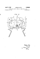
- FIG. 1 is a front elevation of the headrest or pillowof this invention, with a head support or net thereof partly cut away;
- FIG. 2 is a fragmental plan view of the headrest or pillow of this invention.
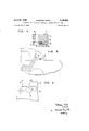
- FIGS. 3A and 3B are perspective views of the headrests or pillows according to this invention.
- FIG. 4 is a sectional View of a sspport block of this invention, the section being taken along the line IVIV I of FIG. 2;
- the headrest or I pillow is generally designated by the reference letter P and comprises a base B, support block S turnably mounted on the base B, a generally V-shaped arm A rigidly secured at one end thereof to the support block S, and a head support H.
- the base B is formed with a pair of horizontal extensions 1 each having a slot 2 serving to secure the base B to any suitable location behind a seat, for example, as shown in FIG. 5.
- a pair of upright support extensions 3 each having therein a horizontal slot 4, which is formed with several recesses 5 on the lower edge thereof as particularly shown in FIG. 6.
- the support block S comprises a pair of upper and lower block elements, S and S as particularly shown in FIG. 3A.
- the upper block element S has therein a vertical hole 6, which is in alignment with a hole 7 ver 3,189,683 Patented Apr. 27, 1965 "ice tically formed in the lower block element S as shown in FIGS. 1 and 4.
- the hole 7 has an enlarged portion 8 for receiving a head of a bolt which will hereinafter be described in detail.
- the upper block element S is also formed on the lower surface thereof with a horizontally extending lateral groove 9 of semi-circular cross section, which groove 9 is in registration with a similar groove 9 formed on the upper surface of the lower block element S and cooperates with the groove 9 to form a laterally extending hole 10 of circular cross-section through the block S.
- the upper and lower block elements S and S have in the lower and upper faces thereof, respectively, generally V-shaped grooves 11 and 11 of semi-circular cross-section, which grooves 11 and 11 face or are in registration with each other to form a generally V-shaped through hole 12 of circular cross-section in the support block S.
- This V-shaped hole 12 through the block S may be formed in a diverging fashion toward the head support H and surrounds the vertical holes 6 and 7.
- the bolt 13 includes an upper threaded portion 15 on which is screw-engaged a tightening nut 16 which cooperates with the thread of the portion 15 to tighten the upper and lower elements S and S against each other.
- the tightening bolt 13 is of hollow construction and internally threaded.
- An adjusting screw-rod 17 with a grip 13 is screw-engaged in the internal thread of the tightening bolt 13 and projects downwardly through the bolt 13 at 19 into abutting engagement with the upper face of the base as shown in FIG. 1.
- the adjusting screw-rod 17 may be displaced upwardly and downwardly through the tightening bolt 13 by manual operation of the grip 13.
- the support block S of the above described construction is mounted on the base B and is turnable about a horizontal axis.
- a pivot bolt N is passed through the laterally extending hole 10 formed from a pair of semicircular grooves 9 9 of the support blocks and through a pair of horizontal slots 4 in the upright support extensions 3 of the base B.
- the two ends of the pivot bolt 20 may rest in a pair of correspondingly opposite recesses 5 of the horizontal slots 4 of the extensions 3.
- the ends of the pivot bolt 20 are respectively provided with a head 21 and a threaded portion 22 on which is screwed a nut 23.
- the pivot bolt 20 is rigidly held to the extensions.
- the support block S is turnable about the longitudinal axis of the pivot bolt 20.
- the pivot bolt 2'8 is snugly inserted in the lateral hole 10 of the block S so that when the nut 23 is tightened against the extensions 3, the block S can be held in any inclined position with regard to the base B.
- the generally V-shaped arm A passes at the apex portion thereof through the generally V-shaped hole 12 of the block S and is rigidly held by the block as shown in FIG. 2.
- the arm A as is shown in FIG. 3A, extends from the block S and is provided at both free ends thereof with a pair of upright members 24 between which the head support H is bridged.
- the support H serves as a headrest.
- At the half-way portions of the V-shaped are A are formed a pair of arcuately curved portions 25, which serve as shock absorbing means for reducing any shock being transmitted to the head support H.
- the head support H and arm A may preferably be made of a net and a steel wire, respectively.
- the headrest or pillow P of this invention may be installed, for example, behind a seat of motor-vehicles as shown in FIG. 5, but it may be installed behind a seat of vehicles other than motor-vehicles.
- the assembly of theheadrest P of this invention may be carried out as follows. First, the lower block element S is placed on the base B between the upright extension 3 thereof. Then, the pivot bolt '26 is passed through the a 'pair of horizontal slots 4 of the extensions 3 and is placed in a suitable oppositely corresponding pair of the recesses 5. The V-shaped arm A is then placed at the apex portion thereof in the groove 11 of the element S and the groove 9 is applied to the pivot bolt 25. The upper block element S is then placed on the lower block element S with the groove 9 and 9 and the grooves 11 and 11 in registration with each other respectively to form the holes is and 12 and with the vertical holes 6 and 7 in alignment with each other. The tightening bolt 13 is then inserted into the.
- the tightening nut 16 is screw-engaged onto the bolt 13 to tighten the block elements S and S into one body.
- the .arm A and the pivot bolt 20 are rigidly held 'in the support block S.
- the nut 23 is applied onto the threaded portion 22 of the pivot bolt 2! and is loosely tightened.
- the adjusting screw-rod 17 is thereafter screwed into the internal thread of the tightening bolt 13 and is made to be projected downwardly so as to be brought into Contact with the upper face of the base B.
- the base B is secured to a suitable location, for example, as shown in FIG. 5, and the arm A with the head support or net H is turned or pivoted about the horizontal axis to a most suitable position for supporting the head of the, person sitting on the seat, by causing the adjusting screw-rod 17 to move upwardly or downwardly by operating the grip 18 thereof.
- the not 23 is then tightened against the upright extension 3 of the base.
- the arm A and therefore the head support H are fixed in an adjusted position.
- the adjustment of the position of the head support or net H may also be efiected by transrerring the pivot bolt 29 from an oppositely corresponding pair of recesses into another pair of recesses.
- the transfer of the pivot bolt 28 is carried out by loosening the nut 23.
- the headrest shownin FIG. 3A can be modified as shown in FIG. 3B, in which the like members as the FIG. 3A are designated by the like reference characters.
- the block elements S and S are elongated towards the arm A and the grip 18 and the nut 23 of the pivot bolt 20 are respectively formed as handle knobs.
- a headrest or pillow for vehicles, chairs and the like comprising a base, a horizontal pivot bolt carried on said base and turnable about its horizontal axis to be locked in any turning position, a support block consisting of a pile of upper and lower block elements detachably secured to each other, said upper block element having first and second grooves on the lower surface thereof, said lower block element having first and second grooves on the uppersurfacethereof, both said first and second grooves of the upper element and said first and second grooves of the lower element beingrespectively in registration with each other and cooperating to form first and second holes through said support block, said first holes snugly receiving said horizontal pivot bolt, an arm snugly received atone end thereof in said second hole of the block to be fixed thereto and extending substantially horizontally from said block, an adjusting.
Landscapes
- Engineering & Computer Science (AREA)
- Aviation & Aerospace Engineering (AREA)
- Transportation (AREA)
- Mechanical Engineering (AREA)
- Chair Legs, Seat Parts, And Backrests (AREA)
Description
April 1965 TAKEHISA SAlTO 3,180,683
HEADREST OR PILLOW FOR VEHICLES, CHAIRS AND THE LIKE Filed March 25, 1964 4 Sheets-Sheet 1 &
flaw we INVENTOR.
BY M83. OW
APril 1965 TAKEHISA SAlTO 3,180,683
HEADREST OR PILLOW FOR VEHICLES; CHAIRS AND THE LIKE Filed March 25, 1964 4 Sheets-Sheet 2 kca iu INVENTOR.
BY M
April 1965 TAKEHlSA SAITO HEADREST OR PILLOW FOR VEHICLES, CHAIRS AND THE LIKE Filed march 25, 1964 4 Sheets-Sheet 3 11am. s41;
INVENTOR- April 27, 1965 TAKEHISA SAITO HEADREST OR PILLOW FOR VEHICLES, CHAIRS AND THE LIKE Filed March 25, 1964 FIG. 4
s u? I2 I I2 idea 4 Sheets-Sheet 4 Rick.
INVENTOR.
United States Patent 3,180,683 HEADREST OR PILLOW FDR VEHICLES, CHAIRS AND THE LIKE Takehisa Saito, 1066 3-cl1ome, Kitsuki, Kawasaki-ski, Japan Filed Mar. 25, 1964, Ser. No. 354,626 Claims. (Cl. 297391) This invention relates to a headrest or pillow for vehicles, chairs and the like.
An extended driving of a motor-vehicle usually results in fatigue of the driver or other persons in the vehicle. However, if each rider could have a suitable headrest or pillow behind his seat for a more relaxed and comfortable posture, it would considerably and effectively reduce their fatigue. This is also true in case where a person sits on a seat other than that of a motor-vehicle.
The main object of this invention is to provide a headrest or pillow for vehicles, chairs and the like which will afford a comfortable sitting condition.
Another object of this invention is to provide a headrest or pillow which is simple in construction and easy to handle.
Another object of this invention is to provide a headrest or pillow capable of being assembled by an easy procedure.
Still another object of this invention is to provide a headrest or pillow which can easily be adjusted in its position to give the most comfortable condition.
A further object of this invention is to provide a headrest or pillow which will not allow shocks or vibrations to be transmitted to the head support member thereof.
The above and other objects and advantages of this invention will become apparent as the description proceeds, in connection with the accompanying drawings, in which the like parts are designated by the like reference characters, and in which:
FIG. 1 is a front elevation of the headrest or pillowof this invention, with a head support or net thereof partly cut away;
FIG. 2 is a fragmental plan view of the headrest or pillow of this invention;
FIGS. 3A and 3B are perspective views of the headrests or pillows according to this invention;
FIG. 4 is a sectional View of a sspport block of this invention, the section being taken along the line IVIV I of FIG. 2;
Referring now to FIGS. 1, 2 and 3A, the headrest or I pillow according to this invention is generally designated by the reference letter P and comprises a base B, support block S turnably mounted on the base B, a generally V-shaped arm A rigidly secured at one end thereof to the support block S, and a head support H.
The base B is formed with a pair of horizontal extensions 1 each having a slot 2 serving to secure the base B to any suitable location behind a seat, for example, as shown in FIG. 5. On both sides of the base B are provided a pair of upright support extensions 3 each having therein a horizontal slot 4, which is formed with several recesses 5 on the lower edge thereof as particularly shown in FIG. 6.
The support block S comprises a pair of upper and lower block elements, S and S as particularly shown in FIG. 3A. The upper block element S has therein a vertical hole 6, which is in alignment with a hole 7 ver 3,189,683 Patented Apr. 27, 1965 "ice tically formed in the lower block element S as shown in FIGS. 1 and 4. The hole 7 has an enlarged portion 8 for receiving a head of a bolt which will hereinafter be described in detail. The upper block element S is also formed on the lower surface thereof with a horizontally extending lateral groove 9 of semi-circular cross section, which groove 9 is in registration with a similar groove 9 formed on the upper surface of the lower block element S and cooperates with the groove 9 to form a laterally extending hole 10 of circular cross-section through the block S. The upper and lower block elements S and S have in the lower and upper faces thereof, respectively, generally V- shaped grooves 11 and 11 of semi-circular cross-section, which grooves 11 and 11 face or are in registration with each other to form a generally V-shaped through hole 12 of circular cross-section in the support block S. This V-shaped hole 12 through the block S may be formed in a diverging fashion toward the head support H and surrounds the vertical holes 6 and 7.
Through the holes 6 and 7 of the block S passes a tightening bolt 13 the lower end of which has a head 14 received on the enlarged portion 8 of the hole 7 as shown in FIG. 1. The bolt 13 includes an upper threaded portion 15 on which is screw-engaged a tightening nut 16 which cooperates with the thread of the portion 15 to tighten the upper and lower elements S and S against each other. The tightening bolt 13 is of hollow construction and internally threaded. An adjusting screw-rod 17 with a grip 13 is screw-engaged in the internal thread of the tightening bolt 13 and projects downwardly through the bolt 13 at 19 into abutting engagement with the upper face of the base as shown in FIG. 1. Thus, the adjusting screw-rod 17 may be displaced upwardly and downwardly through the tightening bolt 13 by manual operation of the grip 13.
The support block S of the above described construction is mounted on the base B and is turnable about a horizontal axis. A pivot bolt N is passed through the laterally extending hole 10 formed from a pair of semicircular grooves 9 9 of the support blocks and through a pair of horizontal slots 4 in the upright support extensions 3 of the base B. The two ends of the pivot bolt 20 may rest in a pair of correspondingly opposite recesses 5 of the horizontal slots 4 of the extensions 3. The ends of the pivot bolt 20 are respectively provided with a head 21 and a threaded portion 22 on which is screwed a nut 23. When the nut 23 is screw-tightened against the upright extension 3 of the base B, the pivot bolt 20 is rigidly held to the extensions. Thus, the support block S is turnable about the longitudinal axis of the pivot bolt 20.
, The pivot bolt 2'8 is snugly inserted in the lateral hole 10 of the block S so that when the nut 23 is tightened against the extensions 3, the block S can be held in any inclined position with regard to the base B.
The generally V-shaped arm A passes at the apex portion thereof through the generally V-shaped hole 12 of the block S and is rigidly held by the block as shown in FIG. 2. The arm A, as is shown in FIG. 3A, extends from the block S and is provided at both free ends thereof with a pair of upright members 24 between which the head support H is bridged. The support H serves as a headrest. At the half-way portions of the V-shaped are A are formed a pair of arcuately curved portions 25, which serve as shock absorbing means for reducing any shock being transmitted to the head support H. The head support H and arm A may preferably be made of a net and a steel wire, respectively.
The headrest or pillow P of this invention may be installed, for example, behind a seat of motor-vehicles as shown in FIG. 5, but it may be installed behind a seat of vehicles other than motor-vehicles.
The assembly of theheadrest P of this invention may be carried out as follows. First, the lower block element S is placed on the base B between the upright extension 3 thereof. Then, the pivot bolt '26 is passed through the a 'pair of horizontal slots 4 of the extensions 3 and is placed in a suitable oppositely corresponding pair of the recesses 5. The V-shaped arm A is then placed at the apex portion thereof in the groove 11 of the element S and the groove 9 is applied to the pivot bolt 25. The upper block element S is then placed on the lower block element S with the groove 9 and 9 and the grooves 11 and 11 in registration with each other respectively to form the holes is and 12 and with the vertical holes 6 and 7 in alignment with each other. The tightening bolt 13 is then inserted into the. vertical holes 6 and 7, and the tightening nut 16 is screw-engaged onto the bolt 13 to tighten the block elements S and S into one body. Thus, the .arm A and the pivot bolt 20 are rigidly held 'in the support block S. The nut 23 is applied onto the threaded portion 22 of the pivot bolt 2!) and is loosely tightened. The adjusting screw-rod 17 is thereafter screwed into the internal thread of the tightening bolt 13 and is made to be projected downwardly so as to be brought into Contact with the upper face of the base B.
In use, the base B is secured to a suitable location, for example, as shown in FIG. 5, and the arm A with the head support or net H is turned or pivoted about the horizontal axis to a most suitable position for supporting the head of the, person sitting on the seat, by causing the adjusting screw-rod 17 to move upwardly or downwardly by operating the grip 18 thereof. The not 23 is then tightened against the upright extension 3 of the base. Thus, the arm A and therefore the head support H are fixed in an adjusted position.
The adjustment of the position of the head support or net H may also be efiected by transrerring the pivot bolt 29 from an oppositely corresponding pair of recesses into another pair of recesses. The transfer of the pivot bolt 28 is carried out by loosening the nut 23. Thus, the adjustment of the position of the head support H is possible in the direction of the arm A, as well as the pivotal adjustment thereof. The headrest shownin FIG. 3A can be modified as shown in FIG. 3B, in which the like members as the FIG. 3A are designated by the like reference characters. In the embodiment of FIG. 3B, the block elements S and S are elongated towards the arm A and the grip 18 and the nut 23 of the pivot bolt 20 are respectively formed as handle knobs.
While preferred embodiments of the present invention have been shown and described, it is of course, to be understood that this invention is not limited to the embodiment shown, but can be modified without departing from the spirit and scope of the invention as set forth in th,
appended claims.
What I claim is: 1. A headrest or pillow for vehicles, chairs and the like, comprising a base, a horizontal pivot bolt carried on said base and turnable about its horizontal axis to be locked in any turning position, a support block consisting of a pile of upper and lower block elements detachably secured to each other, said upper block element having first and second grooves on the lower surface thereof, said lower block element having first and second grooves on the uppersurfacethereof, both said first and second grooves of the upper element and said first and second grooves of the lower element beingrespectively in registration with each other and cooperating to form first and second holes through said support block, said first holes snugly receiving said horizontal pivot bolt, an arm snugly received atone end thereof in said second hole of the block to be fixed thereto and extending substantially horizontally from said block, an adjusting. screw-rod extending substantially vertically through said support block in screwengagernent therewith'so as to be adjusted in its position in relation to said support block with the lower end of the rod in abutting engagement with the upper face of said base and with the upper end of the rod projecting from said block to enable the operation of the rod, said adjusting screw-rod lying out biplanes including said pivot bolt, and ahead support member secured to the free end of said arm. V
2. A headrest or ,illow according to claim 1, wherein said upper and lower block elements of the support block are detachably secured by means of a bolt nut assembly extending vertically therethrough, and said adjusting screw-rod passes through said bolt-nut assembly longitudinally thereof.
3. A headrest or pillow according to claim 1, wherein said second hole of the support block is formed in V- shaped configuration and said arm is also formed in ti-shaped configuration so as to conform to the hole, and wherein said head support member extends between the free endsof the arm. 7
4. A headrest or pillow, according to claim 3, wherein said arm has at midway parts thereof arcuately curved portions. 7
5. A headrest or pillow according to claim 1, wherein said support block isdisplaceable in relation to said base in the longitudinal direction. of said arm.
References ited by the Examiner UNITED ST TES PATENTS 69,135 9/ 67 Snowden 297-409 171,539 12/75 Starr 297-409 236,212 1/ 8 1 Cartwright 2974(l2 373,142 11/87 Koenig z 297393 2,101,973 8/63' Toth 297-391 FOREIGN PATENTS 831,322 9/56 Great Britain.
' FRANK B; SHERRY, Primary Examiner.
Claims (1)
1. A HEADREST OR PILLOW FOR VEHICLES, CHAIRS AND THE LIKE, COMPRISING A BASE, A HORIZONTAL PIVOT BOLT CARRIED ON SAID BASE AND TURNABLE ABOUT ITS HOTIZONTAL AXIS TO BE LOCKED IN ANY TURNING POSITION, A SUPPORT BLOCK CONSISTING OF A PILE OF UPPER AND LOWER BLOCK ELEMENTS DETACHABLY SECURED TO EACH OTHER, SAID UPPER BLOCK ELEMENT HAVING FIRST AND SECOND GROOVES ON THE LOWER SURFACE THEREOF, SAID LOWER BLOCK ELEMENT HAVING FIRST AND SECOND GROOVES ON THE UPPER SURFACE THEREOF, BOTH SAID FIRST AND SECOND GROOVES OF THE UPPER ELEMENT AND SAID FIRST AND SECOND GROOVES OF THE LOWER ELEMENT BEING RESPECTIVELY IN REGISTRATION WITH EACH OTHER AND COOPERATING TO FORM FIRST AND SECOND HOLE THROUGH SAID SUPPORT BLOCK, SAID FIRST HOLES SNUGLY RECEIVING SAID HORIZONTAL PIVOT BOLT, AN ARM SNUGLY RECEIVED AT ONE END THEREOF IN SAID SECOND HOLE OF THE BLOCK TO BE FIXED THERETO AND EXTENDING SUBSTANTIALLY HORIZONTALLY FROM SAID BLOCK, AN ADJUSTING SCREW-ROD EXTENDING SUBSTANTIALLY VERTICALLY THROUGH SAID SUPPORT BLOCK IN SCREWENGAGEMENT THEREWITH SO AS TO BE ADJUSTED IN ITS POSITION IN RELATION TO SAID SUPPORT BLOCK WITH THE LOWER END OF THE ROD IN ABUTTING ENGAGEMENT WITH THE UPPER FACE OF SAID BASE AND WITH THE UPPER END OF THE ROD PROJECTING FROM SAID BLOCK TO ENABLE THE OPERATION OF THE ROD, SAID ADJUSTING SCREW-ROD LYING OUT OF PLANES INCLUDING SAID PIVOT BOLT, AND A HEAD SUPPORT MEMBER SECURED TO THE FREE END OF SAID ARM.
Priority Applications (1)
| Application Number | Priority Date | Filing Date | Title |
|---|---|---|---|
| US354626A US3180683A (en) | 1964-03-25 | 1964-03-25 | Headrest or pillow for vehicles, chairs and the like |
Applications Claiming Priority (1)
| Application Number | Priority Date | Filing Date | Title |
|---|---|---|---|
| US354626A US3180683A (en) | 1964-03-25 | 1964-03-25 | Headrest or pillow for vehicles, chairs and the like |
Publications (1)
| Publication Number | Publication Date |
|---|---|
| US3180683A true US3180683A (en) | 1965-04-27 |
Family
ID=23394213
Family Applications (1)
| Application Number | Title | Priority Date | Filing Date |
|---|---|---|---|
| US354626A Expired - Lifetime US3180683A (en) | 1964-03-25 | 1964-03-25 | Headrest or pillow for vehicles, chairs and the like |
Country Status (1)
| Country | Link |
|---|---|
| US (1) | US3180683A (en) |
Cited By (3)
| Publication number | Priority date | Publication date | Assignee | Title |
|---|---|---|---|---|
| FR2420444A1 (en) * | 1978-03-24 | 1979-10-19 | Aisin Seiki | HEADREST ADJUSTING DEVICE |
| FR2551707A1 (en) * | 1983-09-10 | 1985-03-15 | Daimler Benz Ag | HEADREST HAVING AT LEAST ONE CARRIER ARM IN A MOTOR VEHICLE |
| EP0101073A3 (en) * | 1982-08-12 | 1985-09-18 | Audi Nsu Auto Union Aktiengesellschaft | Motor car with tiltable rear seat and adjustable head rests |
Citations (6)
| Publication number | Priority date | Publication date | Assignee | Title |
|---|---|---|---|---|
| US69135A (en) * | 1867-09-24 | Henry snowpen | ||
| US171539A (en) * | 1875-12-28 | Improvement in head-rests for dental chairs | ||
| US236212A (en) * | 1881-01-04 | Eobeet oaetweight | ||
| US373142A (en) * | 1887-11-15 | Head-rest | ||
| US2101973A (en) * | 1935-02-11 | 1937-12-14 | Maschf Augsburg Nuernberg Ag | Double walled sluice gate |
| GB831322A (en) * | 1955-10-08 | 1960-03-30 | Dunlop Rubber Co | Improvements relating to upholstered structures |
-
1964
- 1964-03-25 US US354626A patent/US3180683A/en not_active Expired - Lifetime
Patent Citations (6)
| Publication number | Priority date | Publication date | Assignee | Title |
|---|---|---|---|---|
| US69135A (en) * | 1867-09-24 | Henry snowpen | ||
| US171539A (en) * | 1875-12-28 | Improvement in head-rests for dental chairs | ||
| US236212A (en) * | 1881-01-04 | Eobeet oaetweight | ||
| US373142A (en) * | 1887-11-15 | Head-rest | ||
| US2101973A (en) * | 1935-02-11 | 1937-12-14 | Maschf Augsburg Nuernberg Ag | Double walled sluice gate |
| GB831322A (en) * | 1955-10-08 | 1960-03-30 | Dunlop Rubber Co | Improvements relating to upholstered structures |
Cited By (3)
| Publication number | Priority date | Publication date | Assignee | Title |
|---|---|---|---|---|
| FR2420444A1 (en) * | 1978-03-24 | 1979-10-19 | Aisin Seiki | HEADREST ADJUSTING DEVICE |
| EP0101073A3 (en) * | 1982-08-12 | 1985-09-18 | Audi Nsu Auto Union Aktiengesellschaft | Motor car with tiltable rear seat and adjustable head rests |
| FR2551707A1 (en) * | 1983-09-10 | 1985-03-15 | Daimler Benz Ag | HEADREST HAVING AT LEAST ONE CARRIER ARM IN A MOTOR VEHICLE |
Similar Documents
| Publication | Publication Date | Title |
|---|---|---|
| US4634178A (en) | Adaptable seating device | |
| US5171063A (en) | Helm chair | |
| US4097087A (en) | Chair with adjustable back support cushion | |
| US4425863A (en) | Pendulum helmsman seat | |
| US2815517A (en) | Rowing device | |
| US5140914A (en) | Vehicle seat tray | |
| EP0941679B1 (en) | Rocking and gliding mechanism | |
| US3246347A (en) | Combination seat and bed | |
| US3163409A (en) | Torsion bar seat suspension | |
| US2937694A (en) | Tray assembly for attachment to a wheelchair | |
| US1744364A (en) | Headrest | |
| US2897878A (en) | Removable head rest for vehicles | |
| US3387886A (en) | Automobile headrest | |
| US5137249A (en) | Outboard motor mount for canoe | |
| US2869146A (en) | Automobile seat attachment for dogs | |
| US2195507A (en) | Motor vehicle | |
| US4950004A (en) | Bicycle chair | |
| US4502727A (en) | Pivot mounted cycle seat with spring cradle | |
| US3990743A (en) | Back support assembly for boat seats | |
| US4672911A (en) | Canoe seat and oar lock unit | |
| US3709535A (en) | Hinge iron for posture chair | |
| EP0179224A3 (en) | Arrangement of a pneumatic spring, particularly for the backrest support of an office chair | |
| US3107942A (en) | Infant's seat | |
| KR102551507B1 (en) | Back rest for motorcycle | |
| US2710758A (en) | Mechanic's creeper with adjustable headrest |