US3180254A - Tag marking machine - Google Patents
Tag marking machine Download PDFInfo
- Publication number
- US3180254A US3180254A US291019A US29101963A US3180254A US 3180254 A US3180254 A US 3180254A US 291019 A US291019 A US 291019A US 29101963 A US29101963 A US 29101963A US 3180254 A US3180254 A US 3180254A
- Authority
- US
- United States
- Prior art keywords
- machine
- hopper
- platen
- tags
- tag
- Prior art date
- Legal status (The legal status is an assumption and is not a legal conclusion. Google has not performed a legal analysis and makes no representation as to the accuracy of the status listed.)
- Expired - Lifetime
Links
Images







Classifications
-
- B—PERFORMING OPERATIONS; TRANSPORTING
- B65—CONVEYING; PACKING; STORING; HANDLING THIN OR FILAMENTARY MATERIAL
- B65H—HANDLING THIN OR FILAMENTARY MATERIAL, e.g. SHEETS, WEBS, CABLES
- B65H3/00—Separating articles from piles
- B65H3/24—Separating articles from piles by pushers engaging the edges of the articles
Definitions
- This invention relates to price marking machines which are utilized to print prices and other information upon tags, tickets and labels.
- the machine of this invention is capable of handling, i.e., feeding, printing and dispensing, a variety of different types of tags, tickets and labels, including those provided in continuous strip form and those provided as individual entities.
- the invention is disclosed primarily in relation to those features of the machine which are especially adapted for use in the handling of ready-towear tags.
- An identifying characteristic of these tags isthat they are made up of one, two, three or more parts, with each part being adapted to carry a considerable amount of information in addition to price, and in the case of multi-part tags, each part repeating at least a substantial part of the information, if not all.
- tags carry coded information and printed information. Not all of the coded information need be printed upon the tag, but there is a desirable minimum of printing which has to be directly readable by store personnel and even this is considerable.
- the punched code information is applied by other machines.
- the machine of this invention is concerned only with the application of printed information.
- the multi-part marking tags which are utilized in the machine of this invention comprise parts which are defined one from the other by serrated lines along which the parts are adapted to be torn one from the other at the time of a sale.
- One part of the tag is designed to remain with the garment as it goes into the hands of the purchaser to be used as identification in the event of a return of the garment.
- a second part may be desired for inventory control purposes.
- a third part may be desired for billing purposes.
- a fourth part may be desired by a department head or a buyer.
- the demand for different numbers of parts of individual tags may vary from depart ment to department and from store to store.
- a further objective has been to provide a machine in which changes in the information to be printed upon the tags of different runs can be made rapidly and with a minimum of efiort.
- a typical marking machine provision is made to hold a supply of tags, there is a printing head and some means to ink the printing head, and there is also a mechanism to feed the tags from the supply to the printing head and then to a dispensing point.
- this requires three mechanisms-feeding, printing, and inking.
- these mechanisms have been individual systems of parts.
- these individual systems In small machines, these individual systems have been adapted to be synchronized by utilizing simple interlinkages.
- the individual systems of parts in the past, have required complex driving mechanisms and interconnecting linkages to insure correct sequence of operations and proper timing.
- Another one of the objectives of this invention has been to simplify what has been in the past a complex system of mechanisms and parts designed to fulfill the demands that are placed upon a machine of the readyto-wear type, and to relate them in such a way that the three basic operations of feeding, printing, and inking are powered from one shaft, with this shaft being timed so that it makes one revolution for each part of a multi-part tag that is to be processed.
- Tags of this sort pose special problems in a marking machine because the strings tend to become entangled and in the stacking of a number of these tags in a hopper, the ends to which the strings are attached stack higher than the ends having no strings on them. This latter problem increases with the height of the stack. A differential in the heights of the two sides of a stack is not particularly noticeable when only three or four tags are in the stack. When the stack is higher the problem becomes more acute, and it may beseen that as the tags are fed frorn the stack the problem of changing stack condition arises.
- Another objective of the invention has been to provide a marking machine in which provision is made to handle large stacks of string tags without entangling and in which provision is made to compensate for the differences in the heights of the two sides of a stack even under changing conditions.
- FIGURE 1 is a front elevational view of a tag marking machine incorporating the principles of this invention.
- FIGURE 2 is a perspective view showing the side of themachine with the cover removed in order to show the driving mechanism.
- FIGURE 3 is a fragmentary plan view of the top of the machine with the printing head removed and illustrating the tag feed mechanism.
- FIG. 4 is an enlarged, fragmentary side elevational view of the machine with the cover removed illustrating details a of the driving mechanism. In this view the various parts of the machine are shown in the home position.
- FIGURE 5 is a view similar to FIGURE 4 in which the various parts of the machine have progressed from the home position in a tag feeding part of the cycle.
- FIGURE 6 is a view similar to FIGURE 4 showing the parts in an advanced position in which the printing head is being inked.
- FIGURE 7 is a view similar to FIGURE 4 showing the parts approaching a position in one cycle in which the ink pad of the machine is to be inked.
- FIGURE 8 is a view similar to FIGURE 4 showing inking pad in a position in which it receives a new charge of ink. This figure illustrates the positions of the various parts of the machine just prior to their return to the condition of FIGURE 4 which is the home position and which designates the end of one cycle of operation.
- FIGURE 9 is a fragmentary cross sectional view taken on the line 9-9 of FIGURE 3.
- FIGURE 10 is a fragmentary cross-sectional view taken on the line 10-10 in FIGURE 4.
- FIGURE 11 is a fragmentary cross-sectional view taken on the line 11I1 of FIGURE 10.
- FIGURE 12 is a fragmentary cross-sectional View taken on the line 12-12 of FIGURE 11.
- FIGURE 13 is a fragmentary cross-sectional view taken on the line 1313 of FIGURE 11.
- FIGURE 14 is a fragmentary cross-sectional view taken on the line 1414 of FIGURE 11.
- FIGURE 15 is a fragmentary cross-sectional view taken on the line 1515 of FIGURE 10.
- FIGURE 16 is a fragmentary view taken on a plane which passes through the machine just above the hopper, which is designed to receive the tags, and illustrating a gate mechanism.
- FIGURE 17 is a view similar to FIGURE 16 illustrating the gate mechanism in a partially open condition.
- FIGURE 18 is a view similar to FIGURES 16 and 17 showing the gate in a fully opened position.
- FIGURE 19 is a fragmentary cross-sectional view looking at the underside of the ink pad carrier and its associated mechanism.
- FIGURE 20 is a fragmentary elevational view illustrating the platen in the machine upon which the tags are printed.
- FIGURE 21 is an enlarged cross-sectional view taken on the line Z1-2I of FIGURE 20 and illustrating the feed finger mechanism in its retracted position.
- FIGURE 22 is a view similar to FIGURE 21 illustrating the feed finger mechanism in an advanced position.
- FIGURE 23 is an enlarged cross-sectional view taken on the line 2323 of FIGURE 3 and illustrating the inking pad and its associated mechanism.
- FIGURE 24 is a view similar to FIGURE 23 illustrating the inking pad and its associated mechanism in that FIGURE 25 is a view similar to FIGURE 23 in which the feed finger and its associated parts are in positions to apply a charge of ink to the type of the printing head.
- FIGURE 26 is a fragmentary cross-sectional view taken on the line 2626 of FIGURE 4.
- FIGURE 1 shows the front of a marking machine embodying the principles of this invention.
- the housing of the machine is designated generally by the numeral 1. Following conventional practices, this housing may consist of a number of removable sections in order to provide access to the interior of the machine.
- a printing head assembly is shown generally at 2,. The specific construction of the printing head forms no part of the present invention. Generally, however, as shown, the printing head comprises two sets of fifteen individual flexible bands each band of which is identified at 3. In each set, the bands are arranged side-by-side and each band has printing characters on it. These printing characters may be selectively brought into printing position by means of a combined band selector and band rotating device, indicated generally by the numeral 4 which is provided for each set.
- Each band is divided into a lower sector carrying the printing characters which are arranged in sequence along the band and a plurality of readable characters which are arranged in the same sequence as the printing characters along the upper sector of the band.
- a stack of multi-part tags are placed in the machine so that as viewed in FIGURE 1, the heads of the tags are toward the left and the bottom of the tags are toward the right.
- the two sets of printing bands are designed to print two lines of characters which read from the top toward the bottom on each part of the tag.
- a price line printing unit 6 which preferably also has printing bands in it simliar to those in the printing head assembly, which are arranged to print price marking indicia across the foot of each part of the multi-part tags.
- the machine illustrated has an on-ofi, master switch 7 and an indicator light 8 which comes 'on when switch 7 is on. Controls are provided for the machine including a start switch 9, and a stop switch 10. Stop switch 10 comprises a manual stop. There are in addition, two automatic stops one of which is controlled by a counter 11 and the other of which, to be described later, becomes effective when the last tag of a stack is fed from the machine.
- Counter 11 is similar to that type disclosed in United States Patent No. 2,622,804 which may be preset to a selected number, corresponding to the number of tags to be run. The counter is arranged such that it counts backwards from a preselected number toward zero and when reaching zero, functions to decommission the machine.
- One cycle of the machine consists of the feeding and printing of one part of a multi-part tag.
- provision must be made to preset the machine for operation with tags of various widths or parts.
- a knob to control such mechanism is shown at the front of the machine at 12. Four positions for this knob are shown corresponding to single width, two part, three part, and four part tag operations, plus an ofi? position.
- This preset knob is used in conjunction with reset knob 13.
- the operation and interconnections of the counter, the control knob and the reset knob are disclosed in United States patent application Serial No. 346,240 filed February 20,1964. For the present purposes, however, it is sufiicient to state that the control knob 12 determines the complete tag count shown on the counter.
- the counter 11 makes one count for each cycle of the machine.
- the counter makes one count for each two cycles.
- the counter makes one count for each three cycles of the machine and so on, so that the counter does not tally cycles but tallies of the machine and it comprises two side walls 1616 and a wall 1'7 that is curved for'the sake of appearance and that constitutes both a back and a top wall.
- the forward portion'of wall 17, at the top of theframe member, is cut out as at 13 to accommodate a journal sleeve 19 that is an integral part of a hopper-platenassembly designated generally by the numeral Ztl.
- Journal sleeve 19 is pivotally mounted upon a shaft 21, the ends of which are appropriately journalled in the upper portion of the two side walls 16 of frame member 15. As shown in FIGURE 2, the forward part of the side walls are reinforced by added metal. In addition, following known practices, all frame members may have'ri'os in order to strengthen them in crucial areas and appropriate flanges are provided in order to bolt the frame members to base plate 14.
- FIGURE 3 Another one of the. three outer frame members is shown at 22 in FIGURE 3. This is the largest oneof the frame members and it is well stressed, using known techniques, because it carries a bracket 23 which mounts the printing head 2 in cantilever fashion.
- the third outer frame member is shown at 24- and it is centered at the front of the machine.
- the fourth cast frame member is shown in FIGURE 2 at Ma and it provides a support for drive and control members as will be' explained. Following known techniques, the three outer frame members are joined by removable cover plates which protect the working parts of the machine and which add to the overall appearance of the machine.
- the hopper-platen assembly 2'1 is pivotally mounted at the rear on shaft 21 for a rocking movement in which its front end has limited up and down swinging movement.
- the printing head is stationary and tickets to be printed are carried by the assembly up into a position in which they are impressed by the type carried by the printing head.
- the hopper platen assembly comprises generally a table 25 at the. top over which labels and tags in strip form are adapted to be feditoward the printing head, a hopper designated generally 26, which is toward the front of the assembly and in which readyto-wear tickets are placed, and a platen 27 on which the to the journal sleeve 19 at the' rear as shown in dotted lines in FIGURES 4-8.
- the forward end of the boxlike casting 28 is closed by a wall 31, and the top is closed by a plate 32, which is appropriately bolted in place to the frame, this plate forming part of table 25.
- Bottom wall 29 and forward wall'31 are best illustrated in FIGURES 11 and 14.
- the two side walls 30-39 are best illustrated in FIGURES 14 and 16-18; As will be seen, the forward wall 31 is at the back of hopper 26. There is in addition an extension ,of the side wall of casting 28 at the right. This extension is designated 33 and may best be seen in FIGURES 9, 10, 13, 16 and 18, it is offset outwardly, as at 34, toward the right from side wall 30 in order to accommodatefhopper 26 and in addition it depends belowthe bottom wall 29 in order to provide support for mechanism at the forward end of the assembly, as will be explained.
- a hollow box-like casting 35 is secured to the forward 6 to be printed slide as they are fed onto the platen.
- the left side of the hopper-platen assembly carries a plate 42 which is cut out as shown at 43 in FIGURE 2 to expose the hopper 26.
- the plate 42 extends forwardly under the platen and at the front of the hopper it is secured bymeans such as bolts to a seat 44 machined in the side of casting 35 as may be seen in FIGURES 16 and 17.
- plate 42 covers the casting 28 being removably secured to it for maintenance and adjustment pur-" poses by means of machine screws.
- the forward wall 31 of casting 28 is coextensive with a back wall 45 of the hopper 26.
- Wall 45 is also coextensive with a wall 46 which forms the right side of the hopper, this wall being secured to the extension 33 in the area thereof to the rear of the box-like casting 35 that forms the forward end of the hopper-platen assembly.
- the upper part of right wall 46 extends forwardly beyond the hopper area to provide the guide strip 41 to which reference has been made.
- the extension of the wall 46 is best seen in FIGURE 18.
- the front side of the hopper is defined by a vertical wall 47 which is fastened by means such as machine screws to the rear of the box-like casting 35. This is best shown in FIGURES 10 and 12.
- the wall 47 extends downwardly considerably below the casting 35 and its lower edge is substantially V-shaped.
- Wall 47 also has a vertical slot 4:; which extends substantially the full height of the wall, the purpose'of this slot to be explained later.
- the bottom wall of the hopper is formed by a plate 49 which is fastened to a flange 50 turned over at a right angle from the lower edge of wall 46 at one side thereofand fastened to a right angular flange 51 at the other side edge thereof. The latter right angular flange is secured to the plate 42 which extends along the left face of the hopper-platen assembly.
- Tickets within the hopper are held against the forward wall 47 by means of a pusher plate 52 which is adjustable from the front to the rear of the hopper into any one of four positions so as to accommodate tickets having from one to four different parts.
- the upper part of pusher plate 52 is turned over at a right angle to provide a rearward extension 53 that passes through a slot 54 at the upper edge of forward wall 31 of the box-like casting 28 to immediately underlie the'plate 32 that constitutes a table.
- plate 32 is removed in FIGURE 18, it can be seen that the extension 53 c'onstitutes an extension of the table on which tags and labels in strip form may be fed toward the platen from the rear of the machine.
- A'spring urged latch member 55 iscarried at the top of the pusher plate 52 and its function is to hold the upper,- most one of a stack of tickets within the hopper from being pulled to the rear during the retracting movement of the feed fingers of the machine which are to be described later. projects through a rectangular opening 56 at thetop. of the pusher plate 52 and it is turned over toward the front of the machine to provide -a thin edge 57 which rests on top of the uppermost ticket within the hopper.
- a large headed rivet 58 which is fastened to the pusher plate 52 adjacent to its upper edge passes through a slot 59 in latch member'SS to hold it in place while permitting'a slight amount of vertical movement for this member;
- the lower end of latch member 55 straddles the upper end'of acast block 60 and a small coil spring 61 seated in a bore at the top of block 60 I normally urges the latch member 55 into the elevated 37 which is toward the right as viewed from the front may I .be secured by means such as'bolts to the extension 33 or .it may be cast as an integral part of it.
- the upper surface in this figure, casting 35 has a slot init to accommodate the forward end of a guide strip 41 against which tickets their movement, it being assumed that when strips are being fed notickets would be in the hopper to hold the latch member in the elevated position shown.
Landscapes
- Engineering & Computer Science (AREA)
- Mechanical Engineering (AREA)
- Sheets, Magazines, And Separation Thereof (AREA)
Description
April '27, 1965 Filed June 27, 1963 P. H. HAMISCH, SR
TAG MARKING MACHINE 17 Sheets-Sheet l RESET A ril 27, 1965 P. H. HAMISCH, SR 3,180,254
TAG MARKING MACHINE Filed June 27, 1963 1}? Sheets-Sheet 2 Q Q m3 1..
INVENTOR. m 2:. BY
M W? M H'ITQRMEYS April 7, 1965 P. H. HAMISCH, SR 3,180,254
TAG MARKING MACHINE Filed June 27, 1965 1'7 Sheets-Sheet 3 INVENTOR.
%JX4 MMYW April 27, 1965 P. H. HAMISCH, sR
TAG MARKING MACHINE l7 Sheets-Sheet 4 Filed June 27, 1963 INVENTOR. 24 MA.
M M i 8444 w BY April 1965 P. H. HAMISCH, SR 3,180,254
TAG mama MACHINE Filed June 27, 1963 17 Sheets-Sheet 5 INVENTOR.
M M g/M April 1965 P. H. HAMISCH, SR 3,180,254
TAG MARKING MACHINE l7 Sheets-Sheet 6 Filed June 27, 1963 INVENTOR.
April 27, 1965 P. H. HAMISCH, sR 3,180,254
me MARKING MACHINE Filed June 27, 1963 17 Sheets-Sheet 7 INVENTOR.
hop,
mxms.
April 27, 1965 P. H. HAMISCH, SR
me MARKING MACHINE 17 Sheets-Sheet 8 Filed June 27, 1963 April 1965 P. H. HAMISCH, 512 3,180,254
TAG MARKING MACHINE Filed June 27, 1965 17 Sheets-Sheet 9 &
INVENTOR.
April 27, 1965 Filed June 27, 1963 P. H. HAMISCH, SR
TAG MARKING MACHINE 17 Sheets-Sheet l0 ATTORNEYS.
April 27, 1965 P. H. HAMISCH, SR
TAG MARKING MACHINE l7 Sheets-Sheet 11 Filed June 27, 1963 INVENTOR.
P. H. HAMISCH, SR
TAG MARKING MACHINE l7 Sheets-Sheet 12 Filed June 27, 1963 il/III a w W I 7/// Q i H Q In x a a 4 4 0 2 O H. w w lu .1 I: A a m: W a J I-Jl 1 9 a a. v w w a 7 2 U A 3 H w ill 2/ Z N "w ."w .w M 4 w w INVENTOR.
H77'ORN EYS A ril 27, 1965 P. H. HA iscH; s
'TAG MARKING MACHINE Filed June 27, 1963 17 Sheets-'Shegi 1s o am April 1965 P. H. HAMISCH, SR 3,180,254 TAG MARKING MACHINE Filed June 27, 1963 17 Sheets-Sheet 14 INVENTOR. FM/i4 M/KMWY/W A ril 27, 1965 P HAMISCH, sR
" no MARKING momma 17 Sheets- Sheet 16 Filed June 27, 1963' INVENTOR. Z My.
v M am A FORMEYS April 27, 1965 P. H. HAMISCH, SR
TAG MARKING MACHINE 17 Sheets-Sheet 17 Filed June 27, 1963 HTTORNEYS United States Patent 3,180,254 TAG MARKING MACHINE Paul H. Hamisch, Sn, Dayton, Ohio, assignor to The Monarch Marking System Company, Dayton, Ohio, a corporation of Ohio Filed June 27, 1963, Ser. No. 291,019 8 Claims. (Cl. 101-69) This invention relates to price marking machines which are utilized to print prices and other information upon tags, tickets and labels. The machine of this invention is capable of handling, i.e., feeding, printing and dispensing, a variety of different types of tags, tickets and labels, including those provided in continuous strip form and those provided as individual entities. However, inasmuch as the demands placed upon the machine are greatest in the handling of those individual tags utilized in the ready-towear garment trade, the invention is disclosed primarily in relation to those features of the machine which are especially adapted for use in the handling of ready-towear tags. An identifying characteristic of these tags isthat they are made up of one, two, three or more parts, with each part being adapted to carry a considerable amount of information in addition to price, and in the case of multi-part tags, each part repeating at least a substantial part of the information, if not all.
The use of data processing machines in the inventory, billing and other departments of stores has led to the use of coding systems, such as punched codes, readable by these processing machines. Thus, in many instances the tags carry coded information and printed information. Not all of the coded information need be printed upon the tag, but there is a desirable minimum of printing which has to be directly readable by store personnel and even this is considerable. The punched code information is applied by other machines. The machine of this invention is concerned only with the application of printed information.
The multi-part marking tags which are utilized in the machine of this invention comprise parts which are defined one from the other by serrated lines along which the parts are adapted to be torn one from the other at the time of a sale. One part of the tag is designed to remain with the garment as it goes into the hands of the purchaser to be used as identification in the event of a return of the garment. A second part may be desired for inventory control purposes. A third part may be desired for billing purposes. A fourth part may be desired by a department head or a buyer. Of course, the demand for different numbers of parts of individual tags may vary from depart ment to department and from store to store.
Therefore, it has been one objective of this invention to provide a marking machine which is readily adaptable, with a minimum amount of adjustment and handling, to receive and operate upon multi-part tags of various widths.
It is inherent in the marking of ready-to-wear tags that the runs of tags carrying identical information be relatively short. To take a specific example, a dress of a popular style may be stocked in ten different sizes, several ditferent colors, and there may be a price difierential between the smallest and largest sizes; Assuming that only two of the smallest size are stocked, increasing numbers stocked through the intermediate sizes, and only one of the largest size stocked, it maybe seen that a great number of short runs of tags must be printed with different 3,180,254 Patented Apr. 27, 19765 size, color and price indicia in order to properly identify and price all of the dresses in this one style.
It therefore has been another objective of this invention to provide a marking machine in which changes in tags for different runs can be accomplished rapidly with a minimum of effort.
A further objective has been to provide a machine in which changes in the information to be printed upon the tags of different runs can be made rapidly and with a minimum of efiort.
In a typical marking machine, provision is made to hold a supply of tags, there is a printing head and some means to ink the printing head, and there is also a mechanism to feed the tags from the supply to the printing head and then to a dispensing point. Basically, this requires three mechanisms-feeding, printing, and inking. In the past, these mechanisms have been individual systems of parts. In small machines, these individual systems have been adapted to be synchronized by utilizing simple interlinkages. However, in a machine of the size and complexity required in the marking room of a ready-to-wear store, the individual systems of parts, in the past, have required complex driving mechanisms and interconnecting linkages to insure correct sequence of operations and proper timing.
Thus, another one of the objectives of this invention has been to simplify what has been in the past a complex system of mechanisms and parts designed to fulfill the demands that are placed upon a machine of the readyto-wear type, and to relate them in such a way that the three basic operations of feeding, printing, and inking are powered from one shaft, with this shaft being timed so that it makes one revolution for each part of a multi-part tag that is to be processed.
In many of the ready-to-Wear marking operations a string tag is utilized. Tags of this sort pose special problems in a marking machine because the strings tend to become entangled and in the stacking of a number of these tags in a hopper, the ends to which the strings are attached stack higher than the ends having no strings on them. This latter problem increases with the height of the stack. A differential in the heights of the two sides of a stack is not particularly noticeable when only three or four tags are in the stack. When the stack is higher the problem becomes more acute, and it may beseen that as the tags are fed frorn the stack the problem of changing stack condition arises.
Thus, another objective of the invention has been to providea marking machine in which provision is made to handle large stacks of string tags without entangling and in which provision is made to compensate for the differences in the heights of the two sides of a stack even under changing conditions.
Other objectives and features of the invention will be readily apparent to those skilled in the art from the following description of the drawings in which:
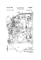
FIGURE 1 is a front elevational view of a tag marking machine incorporating the principles of this invention.
FIGURE 2 is a perspective view showing the side of themachine with the cover removed in order to show the driving mechanism.
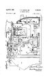
FIGURE 3 is a fragmentary plan view of the top of the machine with the printing head removed and illustrating the tag feed mechanism.
FIG. 4 is an enlarged, fragmentary side elevational view of the machine with the cover removed illustrating details a of the driving mechanism. In this view the various parts of the machine are shown in the home position.
FIGURE 5 is a view similar to FIGURE 4 in which the various parts of the machine have progressed from the home position in a tag feeding part of the cycle.
FIGURE 6 is a view similar to FIGURE 4 showing the parts in an advanced position in which the printing head is being inked.
FIGURE 7 is a view similar to FIGURE 4 showing the parts approaching a position in one cycle in which the ink pad of the machine is to be inked.
FIGURE 8 is a view similar to FIGURE 4 showing inking pad in a position in which it receives a new charge of ink. This figure illustrates the positions of the various parts of the machine just prior to their return to the condition of FIGURE 4 which is the home position and which designates the end of one cycle of operation.
FIGURE 9 is a fragmentary cross sectional view taken on the line 9-9 of FIGURE 3.
FIGURE 10 is a fragmentary cross-sectional view taken on the line 10-10 in FIGURE 4.
FIGURE 11 is a fragmentary cross-sectional view taken on the line 11I1 of FIGURE 10.
FIGURE 12 is a fragmentary cross-sectional View taken on the line 12-12 of FIGURE 11.
FIGURE 13 is a fragmentary cross-sectional view taken on the line 1313 of FIGURE 11.
FIGURE 14 is a fragmentary cross-sectional view taken on the line 1414 of FIGURE 11.
FIGURE 15 is a fragmentary cross-sectional view taken on the line 1515 of FIGURE 10.
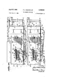
FIGURE 16 is a fragmentary view taken on a plane which passes through the machine just above the hopper, which is designed to receive the tags, and illustrating a gate mechanism.
FIGURE 17 is a view similar to FIGURE 16 illustrating the gate mechanism in a partially open condition.
FIGURE 18 is a view similar to FIGURES 16 and 17 showing the gate in a fully opened position.
FIGURE 19 is a fragmentary cross-sectional view looking at the underside of the ink pad carrier and its associated mechanism.
FIGURE 20 is a fragmentary elevational view illustrating the platen in the machine upon which the tags are printed.
FIGURE 21 is an enlarged cross-sectional view taken on the line Z1-2I of FIGURE 20 and illustrating the feed finger mechanism in its retracted position.
FIGURE 22 is a view similar to FIGURE 21 illustrating the feed finger mechanism in an advanced position.
FIGURE 23 is an enlarged cross-sectional view taken on the line 2323 of FIGURE 3 and illustrating the inking pad and its associated mechanism.
FIGURE 24 is a view similar to FIGURE 23 illustrating the inking pad and its associated mechanism in that FIGURE 25 is a view similar to FIGURE 23 in which the feed finger and its associated parts are in positions to apply a charge of ink to the type of the printing head.
FIGURE 26 is a fragmentary cross-sectional view taken on the line 2626 of FIGURE 4.
General reference is now made to FIGURE 1 which shows the front of a marking machine embodying the principles of this invention. The housing of the machine is designated generally by the numeral 1. Following conventional practices, this housing may consist of a number of removable sections in order to provide access to the interior of the machine. A printing head assembly is shown generally at 2,. The specific construction of the printing head forms no part of the present invention. Generally, however, as shown, the printing head comprises two sets of fifteen individual flexible bands each band of which is identified at 3. In each set, the bands are arranged side-by-side and each band has printing characters on it. These printing characters may be selectively brought into printing position by means of a combined band selector and band rotating device, indicated generally by the numeral 4 which is provided for each set. Each band is divided into a lower sector carrying the printing characters which are arranged in sequence along the band and a plurality of readable characters which are arranged in the same sequence as the printing characters along the upper sector of the band. Thus, by bringing a readable character into a reading position at the top of the printing head the operator is assured that a corresponding printing character is in printing position at the underside of the printing head.
A stack of multi-part tags, the upper one of which is identified at 5 in FIGURE 1, are placed in the machine so that as viewed in FIGURE 1, the heads of the tags are toward the left and the bottom of the tags are toward the right. The two sets of printing bands are designed to print two lines of characters which read from the top toward the bottom on each part of the tag. There is, in addition, a price line printing unit 6, which preferably also has printing bands in it simliar to those in the printing head assembly, which are arranged to print price marking indicia across the foot of each part of the multi-part tags. Thus, in the operation of the machine the tags move, one part at a time, out of the machine toward the observer as viewed in FIGURE 1.
The machine illustrated has an on-ofi, master switch 7 and an indicator light 8 which comes 'on when switch 7 is on. Controls are provided for the machine including a start switch 9, and a stop switch 10. Stop switch 10 comprises a manual stop. There are in addition, two automatic stops one of which is controlled by a counter 11 and the other of which, to be described later, becomes effective when the last tag of a stack is fed from the machine. Counter 11 is similar to that type disclosed in United States Patent No. 2,622,804 which may be preset to a selected number, corresponding to the number of tags to be run. The counter is arranged such that it counts backwards from a preselected number toward zero and when reaching zero, functions to decommission the machine. One cycle of the machine consists of the feeding and printing of one part of a multi-part tag. Thus, for counting, provision must be made to preset the machine for operation with tags of various widths or parts. For this purpose, a knob to control such mechanism is shown at the front of the machine at 12. Four positions for this knob are shown corresponding to single width, two part, three part, and four part tag operations, plus an ofi? position. This preset knob is used in conjunction with reset knob 13. The operation and interconnections of the counter, the control knob and the reset knob are disclosed in United States patent application Serial No. 346,240 filed February 20,1964. For the present purposes, however, it is sufiicient to state that the control knob 12 determines the complete tag count shown on the counter. Otherwise expressed, when the control knob 12 is set at one, which would be the setting for single width tags, the counter 11 makes one count for each cycle of the machine. In two part tag operation, the counter makes one count for each two cycles. In a three part tag operation the counter makes one count for each three cycles of the machine and so on, so that the counter does not tally cycles but tallies of the machine and it comprises two side walls 1616 and a wall 1'7 that is curved for'the sake of appearance and that constitutes both a back and a top wall. The forward portion'of wall 17, at the top of theframe member, is cut out as at 13 to accommodate a journal sleeve 19 that is an integral part of a hopper-platenassembly designated generally by the numeral Ztl. Journal sleeve 19 is pivotally mounted upon a shaft 21, the ends of which are appropriately journalled in the upper portion of the two side walls 16 of frame member 15. As shown in FIGURE 2, the forward part of the side walls are reinforced by added metal. In addition, following known practices, all frame members may have'ri'os in order to strengthen them in crucial areas and appropriate flanges are provided in order to bolt the frame members to base plate 14.
Another one of the. three outer frame members is shown at 22 in FIGURE 3. This is the largest oneof the frame members and it is well stressed, using known techniques, because it carries a bracket 23 which mounts the printing head 2 in cantilever fashion. The third outer frame member is shown at 24- and it is centered at the front of the machine. The fourth cast frame member is shown in FIGURE 2 at Ma and it provides a support for drive and control members as will be' explained. Following known techniques, the three outer frame members are joined by removable cover plates which protect the working parts of the machine and which add to the overall appearance of the machine.
The hopper-platen assembly 2'1 is pivotally mounted at the rear on shaft 21 for a rocking movement in which its front end has limited up and down swinging movement. Thus, in this machine, the printing head is stationary and tickets to be printed are carried by the assembly up into a position in which they are impressed by the type carried by the printing head.
More specifically, the hopper platen assembly comprises generally a table 25 at the. top over which labels and tags in strip form are adapted to be feditoward the printing head, a hopper designated generally 26, which is toward the front of the assembly and in which readyto-wear tickets are placed, and a platen 27 on which the to the journal sleeve 19 at the' rear as shown in dotted lines in FIGURES 4-8. The forward end of the boxlike casting 28 is closed by a wall 31, and the top is closed by a plate 32, which is appropriately bolted in place to the frame, this plate forming part of table 25. Bottom wall 29 and forward wall'31 are best illustrated in FIGURES 11 and 14. The two side walls 30-39 are best illustrated in FIGURES 14 and 16-18; As will be seen, the forward wall 31 is at the back of hopper 26. There is in addition an extension ,of the side wall of casting 28 at the right. This extension is designated 33 and may best be seen in FIGURES 9, 10, 13, 16 and 18, it is offset outwardly, as at 34, toward the right from side wall 30 in order to accommodatefhopper 26 and in addition it depends belowthe bottom wall 29 in order to provide support for mechanism at the forward end of the assembly, as will be explained.
A hollow box-like casting 35 is secured to the forward 6 to be printed slide as they are fed onto the platen. The left side of the hopper-platen assembly carries a plate 42 which is cut out as shown at 43 in FIGURE 2 to expose the hopper 26. The plate 42 extends forwardly under the platen and at the front of the hopper it is secured bymeans such as bolts to a seat 44 machined in the side of casting 35 as may be seen in FIGURES 16 and 17. In the rearward portion, plate 42 covers the casting 28 being removably secured to it for maintenance and adjustment pur-" poses by means of machine screws.
A shown in FIGURES 11 and 18, the forward wall 31 of casting 28 is coextensive with a back wall 45 of the hopper 26. Wall 45 is also coextensive with a wall 46 which forms the right side of the hopper, this wall being secured to the extension 33 in the area thereof to the rear of the box-like casting 35 that forms the forward end of the hopper-platen assembly. Additionally, the upper part of right wall 46 extends forwardly beyond the hopper area to provide the guide strip 41 to which reference has been made. The extension of the wall 46 is best seen in FIGURE 18. The front side of the hopper is defined by a vertical wall 47 which is fastened by means such as machine screws to the rear of the box-like casting 35. This is best shown in FIGURES 10 and 12. However, the wall 47 extends downwardly considerably below the casting 35 and its lower edge is substantially V-shaped. Wall 47 also has a vertical slot 4:; which extends substantially the full height of the wall, the purpose'of this slot to be explained later. The bottom wall of the hopper is formed by a plate 49 which is fastened to a flange 50 turned over at a right angle from the lower edge of wall 46 at one side thereofand fastened to a right angular flange 51 at the other side edge thereof. The latter right angular flange is secured to the plate 42 which extends along the left face of the hopper-platen assembly.
Tickets within the hopper are held against the forward wall 47 by means of a pusher plate 52 which is adjustable from the front to the rear of the hopper into any one of four positions so as to accommodate tickets having from one to four different parts. As maybe seen in FIGURE 11, the upper part of pusher plate 52 is turned over at a right angle to provide a rearward extension 53 that passes through a slot 54 at the upper edge of forward wall 31 of the box-like casting 28 to immediately underlie the'plate 32 that constitutes a table. I Although plate 32 is removed in FIGURE 18, it can be seen that the extension 53 c'onstitutes an extension of the table on which tags and labels in strip form may be fed toward the platen from the rear of the machine.
. A'spring urged latch member 55 iscarried at the top of the pusher plate 52 and its function is to hold the upper,- most one of a stack of tickets within the hopper from being pulled to the rear during the retracting movement of the feed fingers of the machine which are to be described later. projects through a rectangular opening 56 at thetop. of the pusher plate 52 and it is turned over toward the front of the machine to provide -a thin edge 57 which rests on top of the uppermost ticket within the hopper. A large headed rivet 58, which is fastened to the pusher plate 52 adjacent to its upper edge passes through a slot 59 in latch member'SS to hold it in place while permitting'a slight amount of vertical movement for this member; As shown in FIGURE 13, the lower end of latch member 55 straddles the upper end'of acast block 60 anda small coil spring 61 seated in a bore at the top of block 60 I normally urges the latch member 55 into the elevated 37 which is toward the right as viewed from the front may I .be secured by means such as'bolts to the extension 33 or .it may be cast as an integral part of it. The upper surface in this figure, casting 35 has a slot init to accommodate the forward end of a guide strip 41 against which tickets their movement, it being assumed that when strips are being fed notickets would be in the hopper to hold the latch member in the elevated position shown.
The upper end of the latch member 55'
Claims (1)
1. IN A MARKING MACHINE, THE IMPROVEMENT COMPRISING A PRINTING HEAD HAVING PRINTING CHARACTERS EXPOSED AT THE UNDERSIDE THEREOF, MEANS MOUTING SAID PRINTING HEAD ADJACENT TO THE FRONT OF THE MACHINE IN AN ELEVATED FIXED POSITION, A HOPPER-PLATEN ASSEMBLY HAVING THE REAT END THEREOF PIVOTED ON A HORIZONTAL AXIS FOR ROCKING MOTION IN WHICH A PLATEN ATOP THE FORWARD END THEREOF MOVES UP AND DOWN BENEATH SAID PRINTING CHARACTERS, A TICKET HOPPER ADAPTED TO HOLD A SUPPLY OF STACKED TICKETS IN SAID ASSEMBLY IMMEDIATELY TO THE REAR OF SAID PLATEN, MEANS INCLUDING SAID PLATEN DEFINING A GATGE THROUGH WHICH ONE TICKET AT A TIME MAY BE FED FROM SAID HOPPER ONTO SAID PLATEN, A FEED FINGER CARRIAGE MOUNTED FOR RECIPROCATING FORWARD AND BACKWARD MOVEMENT ON A SIDE OF SAID ASSEMBLY, FEED FINGERS MOUNTED ON SAID CARRIAGE AND ADAPTED TO ENGAGE THE UPPERMOST TICKET IN THE HOPPER AND FEED SAID TICKET ONTO SAID PLATEN DURING THE FORWARD MOTION OF SIAD FEED FINGER CARRIAGE, A DRIVE SHAFT EXTENDING FROM THE BACK
Priority Applications (1)
| Application Number | Priority Date | Filing Date | Title |
|---|---|---|---|
| US291019A US3180254A (en) | 1963-06-27 | 1963-06-27 | Tag marking machine |
Applications Claiming Priority (1)
| Application Number | Priority Date | Filing Date | Title |
|---|---|---|---|
| US291019A US3180254A (en) | 1963-06-27 | 1963-06-27 | Tag marking machine |
Publications (1)
| Publication Number | Publication Date |
|---|---|
| US3180254A true US3180254A (en) | 1965-04-27 |
Family
ID=23118489
Family Applications (1)
| Application Number | Title | Priority Date | Filing Date |
|---|---|---|---|
| US291019A Expired - Lifetime US3180254A (en) | 1963-06-27 | 1963-06-27 | Tag marking machine |
Country Status (1)
| Country | Link |
|---|---|
| US (1) | US3180254A (en) |
Cited By (4)
| Publication number | Priority date | Publication date | Assignee | Title |
|---|---|---|---|---|
| US3774530A (en) * | 1971-12-23 | 1973-11-27 | Am Totalisation Co Inc | Ticket issuing machine with cutter control |
| US3832943A (en) * | 1972-01-06 | 1974-09-03 | Monarch Marking Systems Inc | Printing apparatus |
| US3855457A (en) * | 1973-06-18 | 1974-12-17 | Ibm | Machine for processing merchandising tickets in both roll and individual form |
| US3902412A (en) * | 1972-01-06 | 1975-09-02 | Monarch Marking Systems Inc | Apparatus for printing and severing labels |
Citations (8)
| Publication number | Priority date | Publication date | Assignee | Title |
|---|---|---|---|---|
| US214797A (en) * | 1879-04-29 | Improvement in feed-boxes for printing-presses | ||
| US417994A (en) * | 1889-12-24 | And james brady | ||
| US1291074A (en) * | 1914-05-13 | 1919-01-14 | F B Redington Company | Blank-feeding device. |
| US1987395A (en) * | 1931-04-24 | 1935-01-08 | Accounting & Tabulating Corp | Machine for making records on statistical cards |
| US2333490A (en) * | 1941-03-01 | 1943-11-02 | Edward H Philippi | Advertising apparatus |
| US2627804A (en) * | 1948-09-30 | 1953-02-10 | Dennison Mfg Co | Machine for printing tickets, tags, cards, and the like |
| US2756674A (en) * | 1952-11-15 | 1956-07-31 | Monarch Marking Systems Inc | Inking system for automatic marking machines |
| US3089697A (en) * | 1961-09-14 | 1963-05-14 | Burroughs Corp | Stack conditioning apparatus |
-
1963
- 1963-06-27 US US291019A patent/US3180254A/en not_active Expired - Lifetime
Patent Citations (8)
| Publication number | Priority date | Publication date | Assignee | Title |
|---|---|---|---|---|
| US214797A (en) * | 1879-04-29 | Improvement in feed-boxes for printing-presses | ||
| US417994A (en) * | 1889-12-24 | And james brady | ||
| US1291074A (en) * | 1914-05-13 | 1919-01-14 | F B Redington Company | Blank-feeding device. |
| US1987395A (en) * | 1931-04-24 | 1935-01-08 | Accounting & Tabulating Corp | Machine for making records on statistical cards |
| US2333490A (en) * | 1941-03-01 | 1943-11-02 | Edward H Philippi | Advertising apparatus |
| US2627804A (en) * | 1948-09-30 | 1953-02-10 | Dennison Mfg Co | Machine for printing tickets, tags, cards, and the like |
| US2756674A (en) * | 1952-11-15 | 1956-07-31 | Monarch Marking Systems Inc | Inking system for automatic marking machines |
| US3089697A (en) * | 1961-09-14 | 1963-05-14 | Burroughs Corp | Stack conditioning apparatus |
Cited By (4)
| Publication number | Priority date | Publication date | Assignee | Title |
|---|---|---|---|---|
| US3774530A (en) * | 1971-12-23 | 1973-11-27 | Am Totalisation Co Inc | Ticket issuing machine with cutter control |
| US3832943A (en) * | 1972-01-06 | 1974-09-03 | Monarch Marking Systems Inc | Printing apparatus |
| US3902412A (en) * | 1972-01-06 | 1975-09-02 | Monarch Marking Systems Inc | Apparatus for printing and severing labels |
| US3855457A (en) * | 1973-06-18 | 1974-12-17 | Ibm | Machine for processing merchandising tickets in both roll and individual form |
Similar Documents
| Publication | Publication Date | Title |
|---|---|---|
| US2746679A (en) | Apparatus and systems for automatically recording, classifying, totalizing and auditing business transactions | |
| US2434512A (en) | Record controlled distributing and accounting machine | |
| US2134815A (en) | Printing | |
| US3651503A (en) | System for processing merchandizing tags having printed and magnetic information thereon | |
| GB674321A (en) | Improvements in or relating to selectively controlled recording apparatus | |
| US2271840A (en) | Price tag marking machine | |
| US2620726A (en) | Machine for imprinting and punching cards | |
| US3194154A (en) | Punch card controlled web feeding and printing apparatus | |
| US2132411A (en) | Printing machine | |
| GB2072102A (en) | Price-computing weighing scales with printer | |
| US3021988A (en) | Ticket printer | |
| US2991710A (en) | Tag making apparatus | |
| US2555732A (en) | Dual record feeding device | |
| US3095787A (en) | Laundry invoicing machine | |
| US2115760A (en) | Ticket issuing machine | |
| US2601283A (en) | Ticket issuing machine | |
| US2862708A (en) | Multiple form drive | |
| US2724328A (en) | boyden etal | |
| US2968236A (en) | Printing and punching machine | |
| US3194157A (en) | Method of printing workpieces | |
| US3213785A (en) | Machine for perforating tape and printing indicia thereon | |
| US3203627A (en) | Business control apparatus | |
| US2136941A (en) | Attaching and printing machine and method | |
| US2627804A (en) | Machine for printing tickets, tags, cards, and the like | |
| US2860575A (en) | sievers |