US3180121A - Clutch - Google Patents
Clutch Download PDFInfo
- Publication number
- US3180121A US3180121A US128721A US12872161A US3180121A US 3180121 A US3180121 A US 3180121A US 128721 A US128721 A US 128721A US 12872161 A US12872161 A US 12872161A US 3180121 A US3180121 A US 3180121A
- Authority
- US
- United States
- Prior art keywords
- cam
- latch
- stop means
- stop
- lug
- Prior art date
- Legal status (The legal status is an assumption and is not a legal conclusion. Google has not performed a legal analysis and makes no representation as to the accuracy of the status listed.)
- Expired - Lifetime
Links
- 230000000694 effects Effects 0.000 claims description 8
- 230000002093 peripheral effect Effects 0.000 claims description 6
- 238000006073 displacement reaction Methods 0.000 claims description 5
- 238000000926 separation method Methods 0.000 claims description 4
- 230000002441 reversible effect Effects 0.000 claims description 3
- 239000003990 capacitor Substances 0.000 description 10
- 238000002788 crimping Methods 0.000 description 3
- 238000003780 insertion Methods 0.000 description 3
- 230000037431 insertion Effects 0.000 description 3
- 230000013011 mating Effects 0.000 description 3
- 238000004080 punching Methods 0.000 description 3
- 238000004064 recycling Methods 0.000 description 2
- 101100233916 Saccharomyces cerevisiae (strain ATCC 204508 / S288c) KAR5 gene Proteins 0.000 description 1
- 208000027418 Wounds and injury Diseases 0.000 description 1
- 239000004020 conductor Substances 0.000 description 1
- 238000010276 construction Methods 0.000 description 1
- 125000004122 cyclic group Chemical group 0.000 description 1
- 230000001351 cycling effect Effects 0.000 description 1
- 230000006378 damage Effects 0.000 description 1
- 230000001934 delay Effects 0.000 description 1
- 230000000994 depressogenic effect Effects 0.000 description 1
- 238000010586 diagram Methods 0.000 description 1
- 208000014674 injury Diseases 0.000 description 1
- 238000004519 manufacturing process Methods 0.000 description 1
- 239000002184 metal Substances 0.000 description 1
- 238000012986 modification Methods 0.000 description 1
- 230000004048 modification Effects 0.000 description 1
- 230000003252 repetitive effect Effects 0.000 description 1
- 230000000717 retained effect Effects 0.000 description 1
- 239000011435 rock Substances 0.000 description 1
Images


Classifications
-
- F—MECHANICAL ENGINEERING; LIGHTING; HEATING; WEAPONS; BLASTING
- F16—ENGINEERING ELEMENTS AND UNITS; GENERAL MEASURES FOR PRODUCING AND MAINTAINING EFFECTIVE FUNCTIONING OF MACHINES OR INSTALLATIONS; THERMAL INSULATION IN GENERAL
- F16D—COUPLINGS FOR TRANSMITTING ROTATION; CLUTCHES; BRAKES
- F16D11/00—Clutches in which the members have interengaging parts
- F16D11/02—Clutches in which the members have interengaging parts disengaged by a contact of a part mounted on the clutch with a stationarily-mounted member
- F16D11/06—Clutches in which the members have interengaging parts disengaged by a contact of a part mounted on the clutch with a stationarily-mounted member with clutching members movable otherwise than only axially, e.g. rotatable keys
-
- B—PERFORMING OPERATIONS; TRANSPORTING
- B30—PRESSES
- B30B—PRESSES IN GENERAL
- B30B15/00—Details of, or accessories for, presses; Auxiliary measures in connection with pressing
- B30B15/12—Clutches specially adapted for presses
Definitions
- the present invention relates to a clutch for apparatus having a driven rotary member, and has particular application to a press which is adapted for punching electrical terminals from sheet metal strips and for crimping such terminals to electrical conductors, and similar operations which require precision work in a rapidly repetitive cycle.
- the mating punching, and/ or crimping dies are mounted with the lower die on the work table or other stationary part of the press and the cooperating upper die on the upper jaw of the press which is displaceable vertically relative to the table.
- the upper jaw is normally reciprocated by a single revolution clutch which causes it to be displaced downwardly to effect mating of the upper and lower dies and then return to the upper limit position for removal of the punched or crimped element and insertion of a fresh work piece.
- the removal of the completed work piece and the insertion of the fresh work piece is normally effected manually by the operator of the press and accordingly, it is desirable to insure completion of the single cycle of operation at the point where the upper jaw is at its greatest separation from the lower jaw.
- the present invention provides an improved clutch for apparatus such as a press which insures single-cycle operation of the press with the interruption precisely at the top of the stroke of the press, when the jaw is at its maximum spacing from the table.
- a further object of the present invention is to provide an electrically-controlled clutch for a press having an improved control circuit of simple form which enables rapid cycling of the press under the control of the operator without danger of recycling.
- the present invention provides a press which is of simple manufacture but which is fully effective in operation and use.
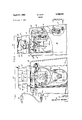
- FIG. 1 is a view in front elevation of a press made in accordance with the present invention.
- FIG. 2 is a view in side elevation of the press shown in FIG. 1;
- FIG. 3 is an enlarged sectional view taken on the line 33 of FIG. 2;
- FIG. 9 is a vertical sectional view taken on the line 9-9 of FIG. 6;
- FIG. 10 is a detached perspective view showing elements of the clutch shown in FIGS. 6 and 8;
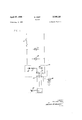
- FIG. 11 is a wiring diagram showing the control circuit for the press of the present invention.
- the press illustrated therein comprises a main support 20 having a work table 21 thereon which mounts a stationary die, in the present instance shown as a block 22.
- the table 21 serves as the stationary jaw of the press and includes bosses 23 for guiding supporting posts 24 of the upper jaw 25 which mounts an upper die, in the present instance shown as a block 26.
- the supporting posts 24 of the upper jaw 25 are mounted on a lower frame 27 below the table 21 which includes a cross piece 28.
- the frame 27 is reciprocated vertically by means of an eccentric 30 mounted on a drive shaft 31 and connected to the cross piece 28 by means of a toggle linkage 32 (see FIG. 3).
- V toggle linkage
- the toggle linkage 32 is readily adjustable to vary the position of the upper jaw 25 relative to the work table 21.
- the linkage 32 includes an upper link 33, a lower strap 34 engaged on the eccentric 30 and a toggle-adjusting arm 35 pivoted to the pivotal connection 36 between the upper link 33 and the strap 34.
- the arm 35 is anchored to the lower frame 27 by means of a bearing block 37 having an internal socket 38 for receiving a ball member 39 threadably engaged on a threaded shank 41 of the arm 35.
- the ball member 39 has formed integrally therewith a nut 40 for adjusting the ball on the threaded shank 41 of the arm 35 to thereby adjust the angle between the upper link 33 and the strap 34, and consequently, the distance between the eccentric 3t) and the connecting arm 28.
- a lock nut is provided at 42 to secure the ball 39 in adjusted position on the shank 41. 7
- FIG. 4 is an enlarged sectional view taken on line 44 of FIG. 3; 7
- FIG. 5 is a fragmentary sectional view similar to FIG. 3
- FIG. 6 is an enlarged sectional view taken on the line 66 of FIG. 2 with portions broken away to illustrate the operation of the single revolution clutch embodied in the appartus of the present invention
- FIG. 7 is a fragmentary view of elements of FIG. 6 showing the operation of the clutch
- FIG. 8 is a transverse sectional view taken on the line 83 of FIG. 6;
- rollers 54 are disposed between the cam faces 53 and the race ring 51 and are maintained in spaced relation by a cage 55.
- a coil spring 56 is secured at one end 57 to the cam 52 and at the other end 58 to the cage 55 to normally bias the cage clockwise relative to the cam whereby the rollers are urged into frictional engagement between the cam surfaces 53 and the inner surface of the race ring 51.
- the cage 55 is provided with a lug 62 operable to engage a stop surface 63 formed integrally with a latch lever 64 which is pivoted to the support 26 by a stud 65 and connected at 66 to the clevis 67 of a solenoid 68.
- the latch lever 64 is rocked clockwise to disengage the stop surface 63 from the lug 62 and permit the spring 56 to displace the cam rollers 54 into engagement between the cam surfaces 53 and the race ring 51 to thereby effect a driving connection between the pully 45 andthe shaft 31.
- the solenoid 68 is de-energized causing the lever 64 to rock to the position shown in FIG.
- the cam 52 is provided with a stop finger 70.
- the latch arm 64 is provided with a second stop surface 71 which normally is in the path of movement of the stop finger '70 to position the shaft 31 at the point where the upper jaw is in its upper limit position, It is noted that the stop surface 71 is trailing with respectto the stop surface 63 and is of greater radial extent than the latter surface.
- the stop surface 63 clears the lug 62 prior to clearance of the stop surface 71 from the arm 70. This delays the rotation ofthe cam 52 until the cage 55 is advanced, as shown in FIG. 7, so that the lug 62 is leading with respect to the finger 70.
- the leading stop surface 63 effects disengagement of the clutch, but the stop surface 71 permits the cam 52 to con tinue rotation to thereby insure frictional disengagement of the rollers 54 from between the cam surfaces 53 and the inner surface of the race ring 51.
- the impart of the lug 62 and the stop finger 70 against the latch lever 64 is cushioned by a plurality of cushioning members, in the present instance, O-rings 74 mounted between the stub shaft 65 and the latch lever 64.
- a supplementary latch is pivoted to the support as indicated at 76'and biased radially inward of the cam 52 by a spring '77.
- the latch lever 75 provides a third stop surface which operates to engage behind the stop finger with the stop surface 71, thereby effectively containing the stop finger 70 and insuring arrest of the shaft 31 at the point where the upper jaw 25 isat its upper limit position. It is noted that the stop finger arrests the movement of the upper jaw at the upper limit of its travel when its momentum is at a minimum.
- the clutch insures that the upper jaw .25 of the press is retained at its upper limit position at all times except during the cyclic operation of the press.
- the motor 47 of the press is energized continuously when the main switch 81 is closed.
- a pilot light is provided at 32 to indicate the energization .of the motor 47.
- a control box 83 is mounted on the machine through which the solenoid 68 is energized selectively under'the control of a foot treadle 84 which comswitch adapted to be plugged into the box as indicated at 85.
- the control box 83 includes a rectifier S6, in the presentinstance 500 ma, a resistance 57,in the present instance 50 ohms, a capacitor 88, in the present instance mfd., and a terminalboard 89.
- the switch of the foot treadle effects a connection placing the rectifier 86, the resistance 87, and the capacitor 88 in series across the line. This charges the capacitor 88 to the line voltage.
- the switch associated therewith disconnects the capacitor 88 from the'rectifier 86 and resistance 87 and connects the same across the solenoid 68 whereupon the capacitor discharges through the solenoid and momentarily energizes the same.
- the discharge of the capacitor is such as to provide sulficient power to displace the solenoid a necessary distance to release the latch arm 64 from the lug 62 and the arm 70.
- the capacitor cannot be recharged and the machine cannot be recycled.
- the capacitor 88 is again charged through the rectifier 86 and resistance 87; the value of theresistance is such as to permit almost instantaneous charging thereof. The circuitis therefore in condition for subsequent operation of the solenoid by again operating the foot treadle 84.
- the foot treadle When it is desired to interrupt operation of the machine, the foot treadle may be unplugged from the control box 83 and the machine is incapable of being operated. It has been found that upon disconnection of the foot treadle, the charge on the capacitor 88 bleeds 0E sufficiently rapidly to prevent operation of the solenoid 63 until the capacitor is again recharged to its full potential. In this manner, a simple, but highly effective, control circuit is provided which is fool-proof in operation, but is sufficiently rapid to enable sufiiciently rapid recycling of the machine under the control of the foot pedal to keep up with the manual dexterity of the fastest operator of the press.
- a clutch intermediate said driving motor and eccentric comprising an outer race ring connected to said driving motor, an inner cam having cam faces confronting the inner peripheral surface of said race ring, said cam being connected to said eccentric, rollers disposed between said cam faces and said inner peripheral surface, a cage for displacing said rollers on said cam faces between positions effecting driving connection and disconnection respectively of said race ring and cam, spring means biasing said cage in a direction to effect said driving connections, a lug on said cage, a latch member having a stop surface selectively engageable with said lug to overcome the bias of said spring means to displace said cage in the direction to efiect said disconnection, stop means on said cam, a second stop surface on said latch member engageable with the leading surface of said stop means to arrest rotation of said cam at a predetermined point in its cycle, means to displace said latch member between a released portion
- predetermined means biasing said second latch into the path of said'stop means, said second latch being displaced by said stop means upon passage of the latter past said second latch, and being free to engage behind said stop means upon passage of the latter beyond said second latch, and cushioning means mounting said first latch member for limited displacement relative to said second latch member to resiliently increase the separation between said latch members for reception of said stop means therebetween upon impart of said stop means against said first latch member.
- a solenoid for operating said latch member, and a treadle-operated control circuit for selectively energizing said solenoid.
- a double-throw switch operated by said treadle said control circuit including a capacitor connected to be charged through said foot treadle switch in its normal position and discharged through said solenoid and said foot treadle switch in its operating position.
- a clutch intermediate said drive means and said rotary member comprising an outer race ring connected to said drive means, an inner cam having cam faces confronting the inner peripheral surface of said race ring, said cam being connected to said rotary member, rollers disposed between said cam faces and said inner peripheral surface, a cage for displacing said rollers on said cam faces between positions effecting driving connection and disconnection respectively of said race ring and said cam, spring means biasing said cage in a direction to eifect said driving connections, a lug on said cage, a stop surface selectively engageable with said lug to overcome the bias of said spring means to displace said cage in the direction to effect said disconnection, stop means on said cam, a second stop surface engageable with the leading surface of said stop means to arrest rotation of said cam at a predetermined point in its cycle, and means to displace said stop surfaces between a released position out of the paths of said lug and stop means, and a locked position wherein said stop surfaces are
Landscapes
- Engineering & Computer Science (AREA)
- General Engineering & Computer Science (AREA)
- Mechanical Engineering (AREA)
- Press Drives And Press Lines (AREA)
Description
1 l 2 t w o h s w J t 3 w 4 an m m 6 w INVENTOR WALTER EL EY April 27, 1965 Filed Aug. 2, 19 61 ATTYS.
April 27, 1965 w, L I 3,180,121
CLUTCH Filed Aug. 2, 1961 4 Sheets-Sheet 2 FIG3. Z4
mvzm-on: WALTER ELEY MAW April 27, 1965 w. ELEY 3,180,121
CLUTCH Filed Aug. 2, 1961 4 Sheets-Sheet 3 FIG.6.
INVENTOR WALTER ELEY ATTYS.
W. ELEY April 27, 1965 CLUTCH 4 Sheets-Sheet 4 Filed Aug. 2, 1961 FIG. II.
.INVENTOR'. WALTER EL EY av WW ATTYS.
3,180,121 CLUTCH Walter Eley, Hatboro, Pa., assignor to Crockett Machine Products Company, Hathoro, Pa., a corporation of Pennsylvania Filed Aug. 2, 1961, Ser. No. 128,721 4 Claims. (Cl. 72-2) The present invention relates to a clutch for apparatus having a driven rotary member, and has particular application to a press which is adapted for punching electrical terminals from sheet metal strips and for crimping such terminals to electrical conductors, and similar operations which require precision work in a rapidly repetitive cycle.
In such presses, the mating punching, and/ or crimping dies are mounted with the lower die on the work table or other stationary part of the press and the cooperating upper die on the upper jaw of the press which is displaceable vertically relative to the table. The upper jaw is normally reciprocated by a single revolution clutch which causes it to be displaced downwardly to effect mating of the upper and lower dies and then return to the upper limit position for removal of the punched or crimped element and insertion of a fresh work piece. The removal of the completed work piece and the insertion of the fresh work piece is normally effected manually by the operator of the press and accordingly, it is desirable to insure completion of the single cycle of operation at the point where the upper jaw is at its greatest separation from the lower jaw. Furthermore, it is desirable to provide means for ready adjustment of the stroke to insure proper mating of the die when the jaw is in its lower limit position eifecting punching and/ or crimping engagement of the respective dies. Because of the manual removal and insertion of the work piece, it is imperative that the press cycle only once upon each actuation thereof so as to insure against injury to the operator.
With the foregoing in mind, the present invention provides an improved clutch for apparatus such as a press which insures single-cycle operation of the press with the interruption precisely at the top of the stroke of the press, when the jaw is at its maximum spacing from the table.
A further object of the present invention is to provide an electrically-controlled clutch for a press having an improved control circuit of simple form which enables rapid cycling of the press under the control of the operator without danger of recycling.
The present invention provides a press which is of simple manufacture but which is fully effective in operation and use.
All of the objects of the present invention are more fully set forth hereinafter with reference to the accompanying drawings, wherein:
FIG. 1,is a view in front elevation of a press made in accordance with the present invention;
FIG. 2 is a view in side elevation of the press shown in FIG. 1;
FIG. 3 is an enlarged sectional view taken on the line 33 of FIG. 2;
United States Patent FIG. 9 is a vertical sectional view taken on the line 9-9 of FIG. 6;
FIG. 10 is a detached perspective view showing elements of the clutch shown in FIGS. 6 and 8; and
FIG. 11 is a wiring diagram showing the control circuit for the press of the present invention.
Referring now to the drawings, the press illustrated therein comprises a main support 20 having a work table 21 thereon which mounts a stationary die, in the present instance shown as a block 22. The table 21 serves as the stationary jaw of the press and includes bosses 23 for guiding supporting posts 24 of the upper jaw 25 which mounts an upper die, in the present instance shown as a block 26. The supporting posts 24 of the upper jaw 25 are mounted on a lower frame 27 below the table 21 which includes a cross piece 28. The frame 27 is reciprocated vertically by means of an eccentric 30 mounted on a drive shaft 31 and connected to the cross piece 28 by means of a toggle linkage 32 (see FIG. 3). V
In the illustrated press, the toggle linkage 32 is readily adjustable to vary the position of the upper jaw 25 relative to the work table 21. To this end, the linkage 32 includes an upper link 33, a lower strap 34 engaged on the eccentric 30 and a toggle-adjusting arm 35 pivoted to the pivotal connection 36 between the upper link 33 and the strap 34. The arm 35 is anchored to the lower frame 27 by means of a bearing block 37 having an internal socket 38 for receiving a ball member 39 threadably engaged on a threaded shank 41 of the arm 35. The ball member 39 has formed integrally therewith a nut 40 for adjusting the ball on the threaded shank 41 of the arm 35 to thereby adjust the angle between the upper link 33 and the strap 34, and consequently, the distance between the eccentric 3t) and the connecting arm 28. A lock nut is provided at 42 to secure the ball 39 in adjusted position on the shank 41. 7 Thus, by adjusting the ball 39 on the shank 41, the
' clearance between the upper jaw 25 and the table 21 is readily adjusted to accommodate diiferent die members 22 and 26, as required, said adjustment also compensating for wear in the die members, if necessary.
The shaft 31 is driven from a drive pulley 45 through a single-revolution clutch 46 as described more fully hereinafter. The dlive pulley 45 is constantly driven from a suitable drive motor 47 by means of belts 48. The single-revolution clutch comprises an outer race ring 51 FIG. 4 is an enlarged sectional view taken on line 44 of FIG. 3; 7
FIG. 5 is a fragmentary sectional view similar to FIG. 3
, at a reduced scale showing the operation of the adjusting means of the present invention;
FIG. 6 is an enlarged sectional view taken on the line 66 of FIG. 2 with portions broken away to illustrate the operation of the single revolution clutch embodied in the appartus of the present invention;
FIG. 7 is a fragmentary view of elements of FIG. 6 showing the operation of the clutch;
FIG. 8 is a transverse sectional view taken on the line 83 of FIG. 6;
connected to the drive pully 45 and an inner cam mounted on the shaft 31 and having a series of circularly arranged cam faces 53 confronting the inner surface of the race ring 51. Rollers 54 are disposed between the cam faces 53 and the race ring 51 and are maintained in spaced relation by a cage 55. A coil spring 56 is secured at one end 57 to the cam 52 and at the other end 58 to the cage 55 to normally bias the cage clockwise relative to the cam whereby the rollers are urged into frictional engagement between the cam surfaces 53 and the inner surface of the race ring 51. The cage 55 is provided with a lug 62 operable to engage a stop surface 63 formed integrally with a latch lever 64 which is pivoted to the support 26 by a stud 65 and connected at 66 to the clevis 67 of a solenoid 68. Thus, upon energization of the solenoid 68, the latch lever 64 is rocked clockwise to disengage the stop surface 63 from the lug 62 and permit the spring 56 to displace the cam rollers 54 into engagement between the cam surfaces 53 and the race ring 51 to thereby effect a driving connection between the pully 45 andthe shaft 31. The solenoid 68 is de-energized causing the lever 64 to rock to the position shown in FIG. 6 under the action of the spring 68 to thereby engage the lug'62 upon the 78 upon engagement thereof prises a doublethrow a a upper jaw 26 is at its maximum spacing from the table 21. To this end, the cam 52 is provided with a stop finger 70. The latch arm 64 is provided with a second stop surface 71 which normally is in the path of movement of the stop finger '70 to position the shaft 31 at the point where the upper jaw is in its upper limit position, It is noted that the stop surface 71 is trailing with respectto the stop surface 63 and is of greater radial extent than the latter surface. Thus, when the latch lever 64 is rocked clockwise by energization of the solenoid 68, .the stop surface 63 clears the lug 62 prior to clearance of the stop surface 71 from the arm 70. This delays the rotation ofthe cam 52 until the cage 55 is advanced, as shown in FIG. 7, so that the lug 62 is leading with respect to the finger 70. After the latch arm 64 is returned to the position shown in FIG. 6, theleading stop surface 63 effects disengagement of the clutch, but the stop surface 71 permits the cam 52 to con tinue rotation to thereby insure frictional disengagement of the rollers 54 from between the cam surfaces 53 and the inner surface of the race ring 51. The impart of the lug 62 and the stop finger 70 against the latch lever 64 is cushioned by a plurality of cushioning members, in the present instance, O-rings 74 mounted between the stub shaft 65 and the latch lever 64.
To guard against counterclockwise rotation of the cam 52 upon impact of the finger with the surface 71, a supplementary latch is pivoted to the support as indicated at 76'and biased radially inward of the cam 52 by a spring '77. The latch lever 75 provides a third stop surface which operates to engage behind the stop finger with the stop surface 71, thereby effectively containing the stop finger 70 and insuring arrest of the shaft 31 at the point where the upper jaw 25 isat its upper limit position. It is noted that the stop finger arrests the movement of the upper jaw at the upper limit of its travel when its momentum is at a minimum. By this construction, the clutch insures that the upper jaw .25 of the press is retained at its upper limit position at all times except during the cyclic operation of the press.
In accordance with another feature of the invention, a simplified control reference to FIG. 11, the motor 47 of the press is energized continuously when the main switch 81 is closed. A pilot light is provided at 32 to indicate the energization .of the motor 47. A control box 83 is mounted on the machine through which the solenoid 68 is energized selectively under'the control of a foot treadle 84 which comswitch adapted to be plugged into the box as indicated at 85. The control box 83 includes a rectifier S6, in the presentinstance 500 ma, a resistance 57,in the present instance 50 ohms, a capacitor 88, in the present instance mfd., and a terminalboard 89. As
' shown inYFIG. 11, when the foot treadle is in its normal position, the switch of the foot treadle effects a connection placing the rectifier 86, the resistance 87, and the capacitor 88 in series across the line. This charges the capacitor 88 to the line voltage. When'the foot treadle is operated, the switch associated therewith, disconnects the capacitor 88 from the'rectifier 86 and resistance 87 and connects the same across the solenoid 68 whereupon the capacitor discharges through the solenoid and momentarily energizes the same. The discharge of the capacitor is such as to provide sulficient power to displace the solenoid a necessary distance to release the latch arm 64 from the lug 62 and the arm 70. As long as the foot treadle is depressed, the capacitorcannot be recharged and the machine cannot be recycled. When the foot treadle is released, the capacitor 88 is again charged through the rectifier 86 and resistance 87; the value of theresistance is such as to permit almost instantaneous charging thereof. The circuitis therefore in condition for subsequent operation of the solenoid by again operating the foot treadle 84.
circuit is provided to insure singleand instantaneous operation of the solenoid 68.: With point in its cycle,
When it is desired to interrupt operation of the machine, the foot treadle may be unplugged from the control box 83 and the machine is incapable of being operated. It has been found that upon disconnection of the foot treadle, the charge on the capacitor 88 bleeds 0E sufficiently rapidly to prevent operation of the solenoid 63 until the capacitor is again recharged to its full potential. In this manner, a simple, but highly effective, control circuit is provided which is fool-proof in operation, but is sufficiently rapid to enable sufiiciently rapid recycling of the machine under the control of the foot pedal to keep up with the manual dexterity of the fastest operator of the press.
While a particular embodiment of the present inven tion has been herein illustrated and described, it is not intended to limit the invention to such disclosure, but changes and modifications may be made therein and thereto within the scope of the following claims.
I claim:
1. In a press having an upper jaw mounted for vertical reciprocation relative to a work surface, an eccentric for displacing said jaw, and a driving motor for said eccentric, a clutch intermediate said driving motor and eccentric comprising an outer race ring connected to said driving motor, an inner cam having cam faces confronting the inner peripheral surface of said race ring, said cam being connected to said eccentric, rollers disposed between said cam faces and said inner peripheral surface, a cage for displacing said rollers on said cam faces between positions effecting driving connection and disconnection respectively of said race ring and cam, spring means biasing said cage in a direction to effect said driving connections, a lug on said cage, a latch member having a stop surface selectively engageable with said lug to overcome the bias of said spring means to displace said cage in the direction to efiect said disconnection, stop means on said cam, a second stop surface on said latch member engageable with the leading surface of said stop means to arrest rotation of said cam at a predetermined point in its cycle, means to displace said latch member between a released portion out of the paths of said lug and said stop means, and a locked position wherein said stop surfaces are in the paths of said lug and said stop means, a second latch mounted for displacement into and out of the path of said stop means and operable in the first-mentioned position to engage the trailing surface of said stop means to limit reverse rotation of said earn from said. predetermined means biasing said second latch into the path of said'stop means, said second latch being displaced by said stop means upon passage of the latter past said second latch, and being free to engage behind said stop means upon passage of the latter beyond said second latch, and cushioning means mounting said first latch member for limited displacement relative to said second latch member to resiliently increase the separation between said latch members for reception of said stop means therebetween upon impart of said stop means against said first latch member. a
2. In a press according to claim 1, a solenoid for operating said latch member, and a treadle-operated control circuit for selectively energizing said solenoid.
3. In a press according to claim 2, a double-throw switch operated by said treadle, said control circuit including a capacitor connected to be charged through said foot treadle switch in its normal position and discharged through said solenoid and said foot treadle switch in its operating position.
4. In apparatus having a driven rotary member, and drive means for said rotary member, a clutch intermediate said drive means and said rotary member comprising an outer race ring connected to said drive means, an inner cam having cam faces confronting the inner peripheral surface of said race ring, said cam being connected to said rotary member, rollers disposed between said cam faces and said inner peripheral surface, a cage for displacing said rollers on said cam faces between positions effecting driving connection and disconnection respectively of said race ring and said cam, spring means biasing said cage in a direction to eifect said driving connections, a lug on said cage, a stop surface selectively engageable with said lug to overcome the bias of said spring means to displace said cage in the direction to effect said disconnection, stop means on said cam, a second stop surface engageable with the leading surface of said stop means to arrest rotation of said cam at a predetermined point in its cycle, and means to displace said stop surfaces between a released position out of the paths of said lug and stop means, and a locked position wherein said stop surfaces are in the paths of said lug and said stop means, a third stop surface mounted for displacement into and out of the path of said stop means and operable in the first-mentioned position to engage the trailing surface of said stop means to limit reverse rotation of said cam from said predetermined point in its cycle, means biasing said third stop surface into the path said third stop surface to resiliently increase the separa tion between said second and third stop surfaces for reception of said stop means therebetween upon impact of said stop means against said second stop surface.
References Cited by the Examiner UNITED STATES PATENTS 1,710,705 4/29 Loshbough 83-524 1,775,79 1 9/3 0 Ungar 83-527 2,597,559 5/52 Bekey 83-524 2,644,560 7/53 Kleinschmidt 192-33 2,985,271 5/ 61 Wilson 192-33 CHARLES W. LANHAM, Primary Examiner.
UNITED STATES PATENT OFFICE CERTIFICATE OF CORRECTION April 27, 1965 Patent No a 3, 180 ,121
Walter Eley It is hereby certified that error appears in the above numbered patent requiring correction and that the said Letters Patent should read as correoteibelow.
(SEA-L.)
Attest:
ERNEST W. SWIDEB EDWARD J. BRENNER A1 testing I Officer Commissioner of Patents
Claims (1)
1. IN A PRESS HAVING AN UPPER JAW MOUNTED FOR VERTICAL RECIPROCATION RELATIVE TO A WORK SURFACE, AN ECCENTRIC FOR DISPLACING SAID JAW, AND A DRIVING MOTOR FOR SAID ECCENTRIE, A CLUTCH INTERMEDIATE SAID DRIVING MOTOR AND ECCENTRIC COMPRISING AN OUTER RACE RING CONNECTED TO SAID DRIVING MOTOR, AN INNER CAM HAVING CAM FACES CONFRONTING THE INNER PERIPHERAL SURFACE OF SAID RACE RING, SAID CAM BEING CONNECTED TO SAID ECCENTRIC, ROLLERS DISPOSED BETWEEN SAID CAM FACES AND SAID INNER PERIPHERAL SURFACE, A CAGE FOR DISPLACING SAID ROLLERS ON SAID CAM FACES BETWEEN POSITIONS EFFECTING DRIVING CONNECTION AND DISCONNECTION RESPECTIVELY OF SAID RACE RING AND CAM, SPRING MEANS BIASING SAID CAGE IN A DIRECTION TO EFFECT SAID DRIVING CONNECTIONS, A LUG ON SAID CAGE, A LATCH MEMBER HAVING A STOP SURFACE SELECTIVELY ENGAGEABLE WITH SAID LUG TO OVERCOME THE BIAS OF SAID SPRING MEANS TO DISPLACE SAID CAGE IN THE DIRECTION TO EFFECT SAID DISCONNECTION, STOP MEANS ON SAID CAM, A SECOND STOP SURFACE ON SAID LATCH MEMBER ENGAGEABLE WITH THE LEADING SURFACE OF SAID STOP MEANS TO ARREST ROTATION OF SAID CAM AT A PREDETERMINED POINT IN ITS CYCLE, MEANS TO DISPLACE SAID LATCH MEMBER BETWEEN A RELEASED PORTION OUT OF THE PATHS OF SAID LUG AND SAID STOP MEANS, AND A LOCKED POSITION WHEREIN SAID STOP SURFACES ARE IN THE PATHS OF SAID LUG AND SAID STOP MEANS, A SECOND LATCH MOUNTED FOR DISPLACEMENT INTO AND OUT OF THE PATH OF SAID STOP MEANS AND OPERABLE IN THE FIRST-MENTIONED POSITION TO ENGAGE THE TRAILING SURFACE OF SAID STOP MEANS TO LIMIT REVERSE ROTATION OF SAID CAM FROM SAID PREDETERMINED POINT IN ITS CYCLE, MEANS BIASING SAID SECOND LATCH INTO THE PATH OF SAID STOP MEANS, SAID SECOND LATCH BEING DISPLACED BY SAID STOP MEANS UPON PASSAGE OF THE LATTER PAST SAID SECOND LATCH, AND BEING FREE TO ENGAGE BEHIND SAID STOP MEANS UPON PASSAGE OF THE LATTER BEYOND SAID SECOND LATCH, AND CUSHIONING MEANS MOUNTING SAID FIRST LATCH MEMBER FOR LIMITED DISPLACEMENT RELATIVE TO SAID SECOND LATCH MEMBER TO RESILIENTLY INCREASE THE SEPARATION BETWEEN SAID LATCH MEMBERS FOR RECEPTION OF SAID STOP MEANS THEREBETWEEN UPON IMPART OF SAID STOP MEANS AGAINST SAID FIRST LATCH MEMBER.
Priority Applications (1)
| Application Number | Priority Date | Filing Date | Title |
|---|---|---|---|
| US128721A US3180121A (en) | 1961-08-02 | 1961-08-02 | Clutch |
Applications Claiming Priority (1)
| Application Number | Priority Date | Filing Date | Title |
|---|---|---|---|
| US128721A US3180121A (en) | 1961-08-02 | 1961-08-02 | Clutch |
Publications (1)
| Publication Number | Publication Date |
|---|---|
| US3180121A true US3180121A (en) | 1965-04-27 |
Family
ID=22436650
Family Applications (1)
| Application Number | Title | Priority Date | Filing Date |
|---|---|---|---|
| US128721A Expired - Lifetime US3180121A (en) | 1961-08-02 | 1961-08-02 | Clutch |
Country Status (1)
| Country | Link |
|---|---|
| US (1) | US3180121A (en) |
Cited By (1)
| Publication number | Priority date | Publication date | Assignee | Title |
|---|---|---|---|---|
| US5850685A (en) * | 1997-07-29 | 1998-12-22 | The Whitaker Corporation | Manual cycling mechanism for a magnetically powered terminating machine |
Citations (5)
| Publication number | Priority date | Publication date | Assignee | Title |
|---|---|---|---|---|
| US1710705A (en) * | 1927-12-19 | 1929-04-30 | James E Loshbough | Nonrepeat mechanism for power presses |
| US1775791A (en) * | 1927-05-20 | 1930-09-16 | Gustave A Ungar | Cutting shears and driving mechanism therefor |
| US2597559A (en) * | 1949-07-18 | 1952-05-20 | Bekey Andrew | Electromagnetically operated mechanism using resonance effects |
| US2644560A (en) * | 1947-08-20 | 1953-07-07 | Edward E Kleinschmidt | Latch operated clutch mechanism |
| US2985271A (en) * | 1957-12-27 | 1961-05-23 | Ibm | Clutch |
-
1961
- 1961-08-02 US US128721A patent/US3180121A/en not_active Expired - Lifetime
Patent Citations (5)
| Publication number | Priority date | Publication date | Assignee | Title |
|---|---|---|---|---|
| US1775791A (en) * | 1927-05-20 | 1930-09-16 | Gustave A Ungar | Cutting shears and driving mechanism therefor |
| US1710705A (en) * | 1927-12-19 | 1929-04-30 | James E Loshbough | Nonrepeat mechanism for power presses |
| US2644560A (en) * | 1947-08-20 | 1953-07-07 | Edward E Kleinschmidt | Latch operated clutch mechanism |
| US2597559A (en) * | 1949-07-18 | 1952-05-20 | Bekey Andrew | Electromagnetically operated mechanism using resonance effects |
| US2985271A (en) * | 1957-12-27 | 1961-05-23 | Ibm | Clutch |
Cited By (1)
| Publication number | Priority date | Publication date | Assignee | Title |
|---|---|---|---|---|
| US5850685A (en) * | 1997-07-29 | 1998-12-22 | The Whitaker Corporation | Manual cycling mechanism for a magnetically powered terminating machine |
Similar Documents
| Publication | Publication Date | Title |
|---|---|---|
| US2514261A (en) | Rotary intermittent feed mechanism | |
| US2383313A (en) | Protection apparatus | |
| US2291382A (en) | Indexing device | |
| GB1167372A (en) | Riveting Machines | |
| GB533358A (en) | Improvements relating to machines for assembling washers on screws or the like | |
| GB595398A (en) | Improvements in strip feeding means for presses | |
| GB678152A (en) | Improvements in or relating to fastener driving devices | |
| ES334435A1 (en) | Mechanism for ejecting workpieces from the matrices of upsetting machines | |
| US2492284A (en) | Trip mechanism for punch | |
| US2185769A (en) | Separable fastener attachment machine | |
| US2360545A (en) | Hide planimeter | |
| US2871727A (en) | Control drive apparatus | |
| US2663275A (en) | Draw press feeding device | |
| US2438842A (en) | Automatic dimpler | |
| GB830999A (en) | Improvements relating to embossing machines | |
| US1710705A (en) | Nonrepeat mechanism for power presses | |
| US1675426A (en) | Automatic stop mechanism | |
| US1962715A (en) | Vibrating riveter control | |
| GB1169293A (en) | Method and Apparatus for Crimping Electrical Connectors | |
| US3239039A (en) | Punch press with adjustable ram | |
| US2684615A (en) | Apparatus for pressing or blanking articles from strip material | |
| US3408883A (en) | Rotary indexing apparatus | |
| GB608338A (en) | Improvements relating to notching or punching presses | |
| GB839559A (en) | Improvements in or relating to machines adapted for use in assembling electrical components upon workpieces | |
| GB490012A (en) | Riveting or clinching machines |