US317536A - Railroad-rail - Google Patents
Railroad-rail Download PDFInfo
- Publication number
- US317536A US317536A US317536DA US317536A US 317536 A US317536 A US 317536A US 317536D A US317536D A US 317536DA US 317536 A US317536 A US 317536A
- Authority
- US
- United States
- Prior art keywords
- rail
- section
- sections
- base
- railroad
- Prior art date
- Legal status (The legal status is an assumption and is not a legal conclusion. Google has not performed a legal analysis and makes no representation as to the accuracy of the status listed.)
- Expired - Lifetime
Links
- 238000010276 construction Methods 0.000 description 3
- XEEYBQQBJWHFJM-UHFFFAOYSA-N Iron Chemical compound [Fe] XEEYBQQBJWHFJM-UHFFFAOYSA-N 0.000 description 2
- 239000000463 material Substances 0.000 description 2
- 229910000831 Steel Inorganic materials 0.000 description 1
- 229910052742 iron Inorganic materials 0.000 description 1
- 239000002184 metal Substances 0.000 description 1
- 229910052751 metal Inorganic materials 0.000 description 1
- 150000003839 salts Chemical class 0.000 description 1
- 239000010959 steel Substances 0.000 description 1
- 238000006467 substitution reaction Methods 0.000 description 1
Images
Classifications
-
- E—FIXED CONSTRUCTIONS
- E01—CONSTRUCTION OF ROADS, RAILWAYS, OR BRIDGES
- E01B—PERMANENT WAY; PERMANENT-WAY TOOLS; MACHINES FOR MAKING RAILWAYS OF ALL KINDS
- E01B5/00—Rails; Guard rails; Distance-keeping means for them
- E01B5/02—Rails
- E01B5/08—Composite rails; Compound rails with dismountable or non-dismountable parts
Definitions
- This invention relates to that class of twopart railroad-rails in which the separable base and head sections are provided with longitudinal projections, adapted to enter, respect ively, corresponding grooves in the other section.
- the object of my improvements is to provide a rail of this class which will possess advantages in point of simplicity and inexpensiveness of construction, and which will also possess superior merits of durability and general efficiency.
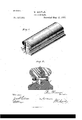
- Figure 1 is a perspective view of a section of my improved rail.
- Fig. 2 is a transverse sectional view of the same on a larger scale.
- the head-section may have any suitably-shaped tread, and is provided with a downwardlyextending longitudinal projection, a, at one side of which is provided a parallel longitudinal groove, (1 in the under side of the head.
- the base-section is formed with the usual flat bottom, and is provided with a projection, 72, extending longitudinally, and with a parallel longitudinal groove, b formed in its top surface at one side of the rib b.
- the sections are secured together by means of transverse bolts 0, extending through the ribs.
- the adjoining faces a b of the ribs are preferably straight and flat, and are perpendicularly arranged to secure a straight, even, and secure joint.
- the receiving-grooves correspond to the end edges of the tapering ribs, and their bottom surfaces, (L b are preferably inclined inwardly, as shown, which construction, in connection with the correspondingly-beveled edges of the ribs, (shown at a bi) meets the tendency of the ribs or sections to spread, and takes the consequent strain off the bolts.
- an enlargement, b extending longitudinally along the outer side of the said rib and serving to brace the same.
- the heads a of the securingbolts are preferably arranged at this side the web of the rail, thus enabling the bolts to be nutted or otherwise secured in the larger space at the opposite side of the web.
- the improved construction is very strong and durable, and also possesses the merits of simplicity and economy in material. It is also designed to break the joints, as the adjoining ends of two top sections may be disposed at about the center of a base-section and bolted in this position, thus forming a continuous rail. 8 5
- the base-section may be permanently secured in position upon the ties or sleepers, while the head-sections may be readily detached therefrom for purposes of substitution or repair. It is therefore designed to construct the sections of different metal.
- the base-section may be formed of iron to secure strength, and the head-section may be constructed of steel to best meet the wear.
Landscapes
- Engineering & Computer Science (AREA)
- Mechanical Engineering (AREA)
- Architecture (AREA)
- Civil Engineering (AREA)
- Structural Engineering (AREA)
- Train Traffic Observation, Control, And Security (AREA)
Description
W. HOOVER.
IL. Patented May 12,.1885.
N. PETERS, Fhoh-Lhhognphn Wnh'mgton. n.c
UNITED STATES PATENT OFFICE;
WILLIAM HOOVER, OF SALT RIVER, MICHIGAN.
RAI LROAD-RAlL.
SPECIFICATION forming part of Letters Patent No. 317,536, dated May 12, 1885.
Application filed August 25, 1884.
1' 0 aZZ whom, it may concern.-
Be it known that 1, WILLIAM Hoovnn, a citizen of the United States, residing at Salt River, in the county of Isabella and State of Michigan, have invented certain new and useful Improvements in Railroad-Rails; and I do hereby declare that the following is a full, clear, and exact description of the invention, which will enable others skilled in the art to which it appertains to make and use the same.
This invention relates to that class of twopart railroad-rails in which the separable base and head sections are provided with longitudinal projections, adapted to enter, respect ively, corresponding grooves in the other section.
The object of my improvements is to provide a rail of this class which will possess advantages in point of simplicity and inexpensiveness of construction, and which will also possess superior merits of durability and general efficiency.
In the drawings, Figure 1 is a perspective view of a section of my improved rail. Fig. 2 is a transverse sectional view of the same on a larger scale.
Corresponding parts in both figures are denoted by the same letters of reference.
Referring to the drawings, A and B desig nate, respectively, the head and base sections of my improved rail. The head-section may have any suitably-shaped tread, and is provided with a downwardlyextending longitudinal projection, a, at one side of which is provided a parallel longitudinal groove, (1 in the under side of the head. The base-section is formed with the usual flat bottom, and is provided with a projection, 72, extending longitudinally, and with a parallel longitudinal groove, b formed in its top surface at one side of the rib b. When the sections are adjusted together, the ends of the projections a and b respectively enter the grooves 11 and a and the projections thus form the usual web of the rail. The sections are secured together by means of transverse bolts 0, extending through the ribs. The adjoining faces a b of the ribs are preferably straight and flat, and are perpendicularly arranged to secure a straight, even, and secure joint. The outer faces, a I)",
(No model.)
of the ribs are beveled or inclined, so that the ribs taper toward their ends or edges and are broad and thick at their base, thus securing strength and economy in material, and obviating any necessity of making the receivinggrooves broad or large enough to weaken the sections of the rail. The receiving-grooves correspond to the end edges of the tapering ribs, and their bottom surfaces, (L b are preferably inclined inwardly, as shown, which construction, in connection with the correspondingly-beveled edges of the ribs, (shown at a bi) meets the tendency of the ribs or sections to spread, and takes the consequent strain off the bolts. Upon the flange or foot of the basesection, at the side of the rib b opposite from the groove, is formed an enlargement, b extending longitudinally along the outer side of the said rib and serving to brace the same. The heads a of the securingbolts are preferably arranged at this side the web of the rail, thus enabling the bolts to be nutted or otherwise secured in the larger space at the opposite side of the web.
The operation and advantages of my invention will be readilyunderstood by those skilled in the art to which it appertains.
The improved construction is very strong and durable, and also possesses the merits of simplicity and economy in material. It is also designed to break the joints, as the adjoining ends of two top sections may be disposed at about the center of a base-section and bolted in this position, thus forming a continuous rail. 8 5
The base-section may be permanently secured in position upon the ties or sleepers, while the head-sections may be readily detached therefrom for purposes of substitution or repair. It is therefore designed to construct the sections of different metal. For instance, the base-section may be formed of iron to secure strength, and the head-section may be constructed of steel to best meet the wear.
I claim as my invention and desire to secure by Letters Patent As an improvement in two-part railroadrails of the class described, the combination of the separable head-section provided with the longitudinal projection formed with a ICO straight perpendicular inner face and an inclined outer face spreading toward its base, and having its edge a beveled across, as described, and with the parallel groove having its bottom surface inclined inwardly across its width, and the base-section having a corresponding projection and groove and formed with the longitudinal enlargement b and the transverse securing-bolts having their heads seated upon said enlargement, substantially as r a and for the purpose set forth.
In testimony whereof I affix my signature in presence of two witnesses.
WILLIAM HOOVER.
Witnesses:
M. G. SHAPPEE, L. (3. GRIFFITH.
Publications (1)
| Publication Number | Publication Date |
|---|---|
| US317536A true US317536A (en) | 1885-05-12 |
Family
ID=2386681
Family Applications (1)
| Application Number | Title | Priority Date | Filing Date |
|---|---|---|---|
| US317536D Expired - Lifetime US317536A (en) | Railroad-rail |
Country Status (1)
| Country | Link |
|---|---|
| US (1) | US317536A (en) |
-
0
- US US317536D patent/US317536A/en not_active Expired - Lifetime
Similar Documents
| Publication | Publication Date | Title |
|---|---|---|
| US317536A (en) | Railroad-rail | |
| US774401A (en) | Rail. | |
| US811130A (en) | Rail-joint. | |
| US779491A (en) | Rail-joint. | |
| US708908A (en) | Railway-track joint. | |
| US438444A (en) | Railway-rail | |
| US795733A (en) | Rail-joint. | |
| US609024A (en) | Railroad-rail | |
| US1090504A (en) | Rail-joint. | |
| US312490A (en) | Railway-rail joint | |
| US1036219A (en) | Rail-joint. | |
| US919681A (en) | Railroad-rail joint. | |
| US241908A (en) | bedell | |
| US1130921A (en) | Rail-joint. | |
| US713083A (en) | Railway-rail joint. | |
| US1005414A (en) | Rail-joint. | |
| US348484A (en) | Clark wilcox | |
| US898799A (en) | Rail-joint. | |
| US1070401A (en) | Rail-joint. | |
| US1010923A (en) | Rail-joint. | |
| US808151A (en) | Railway-rail. | |
| US718354A (en) | Rail-joint. | |
| US750859A (en) | Railway-rail joint | |
| US663894A (en) | Rail-joint. | |
| US343124A (en) | Rail-joint |