US3174635A - Backhoe - Google Patents
Backhoe Download PDFInfo
- Publication number
- US3174635A US3174635A US226901A US22690162A US3174635A US 3174635 A US3174635 A US 3174635A US 226901 A US226901 A US 226901A US 22690162 A US22690162 A US 22690162A US 3174635 A US3174635 A US 3174635A
- Authority
- US
- United States
- Prior art keywords
- vane
- fluid
- boom
- backhoe
- shaft
- Prior art date
- Legal status (The legal status is an assumption and is not a legal conclusion. Google has not performed a legal analysis and makes no representation as to the accuracy of the status listed.)
- Expired - Lifetime
Links
- 239000012530 fluid Substances 0.000 claims description 46
- 238000013459 approach Methods 0.000 description 4
- 230000000694 effects Effects 0.000 description 4
- 238000012856 packing Methods 0.000 description 3
- 230000008878 coupling Effects 0.000 description 2
- 238000010168 coupling process Methods 0.000 description 2
- 238000005859 coupling reaction Methods 0.000 description 2
- 230000002093 peripheral effect Effects 0.000 description 2
- 230000002441 reversible effect Effects 0.000 description 2
- 240000008042 Zea mays Species 0.000 description 1
- 235000005824 Zea mays ssp. parviglumis Nutrition 0.000 description 1
- 235000002017 Zea mays subsp mays Nutrition 0.000 description 1
- 230000008602 contraction Effects 0.000 description 1
- 235000005822 corn Nutrition 0.000 description 1
- 230000003247 decreasing effect Effects 0.000 description 1
- 238000007599 discharging Methods 0.000 description 1
- 238000000034 method Methods 0.000 description 1
- 230000000284 resting effect Effects 0.000 description 1
Images

Classifications
-
- E—FIXED CONSTRUCTIONS
- E02—HYDRAULIC ENGINEERING; FOUNDATIONS; SOIL SHIFTING
- E02F—DREDGING; SOIL-SHIFTING
- E02F3/00—Dredgers; Soil-shifting machines
- E02F3/04—Dredgers; Soil-shifting machines mechanically-driven
- E02F3/28—Dredgers; Soil-shifting machines mechanically-driven with digging tools mounted on a dipper- or bucket-arm, i.e. there is either one arm or a pair of arms, e.g. dippers, buckets
- E02F3/36—Component parts
- E02F3/38—Cantilever beams, i.e. booms;, e.g. manufacturing processes, forms, geometry or materials used for booms; Dipper-arms, e.g. manufacturing processes, forms, geometry or materials used for dipper-arms; Bucket-arms
- E02F3/382—Connections to the frame; Supports for booms or arms
- E02F3/386—Connections to the frame; Supports for booms or arms the boom being laterally shiftable relative to the frame
Definitions
- This invention relates to a supporting means between an earth working implement and a main support or frame for the implement. More particularly this invention relates to the combination swing cylinder and supporting structure used for mounting and swinging a backhoe. Still more particularly, this invention relates to a braking mechanism used in the swing cylinder which slows or brakes the swing of the backhoe as it approaches its maximum limit of swing.
- This invention generally relates to an improvement of the swing cylinder and backhoe shown and described in U.S. Patent 2,994,446 which issued to A. J. Van Auwelaer and O. R. Johannson August 1, 1961.
- a tractor having a transverse supporting stand on its rear end which carries transversely extending tracks or guides.
- a swing structure including a rotary vane type cylinder composed of an upright shaft and an upright barrel surrounding the shaft and defining with the shaft the hydraulic cylinder
- Supported on the barrel through suitable brackets is a boom that carries the backhoe structure and an hydraulic cylinder utilized to raise and lower the boom.
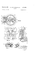
- FIG. 1 is a rear perspective view of a backhoe and tractor, the backhoe incorporating the structure of the present invention.
- FIG. 2 is a side and rear perspective view of the supporting swivel structure between the boom of the backhoe and its supporting stand.
- FIG. 3 is a vertical sectional view of the swivel structure between the boom of the backhoe and its supporting stand.
- FIG. 4 is a sectional view taken substantially along the lines 4-4 of FIG. 3.
- FIG. 5 is a rear view of the main portion of the swing cylinder.
- FIG. 6 is a sectional view taken substantially along the line 66 of FIG. 5.
- FIG. 7 is an enlarged sectional view taken substantially along the line 77 of FIG. 5.
- FIG. 8 is a sectional view taken along the line 88 of FIG. 7.
- the earth working implement or backhoe :10 is of the type normally mounted on the rear of the tractor 11 or other type of mobile vehicle.
- the tractor 11 includes a main power unit or engine, not shown, a body 12. supported on front wheels, also not shown, and a pair of rear traction wheels 13, 14.
- An operators station, indicated by its location by the steering wheel 15, is provided on the tractor and includes therein a seat which is reversible and which may be moved into position to either drive the tractor or to operate the controls, as indicated by the levers 16, for operating the backhoe 10.
- the backhoe 19 includes a vertically adjustable boom 20 basically supported at its lower end by a supporting stand or main frame, indicated in its entirety by the reference numeral 21.
- the boom 20 is controlled in its vertical movement by an extensible hydraulic unit or cylinder 24.
- the backhoe it) also includes a dipper stick 25 pivoted at 26 to the outer end of the boom 29.
- the dipper stick is swung vertically about the pivot '26 by means of a hydraulic cylinder 27.
- Pivotally supported at 30 on the outer end of the dipper stick 25 is a bucket 81 controlled by a hydraulic cylinder 32.
- Other types of buckets and earth cutting or moving implements could, of course, be used on the backhoe dipper stick.
- the hydraulic cylinder 32 is connected to the bucket by means of a roll-over linkage 33. Up to this point description of the backhoe is limited and only generally described, all features and characteristics of such being more or less conventional and well known within the art.
- the stand or frame 21 is of the type shown and described in detail in a pending application of John L. French, Albert J. Van Auwelaer, and Douglas C. Ager, Ser. No. 760,266, filed September 10, 1958.
- the stand 21 includes therein an upright structure supported on transversely spaced legs 35, 36 engaging the ground and supporting the stand 21.
- Upper and lower tracks means 37, 38 respectively face rearwardly from the stand structure 21 and have transversely spaced openings 39 across the tracks 37, B8.
- a rigid supporting structure 4t? is mounted on the tracks 37, 33 of the main stand 21 and includes upper and lower guides 41, 42 which hook behind the respective tracks 37, 38 so as to support the structure 40 in cantilever fashion on the tracks.
- Pads 43, 44 project forwardly from the rear of the structure 40 and ride against the face of the tracks 37, 38.
- a forwardly projecting portion 45 overlies the lower track 38.
- the structure further includes a pair of rearwardly projecting upper and lower support portions 46, 47, each of which have large openings 48, 49. Also provided to further support the structure 410 on the tracks 37, 38 are bolts, such as at 50, 51, on opposite sides of the structure 40 which are received in the openings 39 of the tracks 37, 38. The bolts obviously hold the structure 40 in the desired position on the tracks.
- Cap members 55, 56 are positioned in the openings 48, 49 respectively and are detachably connected to the upper and lower support portions 46, 47 by means of bolts 57, 58 respectively.
- the caps 55, 56 carry thrust bearings 5-9, 60 respectively which carry upper and lower end portions 61, '62 of an upright barrel or casing structure 63.
- the barrel structure 63 further includes an upright cylinder wall 64 with an inner periphery spaced radially from the axis formed by the bearings 59, 60 and the end Walls or portions 61, 62 rigidly fixed to the cylinder portion 64 by means of bolts 65, 66 respectively,
- the upper and lower portions '61, 62 are provided with rearwardly projecting brackets 70, 71.
- the rearwardly projecting brackets or portions 70, 71 are provided with transverse pivot pins 72, 73 respectively .pivo-tally connecting the hydraulic cylinder 24 and the forward end of the boom 20 to the casing 63.
- the rearwardly projecting bracket is further provided with transverse opening means 74 which receives a pin 75.
- the boom 20 is provided with a bracket 76 having an opening therein which will register with the opening 74 to receive the pin 75.
- the bracket 76 and the pin therefore operate as means locking the boom 20 in its vertical uppermost position and serves generally for the purpose of relieving the pressure within the cylinder 24 when the backhoe is in transport position or otherwise not in use.
- An upright columnar member 'or shaft structure 80 is carried by the lower support means or cap56 and is'held rigidly against rotation by a splined end 81 splined to the internal surface of the cap 56.
- the shaft structure 80 is supported at its upper and lower end portions in the upper and lower portions 61, 62 of the casing 63, packing means, as at 82, 83, being provided to seal the journals between the portions 61, 62 and the shaft 80 against leakage of fluid.
- a first vane means is fixed to the shaft 80 and includes therein a T-shaped vane 85 with the cross bar of the T having an arcuate-shaped section resting against the shaft 80.
- the vane 85 is fixed to the shaft 80 by means of bolts '87 received in suitably tapped openings 88 in the shaft .80.
- Suitable dowel pins 89 extend between the vane 85 and shaft 80 to add strength to the connection of the vane to the shaft.
- Suitable openings 90 are provided in the shaft 80 to receive the dowel pins 89.
- the vane 85 extends the entire height of the fluid chamber within the casing '63 and has its outer peripheral edges engaging the internal surfaces of the end portions 61, 62 and the inner periphery of the cylindrical portion '64.
- suitable groove extends around the periphery of the vane 85 and seats a packing ring 91 to seal the edges of the vane 85 against the respective adjacent surfaces.
- A'second vane member 95 is fixed to the cylindrical portion 64 of the casing by means of bolts 96-.
- the vane 95 is also T-shaped having the cross bar of the T arcuate-shaped to fit adjacent and snugly against the inner periphery of the cylindrical portion 64.
- the vane 95 extends the height of the chamber formed internally of the casing 63 and has its inner terminal edge adjacent to the columnar member 'or shaft 80.
- a peripheral groove is provided around the vane 95 to receive packing 98 which fits against the internal surfaces of the end portions 61, 62, the internal surface of the cylindrical portion 64, and the outer surface of the columnar member 80.
- the vanes 85, 95 divide the fluid chamber formed within the casing 63 into compartments on opposite sides of the vanes.
- a of L-shaped fluid pressure inlets or passage Ways 100, 101 are provided in the vane member 95 and opens respectively into each of the aforementioned corn partrnents through lower horizontal portions of the pass sageways.
- the couplings 102, 103 are connected to hydraulic hoses 104, respectively. Fluid is fed through the hoses 104-, 105 by conventional type valve means con trolled by the lever 16 on the main frame 21 of the back hoe.
- the basic fluid source comes from "the tractor 11 also in conventional manner.
- Fluid outlet passages-1'06, 107 are provided in the" base wall 62 of the barrel chamber 63 and have two rows of apertures 108, 109 respectively opening upwardlyinto the chamber on opposite sides of the fixed vane '85; As may be seen from viewing FIG. 4, as the movable vane 95 and barrel structure 63 moves angularly or advances toward the fixed vane 85, one of the rows of apertures 108, 109 will progressively pass under the fixed vane '85. As this occurs the discharge capacity of that compart ment will be reduced and the rate of swinging of the barrel structure 63 and the backhoe will progressively slow down until the entire row of discharge apertures have passed under the vane and the entire backhoe as well as the barrel 63 is locked against movement.
- the location of the discharge outlets or aper tures 103, 109 provide for a gradual slowing down or braking of the backhoe in its lateral swinging motion.
- the apertures 108 109 are in rows extending from a position closely ad jjacent the sides of the vane 95 to a position well in the chamber. It is rather obvious that the discharge apertures 108, 109 could be variously placed to obtain some what of the same result as their present location.
- the passages 106, 107 are connected to the fittings 102, 103 by means of tubes 110, 111, fittings 112, 113 being provided to connect the tubes 110, 111 to there 'spective passages 106, v107.
- the tubes 1 10, 1'11 lead into elbow fittings 1'14, 115 which in turn are connected to and open into fittings 102, 103 respectively.
- Each of the fittings 102, 103 are identical and each is provided with central passage 117, which feeds ma terial directly to the afore-mentioned L-shaped passages 100, 1 01. Orifices, such as at 116, feed from the hoses 104, 105 to the passage 117.
- the end of the passage 117 is enlarged as at 118 to provide a shoulder 119
- a poppet valve 120 is disposed in the end 118.
- the poppet; valve 120 is square in cross section and is relieved at one end such as at 121 to permit flow of fluid from the hose 104 or 105 into their respective L-shaped openings 100, 101.
- a supporting means for an earth working implement between a main frame and a boom comprising: concentric upright barrel and shaft structures journaled relative to one another to permit rotation therebetween, said barrel structure having walls enclosing at least a portion of the shaft structure and defining therewith a fluid chamber; means mounting the boom on one of the structures; means mounting the other structure on the frame against movement; a first vane fixed to the latter structure; a second vane on the former structure and movable relative to the first vane; fluid inlet and outlet means on opposite sides of the fixed vane for swinging the second vane and boom laterally; and a throttling system associated with the outlet means responsive to advancement of the second vane toward the first vane to reduce the rate of discharge of the fluid in advance of the second vane.
- a supporting means for an earth working implement between a main frame and a boom comprising: concentric upright barrel and shaft structures journaled relative to one another to permit rotation therebetween, said barrel structure having walls enclosing at least a portion of the shaft structure and defining therewith a fluid chamber; means mounting the boom on one of the structures; means mounting the other structure on the frame against movement; a first vane fixed to the latter structure; a second vane on the former structure and movable relative to the first vane; a fluid pressure inlet on opposite sides of the fixed vane for effecting advancement of the second vane toward the first; fluid discharge outlets opening into the chamber and angularly related relative to the axis of concentricity whereby advancement of the second vane toward the first vane will reduce the rate of discharge of the fluid in advance of the second vane; and fluid conduit means associated with the pressure inlets and outlets for effecting the direction of movement of the second vane.
- a supporting means for an earth working implement between a main frame and a boom comprising: concentric upright barrel and shaft structures journaled relative to one another to permit rotation therebetween, said barrel structure having walls enclosing at least a portion of the shaft structure and defining therewith a fluid chamber; means mounting the boom on one of the structures; means mounting the other structure on the frame against movement; a first vane fixed to the latter structure; a second vane on the former structure and movable relative to the first vane; fluid pressure inlets on opposite sides of the fixed vane for swinging the second vane and boom laterally; fluid outlets on opposite sides of the fixed vane angularly spaced in the chamber whereby advancement of the second vane toward the first vane will reduce the rate of discharge of the fluid in advance of the second vane; and fluid conduit means associated with the inlets and outlets to effect advancement of the second vane toward the first vane and adjustable to effect advancement in opposite directions.
- a supporting means for an earth working implement between a main frame and a boom comprising: concentric upright barrel and shaft structures journaled relative to one another to permit rotation therebetween, said barrel structure having walls enclosing at least a portion of the shaft structure and defining therewith an annular fluid chamber; means mounting the boom on one of the structures; means mounting the other structure on the frame against movement; a first vane fixed to the latter structure; a second vane on the former structure and movable relative to the first vane; a fluid pressure inlet adjacent one side of the fixed vane for advancing the second vane toward the opposite side of the fixed vane; a series of fluid outlets opening into the chamber beginning adjacent the opposite side of the fixed vane and extending angularly around the chamber whereby advancement of the second vane toward said opposite side will reduce the rate of discharge of the fluid in advance of the second vane.
- a supporting means for an earth working implement between a main frame and a boom carrying an earth working tool comprising: concentric upright barrel and shaft structures journaled relative to one another to permit rotation therebetween, said barrel structure having walls enclosing at least a portion of the shaft structure and defining therewith an annular fluid chamber, means mounting the boom on one of the structures; means mounting the other structure on the frame against movement; a first vane fixed to the latter structure; a second vane on the former structure and movable angularly around the chamber and dividing the chamber into first and second expandable and contractable compartments; fluid inlet and outlet means opening into the respective compartments, said latter means being adjustable to effect flow of fluid into and out of the respective compartments; a throttling system associated with the inlet and outlet means responsive to contraction of either of the respective compartments to reduce the rate of flow of the fluid effecting the advance of the second vane.
- a supporting means for an earth working implement between a main frame and a boom carrying an earth working tool comprising: concentric upright barrel and shaft structures journaled relative to one another to permit rotation therebetween, said barrel structure having walls enclosing at least a portion of the shaft structure and defining therewith an annular fluid chamber; means mounting the boom on one of the structures; means mounting the other structure on the frame against movement; a first vane fixed to the latter structure; a second vane on the former structure and movable angularly around the chamber to opposite limits of movement adjacent opposite sides of the fixed vane, said second vane dividing the chamber into first and second expandable and contractable compartments; fluid inlet and outlet means opening into the respective compartments, said latter means being adjustable to effect flow of fluid into and out of the respective compartments; a throttling system associated with the outlet means responsive to advancement of the second vane toward one of its limits of movement to reduce the rate of flow of fluid effecting the advance of the second vane.
- a supporting means for an earth working implement between a main frame and a boom carrying an earth Working tool comprising: concentric upright barrel and shaft structures journaled relative to one another to permit rotation therebetween, said barrel structure having walls enclosing at least a portion of the shaft structure and defining therewith an annular fluid chamber; means mounting the boom on one of the structures; means mounting the other structure on the frame against movement; a first vane fixed to the latter structure; a second vane on the former structure and movable angularly around the chamber to opposite limits of movement adjacent opposite sides of the fixed vane, said second vane dividing the chamber into first and second expandable and contractable compartments; fluid inlet and outlet means opening into the respective compartments, said latter means being adjustable to eifect flow of fluid into and out of the respective compartments; fluid discharge apertures associated with the outlet means disposed in the chamber to partially pass behind the second vane as it advances toward its limit of movement to thereby reduce the rate of flow of fluid efiecting the advance of the second vane.
Landscapes
- Engineering & Computer Science (AREA)
- Mechanical Engineering (AREA)
- Mining & Mineral Resources (AREA)
- Civil Engineering (AREA)
- General Engineering & Computer Science (AREA)
- Structural Engineering (AREA)
- Operation Control Of Excavators (AREA)
- Soil Working Implements (AREA)
- Catching Or Destruction (AREA)
- Fluid-Damping Devices (AREA)
Description
March 1955 A. J. VAN AUWELAER ETAL 3,174,535
BACKHOE 2 Sheets-Sheet 1 Filed Sept. 28, 1962 IN VENTORS ALBERT d. VAN AUWELAER JOHN AANDERSON ATTORNEY March 23, 1965 A, J. VAN AUWELAER ETA]. 3,174,635
BACKHOE Filed Sept. 28, 1962 2 Sheets-Sheet 2 8 INVENTORS ALBERTJ.VAN AU LAER BY JOHN A.AND ON Gull,
ATTORNEY United States Patent Cfiice air ines Patented Mar. as, 1965 3,174,635 BACKHOE Albert J. Van Auwelaer and John A. Anderson, Moline,
111., assignors to Deere & Company, Moline, 111., a corporation of Delaware Filed Sept. 28, 1962, Ser. No. 226,901 8 Claims. (Cl. 214-438) This invention relates to a supporting means between an earth working implement and a main support or frame for the implement. More particularly this invention relates to the combination swing cylinder and supporting structure used for mounting and swinging a backhoe. Still more particularly, this invention relates to a braking mechanism used in the swing cylinder which slows or brakes the swing of the backhoe as it approaches its maximum limit of swing.
This invention generally relates to an improvement of the swing cylinder and backhoe shown and described in U.S. Patent 2,994,446 which issued to A. J. Van Auwelaer and O. R. Johannson August 1, 1961. In the structure shown and described in that patent, there is provided a tractor having a transverse supporting stand on its rear end which carries transversely extending tracks or guides. Supported on the tracks or guides is a swing structure including a rotary vane type cylinder composed of an upright shaft and an upright barrel surrounding the shaft and defining with the shaft the hydraulic cylinder Supported on the barrel through suitable brackets is a boom that carries the backhoe structure and an hydraulic cylinder utilized to raise and lower the boom.
In the above type backhoe mounting arrangement, difficulty occurs in stopping the swing of the backhoe particularly at the extreme ends of the arc of swing of the backhoe. This occurs due to the fact that there is nothing to slow down or stop the backhoe except to lock the iiuid of the swing cylinder This, however, creates an abrupt stop in the backhoe. It should be remembered that a backhoe, particularly when loaded, is relatively heavy and once a velocity or speed of swing is created, it is diiiicult to slow down due to the inertia of the backhoe and its load. Often times damage may be done to the frame and particularly to the pivot pins connecting the various portions or parts of the backhoe.
With the above in mind, it is the primary object of the present invention to incorporate in the swing cylinder an hydraulic braking arrangement which utilizes the abovedescribed portions of the backhoe and which operates to slow down the movement or swing of the backhoe as it approaches its limits of swing.
Specifically it is an object of the present invention to provide a series of discharge apertures in the rotary type swing cylinder which will progressively become closed as the movable vane approaches its limits. Consequently the discharge capacity of the hydraulic cylinder will progressively become smaller and the decreased rate of discharge will operate as a brake in slowing down the swing of the backhoe.
Other objects and advantages of the invention will become apparent to those skilled in the art as the nature of the invention is better understood from the following description and as shown in the accompanying drawings:
FIG. 1 is a rear perspective view of a backhoe and tractor, the backhoe incorporating the structure of the present invention.
FIG. 2 is a side and rear perspective view of the supporting swivel structure between the boom of the backhoe and its supporting stand.
FIG. 3 is a vertical sectional view of the swivel structure between the boom of the backhoe and its supporting stand.
FIG. 4 is a sectional view taken substantially along the lines 4-4 of FIG. 3.
FIG. 5 is a rear view of the main portion of the swing cylinder.
FIG. 6 is a sectional view taken substantially along the line 66 of FIG. 5.
FIG. 7 is an enlarged sectional view taken substantially along the line 77 of FIG. 5.
FIG. 8 is a sectional view taken along the line 88 of FIG. 7.
The earth working implement or backhoe :10 is of the type normally mounted on the rear of the tractor 11 or other type of mobile vehicle. The tractor 11 includes a main power unit or engine, not shown, a body 12. supported on front wheels, also not shown, and a pair of rear traction wheels 13, 14. An operators station, indicated by its location by the steering wheel 15, is provided on the tractor and includes therein a seat which is reversible and which may be moved into position to either drive the tractor or to operate the controls, as indicated by the levers 16, for operating the backhoe 10.
The backhoe 19 includes a vertically adjustable boom 20 basically supported at its lower end by a supporting stand or main frame, indicated in its entirety by the reference numeral 21. The boom 20 is controlled in its vertical movement by an extensible hydraulic unit or cylinder 24. The backhoe it) also includes a dipper stick 25 pivoted at 26 to the outer end of the boom 29. The dipper stick is swung vertically about the pivot '26 by means of a hydraulic cylinder 27. Pivotally supported at 30 on the outer end of the dipper stick 25 is a bucket 81 controlled by a hydraulic cylinder 32. Other types of buckets and earth cutting or moving implements could, of course, be used on the backhoe dipper stick. The hydraulic cylinder 32 is connected to the bucket by means of a roll-over linkage 33. Up to this point description of the backhoe is limited and only generally described, all features and characteristics of such being more or less conventional and well known within the art.
The stand or frame 21 is of the type shown and described in detail in a pending application of John L. French, Albert J. Van Auwelaer, and Douglas C. Ager, Ser. No. 760,266, filed September 10, 1958. The stand 21 includes therein an upright structure supported on transversely spaced legs 35, 36 engaging the ground and supporting the stand 21. Upper and lower tracks means 37, 38 respectively face rearwardly from the stand structure 21 and have transversely spaced openings 39 across the tracks 37, B8.
A rigid supporting structure 4t? is mounted on the tracks 37, 33 of the main stand 21 and includes upper and lower guides 41, 42 which hook behind the respective tracks 37, 38 so as to support the structure 40 in cantilever fashion on the tracks. Pads 43, 44 project forwardly from the rear of the structure 40 and ride against the face of the tracks 37, 38. Also, a forwardly projecting portion 45 overlies the lower track 38. As was explained in detail in the aforementioned application of French et al., the relation of the structure an to the tracks 37, 38 permits transverse adjustment of the structure Ml relative to the tractor.
The structure further includes a pair of rearwardly projecting upper and lower support portions 46, 47, each of which have large openings 48, 49. Also provided to further support the structure 410 on the tracks 37, 38 are bolts, such as at 50, 51, on opposite sides of the structure 40 which are received in the openings 39 of the tracks 37, 38. The bolts obviously hold the structure 40 in the desired position on the tracks.
An upright columnar member 'or shaft structure 80 is carried by the lower support means or cap56 and is'held rigidly against rotation by a splined end 81 splined to the internal surface of the cap 56. The shaft structure 80 is supported at its upper and lower end portions in the upper and lower portions 61, 62 of the casing 63, packing means, as at 82, 83, being provided to seal the journals between the portions 61, 62 and the shaft 80 against leakage of fluid. Due to the method of mounting the casing 63 in the upper and lower supports 46, 47 as well as the specific mounting of the shaft '80 relative to the casing 63, it becomes evident that the casing will swivel about a vertical axis relative to both the support 40 as well as the shaft 80.
V A first vane means is fixed to the shaft 80 and includes therein a T-shaped vane 85 with the cross bar of the T having an arcuate-shaped section resting against the shaft 80. The vane 85 is fixed to the shaft 80 by means of bolts '87 received in suitably tapped openings 88 in the shaft .80. Suitable dowel pins 89 extend between the vane 85 and shaft 80 to add strength to the connection of the vane to the shaft. Suitable openings 90 are provided in the shaft 80 to receive the dowel pins 89. The vane 85 extends the entire height of the fluid chamber within the casing '63 and has its outer peripheral edges engaging the internal surfaces of the end portions 61, 62 and the inner periphery of the cylindrical portion '64. A
suitable groove extends around the periphery of the vane 85 and seats a packing ring 91 to seal the edges of the vane 85 against the respective adjacent surfaces.
A of L-shaped fluid pressure inlets or passage Ways 100, 101 are provided in the vane member 95 and opens respectively into each of the aforementioned corn partrnents through lower horizontal portions of the pass sageways. Hydraulic hose couplings 102, 103 I are threadedly attached to the cylindrical portion 64 of the casing and open into the fluid inlets 1'00, 101, 'respective= ly. The couplings 102, 103 are connected to hydraulic hoses 104, respectively. Fluid is fed through the hoses 104-, 105 by conventional type valve means con trolled by the lever 16 on the main frame 21 of the back hoe. The basic fluid source comes from "the tractor 11 also in conventional manner.
Fluid outlet passages-1'06, 107 are provided in the" base wall 62 of the barrel chamber 63 and have two rows of apertures 108, 109 respectively opening upwardlyinto the chamber on opposite sides of the fixed vane '85; As may be seen from viewing FIG. 4, as the movable vane 95 and barrel structure 63 moves angularly or advances toward the fixed vane 85, one of the rows of apertures 108, 109 will progressively pass under the fixed vane '85. As this occurs the discharge capacity of that compart ment will be reduced and the rate of swinging of the barrel structure 63 and the backhoe will progressively slow down until the entire row of discharge apertures have passed under the vane and the entire backhoe as well as the barrel 63 is locked against movement. Con sequently, the location of the discharge outlets or aper tures 103, 109 provide for a gradual slowing down or braking of the backhoe in its lateral swinging motion. As may be seen from viewing FIG. 4, the apertures 108 109 are in rows extending from a position closely ad jjacent the sides of the vane 95 to a position well in the chamber. It is rather obvious that the discharge apertures 108, 109 could be variously placed to obtain some what of the same result as their present location.
The passages 106, 107 are connected to the fittings 102, 103 by means of tubes 110, 111, fittings 112, 113 being provided to connect the tubes 110, 111 to there 'spective passages 106, v107. The tubes 1 10, 1'11 lead into elbow fittings 1'14, 115 which in turn are connected to and open into fittings 102, 103 respectively.
Each of the fittings 102, 103 are identical and each is provided with central passage 117, which feeds ma terial directly to the afore-mentioned L-shaped passages 100, 1 01. Orifices, such as at 116, feed from the hoses 104, 105 to the passage 117. The end of the passage 117 is enlarged as at 118 to provide a shoulder 119 A poppet valve 120 is disposed in the end 118. The poppet; valve 120 is square in cross section and is relieved at one end such as at 121 to permit flow of fluid from the hose 104 or 105 into their respective L-shaped openings 100, 101. Therefore when fluid is fed under pressure through the hose 104 it will flow through the L-shaped port 100 opposite compartment will fiow through the apertures 109 and into the discharge outlet 107, through the tube 111 and through the return line 105. The poppet valve 120 within the opposite fittings 103 will snap closed or against its shoulder 119'due to the pressure from thefluid in the compartment. It will remain closed since the area of the face of the valve 120 is greater than the cross sectional area of the opening 117. Consequently more force is applied by the fluid to the side 21 of the valve than that applied by the fluid in the inlet passage- 117. Also, the pressure in the hose 105 will be less than the pressure contained in the compartment in advance of the movable vane. When it is desired to reverse the direction of rotation of the barrel and its vane 95, fluid is fed under pressure through the hose 105 and the pressure is relieved in the hose 104. This reverses the movement or location of the poppet valves 12!} and the vane and the barrel 63 will move in the opposite direction.
While only one form of the invention has been shown, it should be recognized that other forms and variations will occur to those skilled in the art. Therefore while the present disclosure was made in concise and detailed manner for the purpose of clearly and concisely illustrating the principles of the invention, it was not the intention in so describing the invention to limit or narrow the invention beyond the broad concepts set forth in the appended claims.
What is claimed is:
1. A supporting means for an earth working implement between a main frame and a boom, comprising: concentric upright barrel and shaft structures journaled relative to one another to permit rotation therebetween, said barrel structure having walls enclosing at least a portion of the shaft structure and defining therewith a fluid chamber; means mounting the boom on one of the structures; means mounting the other structure on the frame against movement; a first vane fixed to the latter structure; a second vane on the former structure and movable relative to the first vane; fluid inlet and outlet means on opposite sides of the fixed vane for swinging the second vane and boom laterally; and a throttling system associated with the outlet means responsive to advancement of the second vane toward the first vane to reduce the rate of discharge of the fluid in advance of the second vane.
2. A supporting means for an earth working implement between a main frame and a boom, comprising: concentric upright barrel and shaft structures journaled relative to one another to permit rotation therebetween, said barrel structure having walls enclosing at least a portion of the shaft structure and defining therewith a fluid chamber; means mounting the boom on one of the structures; means mounting the other structure on the frame against movement; a first vane fixed to the latter structure; a second vane on the former structure and movable relative to the first vane; a fluid pressure inlet on opposite sides of the fixed vane for effecting advancement of the second vane toward the first; fluid discharge outlets opening into the chamber and angularly related relative to the axis of concentricity whereby advancement of the second vane toward the first vane will reduce the rate of discharge of the fluid in advance of the second vane; and fluid conduit means associated with the pressure inlets and outlets for effecting the direction of movement of the second vane.
3. A supporting means for an earth working implement between a main frame and a boom, comprising: concentric upright barrel and shaft structures journaled relative to one another to permit rotation therebetween, said barrel structure having walls enclosing at least a portion of the shaft structure and defining therewith a fluid chamber; means mounting the boom on one of the structures; means mounting the other structure on the frame against movement; a first vane fixed to the latter structure; a second vane on the former structure and movable relative to the first vane; fluid pressure inlets on opposite sides of the fixed vane for swinging the second vane and boom laterally; fluid outlets on opposite sides of the fixed vane angularly spaced in the chamber whereby advancement of the second vane toward the first vane will reduce the rate of discharge of the fluid in advance of the second vane; and fluid conduit means associated with the inlets and outlets to effect advancement of the second vane toward the first vane and adjustable to effect advancement in opposite directions.
4. A supporting means for an earth working implement between a main frame and a boom, comprising: concentric upright barrel and shaft structures journaled relative to one another to permit rotation therebetween, said barrel structure having walls enclosing at least a portion of the shaft structure and defining therewith an annular fluid chamber; means mounting the boom on one of the structures; means mounting the other structure on the frame against movement; a first vane fixed to the latter structure; a second vane on the former structure and movable relative to the first vane; a fluid pressure inlet adjacent one side of the fixed vane for advancing the second vane toward the opposite side of the fixed vane; a series of fluid outlets opening into the chamber beginning adjacent the opposite side of the fixed vane and extending angularly around the chamber whereby advancement of the second vane toward said opposite side will reduce the rate of discharge of the fluid in advance of the second vane.
5. A supporting means for an earth working implement between a main frame and a boom carrying an earth working tool, comprising: concentric upright barrel and shaft structures journaled relative to one another to permit rotation therebetween, said barrel structure having walls enclosing at least a portion of the shaft structure and defining therewith an annular fluid chamber, means mounting the boom on one of the structures; means mounting the other structure on the frame against movement; a first vane fixed to the latter structure; a second vane on the former structure and movable angularly around the chamber and dividing the chamber into first and second expandable and contractable compartments; fluid inlet and outlet means opening into the respective compartments, said latter means being adjustable to effect flow of fluid into and out of the respective compartments; a throttling system associated with the inlet and outlet means responsive to contraction of either of the respective compartments to reduce the rate of flow of the fluid effecting the advance of the second vane.
6. A supporting means for an earth working implement between a main frame and a boom carrying an earth working tool, comprising: concentric upright barrel and shaft structures journaled relative to one another to permit rotation therebetween, said barrel structure having walls enclosing at least a portion of the shaft structure and defining therewith an annular fluid chamber; means mounting the boom on one of the structures; means mounting the other structure on the frame against movement; a first vane fixed to the latter structure; a second vane on the former structure and movable angularly around the chamber to opposite limits of movement adjacent opposite sides of the fixed vane, said second vane dividing the chamber into first and second expandable and contractable compartments; fluid inlet and outlet means opening into the respective compartments, said latter means being adjustable to effect flow of fluid into and out of the respective compartments; a throttling system associated with the outlet means responsive to advancement of the second vane toward one of its limits of movement to reduce the rate of flow of fluid effecting the advance of the second vane.
7. A supporting means for an earth working implement between a main frame and a boom carrying an earth Working tool, comprising: concentric upright barrel and shaft structures journaled relative to one another to permit rotation therebetween, said barrel structure having walls enclosing at least a portion of the shaft structure and defining therewith an annular fluid chamber; means mounting the boom on one of the structures; means mounting the other structure on the frame against movement; a first vane fixed to the latter structure; a second vane on the former structure and movable angularly around the chamber to opposite limits of movement adjacent opposite sides of the fixed vane, said second vane dividing the chamber into first and second expandable and contractable compartments; fluid inlet and outlet means opening into the respective compartments, said latter means being adjustable to eifect flow of fluid into and out of the respective compartments; fluid discharge apertures associated with the outlet means disposed in the chamber to partially pass behind the second vane as it advances toward its limit of movement to thereby reduce the rate of flow of fluid efiecting the advance of the second vane.
8. The invention defined in claim 7 in which the apertures are disposed in rows with one end of each row being adjacent a respective side of the fixed vane and extending angularly as respects the chamber whereby the movable vane as it approaches'the fixed vane closes ofi the discharging characteristic of the remote end of the respective row.
References Cited by the Examiner UNITED STATES PATENTS 2,798,462 7/57 Ludwig et a1. 121---97 2,803,225 8/57 Bit'zer 121--97 2,994,446 8/ 61 Van Auwelaer et a1 214-138,
HUGQ O. SCHULZ, Primary Examiner.
Claims (1)
1. A SUPPORTING MEANS FOR AN EARTH WORKING IMPLEMENT BETWEEN A MAIN FRAME AND A BOOM, COMPRISING: CONCENTRIC UPRIGHT BARREL AND SHAFT STRUCTURES JOURNALED RELATIVE TO ONE ANOTHER TO PERMIT ROTATION THEREBETWEEN, SAID BARREL STRUCTURE HAVING WALLS ENCLOSING AT LEAST A PORTION OF THE SHAFT STRUCTURE AND DEFINING THEREWITH A FLUID CHAMBER; MEANS MOUNTING THE BOOM ON ONE OF THE STRUCTURES; MEANS MOUNTING THE OTHER STRUCTURE ON THE FRAME AGAINST MOVEMENT; A FIRST VANE FIXED TO THE LATTER STRUCTURE; A SECOND VANE ON THE FORMER STRUCTURE AND MOVABLE RELATIVE TO THE FIRST VANE; FLUID INLET AND OUTLET MEANS ON OPPOSITE SIDES OF THE FIXED VANE FOR SWINGING THE SECOND VANE AND BOOM LATERALLY; AND A THROTTLING SYSTEM ASSOCIATED WITH THE OUTLET MEANS RESPONSIVE TO ADVANCEMENT OF THE SECOND VANE TOWARD THE FIRST VANE TO REDUCE THE RATE OF DISCHARGE OF THE FLUID IN ADVANCE OF THE SECOND VANE.
Priority Applications (5)
| Application Number | Priority Date | Filing Date | Title |
|---|---|---|---|
| US226901A US3174635A (en) | 1962-09-28 | 1962-09-28 | Backhoe |
| GB32976/63A GB1014908A (en) | 1962-09-28 | 1963-09-12 | Backhoe |
| ES0291766A ES291766A1 (en) | 1962-09-28 | 1963-09-18 | Backhoe |
| DE19631484648 DE1484648A1 (en) | 1962-09-28 | 1963-09-21 | Hydraulically pivotable boom, especially for deep buckets |
| FR948375A FR1369826A (en) | 1962-09-28 | 1963-09-23 | Excavator |
Applications Claiming Priority (1)
| Application Number | Priority Date | Filing Date | Title |
|---|---|---|---|
| US226901A US3174635A (en) | 1962-09-28 | 1962-09-28 | Backhoe |
Publications (1)
| Publication Number | Publication Date |
|---|---|
| US3174635A true US3174635A (en) | 1965-03-23 |
Family
ID=22850901
Family Applications (1)
| Application Number | Title | Priority Date | Filing Date |
|---|---|---|---|
| US226901A Expired - Lifetime US3174635A (en) | 1962-09-28 | 1962-09-28 | Backhoe |
Country Status (4)
| Country | Link |
|---|---|
| US (1) | US3174635A (en) |
| DE (1) | DE1484648A1 (en) |
| ES (1) | ES291766A1 (en) |
| GB (1) | GB1014908A (en) |
Cited By (8)
| Publication number | Priority date | Publication date | Assignee | Title |
|---|---|---|---|---|
| US3614134A (en) * | 1969-09-01 | 1971-10-19 | Deere & Co | Hydraulic clamping apparatus and pivotal mounting for a side shiftable mechanical digger slide frame |
| JPS5039672U (en) * | 1973-08-09 | 1975-04-23 | ||
| US3968731A (en) * | 1975-03-06 | 1976-07-13 | Caterpillar Tractor Co. | Fluid motor for swinging booms |
| JPS5284375A (en) * | 1976-01-01 | 1977-07-13 | Chukyo Electric Co | Rotary actuator |
| US4162087A (en) * | 1977-10-25 | 1979-07-24 | J. I. Case Company | Self-propelled translatable working unit for tractor vehicle |
| WO1981002596A1 (en) * | 1980-03-13 | 1981-09-17 | Caterpillar Tractor Co | Swing motor mounting arrangement |
| US4307991A (en) * | 1980-03-13 | 1981-12-29 | Caterpillar Tractor Co. | Swing motor mounting arrangement |
| DE3146693A1 (en) * | 1981-11-25 | 1983-06-01 | Heinz Thumm Ölhydraulische Antriebe GmbH, 7012 Fellbach | Rotary mechanism, in particular for gripping and lifting members on excavators and cranes |
Families Citing this family (1)
| Publication number | Priority date | Publication date | Assignee | Title |
|---|---|---|---|---|
| EA008356B1 (en) * | 2004-10-14 | 2007-04-27 | Михаил Иванович Ефанов | Excavator (embodiments) |
Citations (3)
| Publication number | Priority date | Publication date | Assignee | Title |
|---|---|---|---|---|
| US2798462A (en) * | 1956-02-15 | 1957-07-09 | Ex Cell O Corp | Hydraulic motor with wide vane and duplicate ports for cushioning vane and pressurized seals |
| US2803225A (en) * | 1956-02-16 | 1957-08-20 | Trico Products Corp | Windshield wiper motor valve |
| US2994446A (en) * | 1959-05-11 | 1961-08-01 | Deere & Co | Earth moving equipment |
-
1962
- 1962-09-28 US US226901A patent/US3174635A/en not_active Expired - Lifetime
-
1963
- 1963-09-12 GB GB32976/63A patent/GB1014908A/en not_active Expired
- 1963-09-18 ES ES0291766A patent/ES291766A1/en not_active Expired
- 1963-09-21 DE DE19631484648 patent/DE1484648A1/en not_active Withdrawn
Patent Citations (3)
| Publication number | Priority date | Publication date | Assignee | Title |
|---|---|---|---|---|
| US2798462A (en) * | 1956-02-15 | 1957-07-09 | Ex Cell O Corp | Hydraulic motor with wide vane and duplicate ports for cushioning vane and pressurized seals |
| US2803225A (en) * | 1956-02-16 | 1957-08-20 | Trico Products Corp | Windshield wiper motor valve |
| US2994446A (en) * | 1959-05-11 | 1961-08-01 | Deere & Co | Earth moving equipment |
Cited By (8)
| Publication number | Priority date | Publication date | Assignee | Title |
|---|---|---|---|---|
| US3614134A (en) * | 1969-09-01 | 1971-10-19 | Deere & Co | Hydraulic clamping apparatus and pivotal mounting for a side shiftable mechanical digger slide frame |
| JPS5039672U (en) * | 1973-08-09 | 1975-04-23 | ||
| US3968731A (en) * | 1975-03-06 | 1976-07-13 | Caterpillar Tractor Co. | Fluid motor for swinging booms |
| JPS5284375A (en) * | 1976-01-01 | 1977-07-13 | Chukyo Electric Co | Rotary actuator |
| US4162087A (en) * | 1977-10-25 | 1979-07-24 | J. I. Case Company | Self-propelled translatable working unit for tractor vehicle |
| WO1981002596A1 (en) * | 1980-03-13 | 1981-09-17 | Caterpillar Tractor Co | Swing motor mounting arrangement |
| US4307991A (en) * | 1980-03-13 | 1981-12-29 | Caterpillar Tractor Co. | Swing motor mounting arrangement |
| DE3146693A1 (en) * | 1981-11-25 | 1983-06-01 | Heinz Thumm Ölhydraulische Antriebe GmbH, 7012 Fellbach | Rotary mechanism, in particular for gripping and lifting members on excavators and cranes |
Also Published As
| Publication number | Publication date |
|---|---|
| DE1484648A1 (en) | 1969-03-06 |
| ES291766A1 (en) | 1964-01-16 |
| GB1014908A (en) | 1965-12-31 |
Similar Documents
| Publication | Publication Date | Title |
|---|---|---|
| US2994446A (en) | Earth moving equipment | |
| US5413452A (en) | Hydraulic system for a backhoe apparatus | |
| US3047171A (en) | Swing mechanism for backhoe | |
| US3174635A (en) | Backhoe | |
| US4322899A (en) | Self-propelled, non-riding trenching machine with a steering mechanism | |
| US3327413A (en) | Material grading implement | |
| US4359931A (en) | Regenerative and anticavitation hydraulic system for an excavator | |
| US2718312A (en) | Material handling apparatus | |
| US2986294A (en) | Bucket operating means for tractor loaders | |
| US3131574A (en) | Control mechanism for hydraulic system | |
| US4344733A (en) | Hydraulic control circuit for decelerating a swinging backhoe | |
| US2890683A (en) | Fluid actuated control valve means for fluid motors | |
| US4126083A (en) | Attitude control for implement | |
| US2583197A (en) | Two-speed power steering | |
| US3159230A (en) | Power steering system for towable vehicles | |
| US3664527A (en) | Material handling apparatus | |
| US2185015A (en) | Hydraulic system and fluid control device therefor | |
| US3236394A (en) | Supporting structure for an earth moving implement | |
| US3120897A (en) | Backhoe | |
| EP0009974B1 (en) | Swing post hydraulic circuit | |
| US3902401A (en) | Hydraulic flow amplifier valve | |
| US3009590A (en) | Tractor loader | |
| US3184869A (en) | Dozer hydraulic tilt and pitch control | |
| US2801012A (en) | Digging machine | |
| US2538102A (en) | Loader mechanism for tractors |