US3171237A - Grinding wheel chuck - Google Patents
Grinding wheel chuck Download PDFInfo
- Publication number
- US3171237A US3171237A US225059A US22505962A US3171237A US 3171237 A US3171237 A US 3171237A US 225059 A US225059 A US 225059A US 22505962 A US22505962 A US 22505962A US 3171237 A US3171237 A US 3171237A
- Authority
- US
- United States
- Prior art keywords
- segment
- chuck
- segments
- holders
- grinding wheel
- Prior art date
- Legal status (The legal status is an assumption and is not a legal conclusion. Google has not performed a legal analysis and makes no representation as to the accuracy of the status listed.)
- Expired - Lifetime
Links
Images

Classifications
-
- B—PERFORMING OPERATIONS; TRANSPORTING
- B24—GRINDING; POLISHING
- B24D—TOOLS FOR GRINDING, BUFFING OR SHARPENING
- B24D7/00—Bonded abrasive wheels, or wheels with inserted abrasive blocks, designed for acting otherwise than only by their periphery, e.g. by the front face; Bushings or mountings therefor
- B24D7/06—Bonded abrasive wheels, or wheels with inserted abrasive blocks, designed for acting otherwise than only by their periphery, e.g. by the front face; Bushings or mountings therefor with inserted abrasive blocks, e.g. segmental
- B24D7/066—Grinding blocks; their mountings or supports
-
- B—PERFORMING OPERATIONS; TRANSPORTING
- B24—GRINDING; POLISHING
- B24D—TOOLS FOR GRINDING, BUFFING OR SHARPENING
- B24D7/00—Bonded abrasive wheels, or wheels with inserted abrasive blocks, designed for acting otherwise than only by their periphery, e.g. by the front face; Bushings or mountings therefor
- B24D7/16—Bushings; Mountings
Definitions
- This invention relates to chucks and more particularly to chucks for segmented grinding wheels as used, for ex ample, in vertical surface grinders.
- chucks for segmented cylindrical grinding wheels are of a unitary annular form adapted to be suitably andmoreor less permanently secured to the spindle-driven face plate of a grinding machine.
- Such chucks are provided with a number of arcuate pockets formed therein and arranged in a circle of fixed diameter and opening on that face of the chuck opposite the face plate.
- Various holding or clamping arrangements are provided for securing the segments making up the discontinuous cylindrical grinding wheel in the pockets of the chuck.
- the removal and replacing of worn wheels or the changing of the grade of wheel involves the removal of eachsegment from its pocket and the attendant manipulation of its clamping apparatus, the cleaning of chips and grinding residue from each pocket, the insertion and. correct seating of each new segment in a pocket of. the chuck, the manipulation of the clamping means associated witheach segment for adequately securing the segment in.
- a further disadvantage is found in the fixed diametrical dimensions of the conventional or unitary annular chuck. If work is being performed on a large piece of work on 3,171,237 Fatented Mar. 2, 1965 a machinehaving a chuck of too small adiameter, double cutting is necessary; and, if the particular chuck with which the machine is equipped is larger than necessary for the size of the Work, the maximum grinding horsepower of the machine cannot be utilized.
- an object of my invention is to provide such a chuck that makes possible the easy and rapid removal and/or replacement of wheelsegments from and/or on the chuck, that permitsan increased ease of maintenance with less lost production time than that encountered with other chucks, that is safer in theevent of an accident and tends to prevent costly damage to the machine driving the chuck, that permits variation in the.
- a further object is to provide cooperating accessory clamping means for use with the chuck in-stabilizing the outward ends of segments which are new and/oronly partially used and extend outwardly of the chuck a relatively great distance.
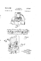
- FIGURE 1 is. a simplified side elevational'view of a typical vertical surface grinding machine witha chuck embodying my invention. mounted thereon;-
- FIGURE 2 is a bottom. planelevation view of the preferred form ofchuck' of'my invention including intersegment stabilizing clamps;
- FIGURE 3* is. a. sectional view takenin the-plane of line 3 3 Of'FIGURE'Z. with the chuck mounted'on the spindle-driven face plate portion of a machine such'as shown in FIGURE'I; I
- FIGURE 4' is a partialv side elevational viewof 'the chuck shown in FIGURES 2 and3;
- FIGURE 5 is. an exploded isometric view of" a circumferential portion of the chuck ofFIGURE 2;
- FIGURE 6 is a side elevational" view of a modifi'ed form of chuck of -my in-ve ntion.
- FIGURE l- is illustrative of the general type of machine with and on which chucks embodying. my invention are useful.
- the machine illustrated is. a vertical surface grinder having abase 9 and a column 10zrising vertically at one-end of base 9; a rotating worktable 11' comprising a circular magnetic chuck 12k and movable laterally on base 9- toward and:away from column- 10; andia driving motor 13-and vertical'spindle Smounted oncolumn-ltl for vertical travel toward and away from worktable 11.
- Spindle S is provided at its lower end with a faceplate F adaptedto receive an annular'chuck shown generally .ing the face plate.
- the preferred form of my invention comprises an annular chuck ring 17 having parallel plane upper and lower annular surfaces 18 and 19, respectively.
- the central opening 20 through chuck ring 17 is bounded by a cylindrical side wall 21 normal to surfaces 18 and 19.
- chuck ring 17 is adapted to be fastened concentrically of and in driving connection with a conventional face plate F on the lower end of and driven by spindle S of a machine tool such as shown in FIGURE 1 by engagement of upper surface 18'with a radially directed annular surface 22 on face plate F and vertical side wall 21 with an axially directed cylindrical shoulder 23 on face plate F coaxial of the spindle S driv- Chuck ring 17 extends radially outwardly of face plate F and is attached to face plate F in any suitable manner as by bolts 24 turned into tapped bores provided around the radially inward periphery of ring 17.
- spindle S is conventionally surrounded by a stationary all) housing H having a stationary coolant inlet fitting C connected by pipe P to a pump and coolant supply tank (not shown).
- An upper annular face of face plate F runs adjacent housing H and coolant inlet fitting C and is provided with an annular distribution channel D.
- Coolant passages K circumferentially spaced in the pe- .a plane annular mounting surface for a plurality of grinding wheel segment holders indicated generally by the reference numeral 25.
- Segment holders 25 are arcuate in plan elevation as seen in FIGURES 2 and 5, conformjing generally to the arcuate shape of widely used conventional arcuate segments of segmented cylindrical grinding wheels.
- the radius of the arc described by each segment holder 25 is generally less than the radius of the outer periphery of chuck ring 17.
- Each segment holder 25 has a plane face 26 adapted to be held against and in surface engagement with plane mounting surface 19 of chuck ring 17.
- Each segment holder 25 is formed with an arcuate open-sided pocket bounded by a generally continuous side wall 27 extending axially outwardly and away from plane face 26 and having circumferentially spaced apart end portions 28 and radially spaced apart side portions 29.
- the circumferentially central portion of each of the side portions 29 extends outwardly and away from plane face 26 a substantially lesser amount than the remainder of side wall 27 to form depression 39 for reasons stated below in connection with the description of the operation of the chuck.
- Each segment holder 25 is adapted to receive one axial end of a grinding wheel segment 15 through the open face of the pocket formed by side wall 27.
- a segment 15 is bottomed in the pocket in relatively loose engagement with side wall 27 and extends outwardly and away from and generally normal to plane face 26 of the segment holder.
- Clamping studs 35 turned in radially directed and tapped bores 36 circumferentially spaced apart on either side of depression 30, preferably in the radially inward side portion 29 of side wall 27, act against the radially inward axial surface of the segment to urge it radially outwardly into tight engagement with radially outward side portion 29 of side wall 27.
- each segment 15 making up a cylindrical grinding wheel is positively positioned and removably held in its own segment holder 25 and in fixed relationship with plane mounting face 26 thereof.
- the means for positioning and removably clamping each segment 15 in a segment holder 25 is individual to each segment and holder and entirely independent of and from the clamping means of the other associated segments and holders of the chuck.
- Segment holders 25 are arranged in circular fashion about and concentric with chuck ring 17 with the plane mounting faces 26 of each in surface engagement with the annular plane mounting surface 19. Segment holders 25 thus form a discontinuous circle of segment holders concentrically located with respect to central opening 20 in chuck ring 17. In so positioning segment holders 25 on chuck ring 17, I prefer to employ appropriately located guide pins 38 and guide pin holes 39 suitably located in plane surface 19 of chuck ring 17 and plane faces 26 of segment holders 25, respectively, or vice versa. Segment holders 25 are removably held in place on chuck ring 17 by means of machine bolts 40 passing through axially directed holes 41 in chuck ring 17 and turned into tapped bores 42 in segment holders 25.
- chuck ring 17 with at least two or more sets of positioning and fastening means such as described above lying along two circles of different diameters and concentric with each other and central opening 20 in chuck ring 17.
- four segment holders 25 are positioned and held in place by and along the inner one of two circles of positioning and fastening means in chuck ring 17.
- the outer one of the two circles of positioning and fastening means is adapted to position and hold five holders 25 like the four shown in FIGURE 2.
- the chuck permits the mounting of cylindrical grinding wheels of two different diameters made up of a single size of holders and segments.
- clamping members 45 and 46 extend longitudinally in a generally circumferential direction with their end portions bearing against the radially inward and outward sidesor faces of adjacent segments 15.
- the clamping members are placed an appropriate distance between the areuate end faces of segments and segment holders 2 5- and are held in position there by suitable clamping means such as machine bolts 47 tending to draw together the central portions of the clamping members spanning the space between adjacent segments.
- clamping elements coact with the interconnected segments to provide a relatively rigid ring of strength adjacent the outboard ends of the segments and away from the segment holders and that is structurally independent of the chuck structure proper but which cooperates with it to stabilize and provide a unitary structural relationship in a cylindrical grinding wheel made up of; relatively long segments.
- a segmented cylindrical grinding wheel is mounted in the chuck of my invention by separately fitting each segment 15 into a segment holder and turning. clamping studs into clamping engagement with pressure-distributing elements 37, segment 15 and an opposite side portion 29 0f side wall 27.
- Each segment 15 is preferably fitted with a segment holder 25 at a work station apart from but convenient to the machine upon which the wheel is to be used. This permits each segment to be carefully and properly seated and clamped in its segment holder 25 and properly referenced with respect to plane face 26 thereof even while the machine on which the wheel is to be used is engaged in productive operations.
- segment holders previously used are being refitted with new or different segments, the holders may be easily and carefully cleaned of grinding residue while apart from and without interruption of the operation of the grinding mashin
- the machine is stopped, the then installed wheel removed by unfastening each of the segment holders 25 from annular chuck ring 17 through theremoval of machine bolts 40.
- the means clamping segments 15 in their respective segment holders 2 5 areundisturbed and only the bolts fastening segment holders 25 to chuck ring 17 need be turned out while chuck ring 17. remains mounted on face plate F.
- coolant passages P and mounting surface 19 of chuck ring 17 may be easily, quickly and eifectively cleaned and relievedof any aocurnulation of residue andgrit produced during the grinding operation. It will be noted that the coolant passages are easily accessible to eye and hand even with chuck ring 17 in place and when segment holders 2 5; are. removed and mounting surface 19 presents a smooth; and easily cleaned annular face insuring the correel: alignment of the next grinding wheel to be mounted and the unhindered, surface engagement between it and plane surface 26 of segments 25 to be installed.
- a new wheel is mounted by separately arranging segments 15 in their mounted condition in segment holders 25 on chuck ring 17 by engaging guide pins38 in guide pinholes 39 and turning bolts 40 through holes 41 in chuck ring 17 into tapped bores 42 in segment holders 25.
- the preferred form of chuck ring 17 is provided with at least two circular sets of guiding and mounting means, which permit the selection of asuitable diameter of cylindrical guiding wheel on the same chuck body and made up of'rnore or fewer holder and segments of one size whereby double cutting may be eliminated on large work areas and. maximum grinding horsepower can be brought to bear on. smaller work areas.
- f5 invention provides for more rapid cleaning and maintenance of the machine and for the proper seating and clamping of segments thereby insuring the correct and true alignment of the segments with respect to each other and their axis of rotation.
- Segments removed from operation are left in their holders 25 and can be reinstalled for use with the same or a dilferent machine in the simple and convenient manner described above Without dressing. Further, the clamping bolts by which segments 15 are mounted and clamped within segment holders 25 need no subsequent tightening or attention.
- the chuck of my invention therefore provides a quick and time-saving apparatus for mounting cylindrical grinding wheels of the'correct one of several different grades andof most suitable diameter on a grinding machine with a minimum loss of time and with an unequaled ease and speed of maintenance.
- a further important advantage of the. chuck of my invention is its action in grinding accidents where a work part being ground rolls between the worktable and grinding wheel.
- Such rolling of the work within the relatively fixed vertical space between the grinding wheel and worktable produces high loads on the ends of each of the grinding wheel segments encountered by the rolling workpiece tending to tip and/ or exert a thrust on the segments tangentially opposite of their direction of movement and inevitably a side thrust onthe spindle of the grinding machine.
- the rolling and tippingerrant workpiece can be removed quickly and/ or the machine stopped, serious damage invariably results to the grinding machine involving a bent spindle and/ or a broken face plate, both of which are costly to repair in terms of time and money.
- segment holders are separate and distinct from each other, they may separately give in and yield to such forces by peeling away from the mountingv surface of the chuck ring, perhaps stripping the threads acting to hold the segments to the chuck ring. and otherwise generally deforming 'Ifhe peeling action and longitudinal bending and curling of the segment holders involved is intentionally encouraged-um der these circumstances through the provision of depressions 30 in side portions. 29 of side wall 27.
- the deformation and yielding of the segment holders is oftenrsufiicient and. generally in suchra direction as torelease the segment from its clamped position inthe affected segment holder, thereby. further reducing the interference between the chuck. andworktable andpreventing or reducing the transmission of deleterious loads to the spindle and face plate of the machine.
- the intersegment stabilizingclamps need not be used. Indeed, their use with'new and longer segments is optional.
- segment holders 50 are completely interchangeable with segment holders 25 described above, being mounted in the same manner to chuck ring 17 and differing only in the depth of their open face pockets as provided by their side walls 51 of reduced height.
- the overall vertical height occupied by the chuck can be reduced in order to utilize more fully grinding wheel segments worn to the point where they may be no longer useful in conventional chucks of fixed vertical dimension as well as to increase the vertical height capacity of the machine.
- Segments 15 are clamped and held in segment holders St in the same manner as in segment holders 25 and, While very similar to segment holders 25, they make possible substantial advantages in grinding wheel operations and their use is possible because of the separability and interchangeability features of the chuck of my invention. 7
- FIGURE 6 A further important feature of my invention is illustrated in FIGURE 6 in connection with the modified form of segment holder 50 shown therein.
- This feature comprises a radially reduced circumferentially central portion as provided by tangentially oriented plane surface 52 on the radially outward side of each segment holder 50.
- Surface 52 of each segment holder 50 lies generally along the chord of the are described by the radially outward side of the segment holder and as such and together with the central portion of reduced vertical height in the radially outward side wall of the segment holder limits the gross radial extension of the segment holder to a point radially inwardly of the radially outward periphery of the segments mounted therein.
- This feature permits grinding to shoulders extending vertically a distance substantially equal to the vertical distance of the mounting surface 19 of chuck ring 17 from the surface being ground when the segment holders are mounted on the inner of the two circles of mounting and fastening means in chuck ring 17.
- this feature permits grinding to shoulders extending vertically above the surface being ground to a height even greater than mounting surface 19 of chuck ring 17 and by and alongside the radially outward periphery of chuck ring 17.
- the chuck of my invention equipped with segment holders having a radially relieved portion as provided by tangentially oriented plane surfaces 52 permits grinding to shoulders on any work that can be accommodated on the machine upon which the chuck is being used and without interference from the chuck.
- a chuck for positioning and holding the grinding wheel for rotation about its axis and for providing a rotatable driving connection between the grinding wheel and the spindledriven face plate, said chuck comprising Cir amiss;
- annular chuck ring adapted to be fastened concen trically of and in driving connection with the face plate and having an annular mounting surface facing away from and of greaterradial extent than the face plate
- a plurality of individual segment holding means arranged in discontinuous circular fashion about said annular mounting surface of said chuck ring forrespectively receiving and holding one axial end of each or" the grinding wheel segments independently of said chuck ring and for collectively positioning the segments in a generally cylindrical form extendoutwardly and away from said annular mounting surface and having an axis in alignment with the axis of said chuck ring.
- clamping means individually associated with each segment holding means and independent of said chuck ring for removably fastening and holding a segment within said holding means
- each of said segment holding means has a circumferentially central portion of reduced vertical dimension yieldable under high tangentially directed loads on the outward end of a segment held by said holding means so as to tend to prevent the transmission of such loads from the segment through the chuck ring to an interconnected spindle-driven face plate.
- each of said segment holding means has a circumferentially central portion of reduced radial dimension extending radially a lesser amount than the outer periphery of a segmented cylindrical grinding wheel mounted therein.
- a chuck for positioning and holding a segmented cylindrical grinding wheel for rotation about its axis and for providing a rotatable driving connection between the grinding wheel and a spindle-driven face plate, said chuck 0 comprising an annular chuck ring adapted to be fastened concentrically of and in driving connection with the face plate and having a flat annular mounting surface in a substantially radial plane facing away from the face plate,
- each of said segment holders for holding the individual segments of a segmented cylindrical grinding wheel, each of said holders having a plane face and a pocket having an open side facing oppositely from said plane face for receiving one axial end portion of a grinding wheel segment with the segment extending axially and outwardly therefrom, each of said segment holders comprises a continuous side wall extending outwardly and away from said plane surface and bounding said pocket and having circumferentially spaced end portions and radially spaced side portions, the circumferentially central part of said side portions extending from said plane surface a lesser amount than the rest of said side wall and yieldable under sudden high tangentially directed loads on the outward end of a segment held by said segment holders so as to tend to prevent the transmission of such loads from the segment through the chuck ring to an interconnected spindle-driven face plate, said plurality of holders being arranged in generally circular fashion on and coaxially of said chuck ring with said plane face of each of said holders in surface engagement with said annular mounting surface of said chuck ring and
- a chuck for holding a grinding wheel made up of a plurality of grinding segments and comprising an annular mounting ring and a plurality of grinding segment holder said mounting ring having opposite annular faces, one
- segment holders each having separate and independent segment-holding means for clamping and holding a grinding segment therein
- each of said segment holders in a generally circular arrangement on said segment holder mounting surface of said ring, said means being carried solely in that portion of said mounting ring of greater radial extent than said mounting ring surface.
- each of said segment holding means has a circumferentially central portion of reduced vertical dimension yieldable under high tangentially directed loads on the outward end of a segment held by said holding means.
- each of said segments being removably and independently fastened in one of said segment holders and said intersegment stabilizing means interconnecting the radially opposite faces of the outboard ends of adjacent segments of said cylindrical grinding Wheel, said stabilizing means being circumferentially discontinuous from each other.
- a chuck comprising an annular mounting ring and a plurality of segment holders
- each of said segments being removably and independently fastened in one of said segment holders and said segment holders being arranged in a circle on said mounting ring and each separately and removably fastened thereto so that said segments collectively form a segmented cylindrical grinding wheel, each of said segment holders having a circumferentially central portion of reduced dimension yieldable under high tangentially directed loads on the outward end of a segment held thereby,
Landscapes
- Engineering & Computer Science (AREA)
- Mechanical Engineering (AREA)
- Grinding Of Cylindrical And Plane Surfaces (AREA)
Description
March 2, 1965 A. s. HOWARD 3,171,237
GRINDING WHEEL CHUCK Filed Sept. 20, 1962 2 Sheets-Shqet l INVENTOR ALF/e50 S Hon A120 BY @swmi 5 5m ATTORNEYS.
March 2, 1965 s. owA 3,171,237
GRINDING WHEEL CHUCK Filed Sept. 20, 1962 2 Sheets-Sheet 2 hill I l ATTORNEYS.
United States Patent 3,171,237 GRENDING WHEEL CHUCK Alfred S. Howard, 15830 Van AkenBlvd Shaker Heights 2%, Ohio Fiied ept. 20, W62, Ser. No. 225,059 8 Claims. (61. 51-209) This invention relates to chucks and more particularly to chucks for segmented grinding wheels as used, for ex ample, in vertical surface grinders.
The use of arcuate blocks of grinding material arranged in circular fashion to form a segmented cylindrical grindous annular end face of the cylindrical arrangement of grinding segments. During the grinding operation, coolant is pumped from a tank and supplied to the inside of the chuck and grinding wheel through circumferentially spaced ports in the face plate.
Known chucks for segmented cylindrical grinding wheels are of a unitary annular form adapted to be suitably andmoreor less permanently secured to the spindle-driven face plate of a grinding machine. Such chucks are provided with a number of arcuate pockets formed therein and arranged in a circle of fixed diameter and opening on that face of the chuck opposite the face plate. Various holding or clamping arrangements are provided for securing the segments making up the discontinuous cylindrical grinding wheel in the pockets of the chuck.
In chucks such as generally described above, the removal and replacing of worn wheels or the changing of the grade of wheel involves the removal of eachsegment from its pocket and the attendant manipulation of its clamping apparatus, the cleaning of chips and grinding residue from each pocket, the insertion and. correct seating of each new segment in a pocket of. the chuck, the manipulation of the clamping means associated witheach segment for adequately securing the segment in. place, and finally dressing the wheel after all of the segments are in place, It will be apparent that the changing of a segmented grinding wheel in, such a unitary annular chuck mounted on the downwardly facing surfaw of a face plate driven by a vertical spindle is a difficult and time-consuming job andrepresents a substantialamount of lost production time for the relatively expensive machine in which the grinding wheel chuck is being used. Further, machine maintenance and cleaning, especially of the coolant ports in the face plate on the inside of; the cylindrical chuck and wheel, are ditficult andtime-consuming. Such chucks are heavy and expensive and are be practical because of the economic cost of stocking of even a few more than one chuck. per machine and the labor and time required to change them. Thus the above-described procedure is the accepted andconventional way of changing grinding wheels held by such chucks.
Another disadvantage of such, chucks is encountered in connection with grinding accidents in which the part being ground rolls or tilts between the table and the chuck. Because the segments are securely held in pockets of the unitary chuck ring, such accidents frequently result in broken face plates and/or bent spindles necessitating costly repairs and loss of production time.
A further disadvantage is found in the fixed diametrical dimensions of the conventional or unitary annular chuck. If work is being performed on a large piece of work on 3,171,237 Fatented Mar. 2, 1965 a machinehaving a chuck of too small adiameter, double cutting is necessary; and, if the particular chuck with which the machine is equipped is larger than necessary for the size of the Work, the maximum grinding horsepower of the machine cannot be utilized.
Conventional chucks such as I- have described above and having a portion or portions of the structure of the chuck extending radially outwardly ofthe grinding wheel segments mounted in it do not permit grinding to vertically extending shoulders whose height is greater than the distance which the segments extend beyond the-chuck.
It is an object of my invention, therefore, to-provide a chuck for segmented cylindrical grinding wheels which overcomes the several disadvantages of chucks of similar purpose but of substantially different structure and operation and such as described above.
In particular, an object of my invention is to provide such a chuck that makes possible the easy and rapid removal and/or replacement of wheelsegments from and/or on the chuck, that permitsan increased ease of maintenance with less lost production time than that encountered with other chucks, that is safer in theevent of an accident and tends to prevent costly damage to the machine driving the chuck, that permits variation in the. diameter of thecylindrical grinding wheel mounted thereon and thus reduces the amount of double cutting required and maximizes the horsepower delivered to the work while reducing, if not eliminating, thestocking of a large number of chucks of various sizes and correspondingsizes of grinding wheel segments, and which increases the height of workpiece capacity which the machine driving the chuck wheel will accominodate and which permits grinding to shoulders having avertical height above the surface being ground greater than the length of the segment extending from the chuck.
A further object is to provide cooperating accessory clamping means for use with the chuck in-stabilizing the outward ends of segments which are new and/oronly partially used and extend outwardly of the chuck a relatively great distance. 7
The foregoingv objects and advantages and the means and'manner of their accomplishments will becomeapparent from the following description of a preferred and modified form of chuck embodying my invention taken together with the accompanying drawings inwhich:
FIGURE 1 is. a simplified side elevational'view ofa typical vertical surface grinding machine witha chuck embodying my invention. mounted thereon;-
FIGURE 2 is a bottom. planelevation view of the preferred form ofchuck' of'my invention including intersegment stabilizing clamps;
FIGURE 3*is. a. sectional view takenin the-plane of line 3 3 Of'FIGURE'Z. with the chuck mounted'on the spindle-driven face plate portion of a machine such'as shown in FIGURE'I; I
FIGURE 4' is a partialv side elevational viewof 'the chuck shown in FIGURES 2 and3;
FIGURE 5 is. an exploded isometric view of" a circumferential portion of the chuck ofFIGURE 2; and
FIGURE 6 is a side elevational" view of a modifi'ed form of chuck of -my in-ve ntion.
FIGURE l-is illustrative of the general type of machine with and on which chucks embodying. my invention are useful. The machine illustrated is. a vertical surface grinder having abase 9 and a column 10zrising vertically at one-end of base 9; a rotating worktable 11' comprising a circular magnetic chuck 12k and movable laterally on base 9- toward and:away from column- 10; andia driving motor 13-and vertical'spindle Smounted oncolumn-ltl for vertical travel toward and away from worktable 11. Spindle S is provided at its lower end with a faceplate F adaptedto receive an annular'chuck shown generally .ing the face plate.
at 14 in which are mounted a number of segments 15 arranged to collectively form a discontinuous cylindrical grinding wheel. Motor 13, by connection through the spindle-driven face plate F, rotates chuck 14 and its segmented cylindrical grinding wheel mounted therein about its axis. The direction of rotation of chuck 14 is general-1y opposite to and at a substantially higher speed than the direction of rotation and speed of worktable 11. A piece of work W is held by magnetic chuck 12 on worktable 11. In operation, motor 13 together with chuck 14 holding grinding wheel segments 15 is moved vertically on column until suitable engagement according to conventional practice is made between the downwardly facing annular face of the cylindrical grinding wheel and the upwardly facing surface of work W with worktable 11 and chuck 14 rotating in the manner described above.
More particularly and as seen in FIGURES 2 through 5, the preferred form of my invention comprises an annular chuck ring 17 having parallel plane upper and lower annular surfaces 18 and 19, respectively. The central opening 20 through chuck ring 17 is bounded by a cylindrical side wall 21 normal to surfaces 18 and 19. As seen in FIGURE 3, chuck ring 17 is adapted to be fastened concentrically of and in driving connection with a conventional face plate F on the lower end of and driven by spindle S of a machine tool such as shown in FIGURE 1 by engagement of upper surface 18'with a radially directed annular surface 22 on face plate F and vertical side wall 21 with an axially directed cylindrical shoulder 23 on face plate F coaxial of the spindle S driv- Chuck ring 17 extends radially outwardly of face plate F and is attached to face plate F in any suitable manner as by bolts 24 turned into tapped bores provided around the radially inward periphery of ring 17.
Though forming no part of my invention, it is helpful to anunderstanding thereof to describe briefly a conventional and typical spindle, face plate and coolant arrangement and their relationship to each other and the chuck embodying my invention. As seen in FIGURE 3, spindle S is conventionally surrounded by a stationary all) housing H having a stationary coolant inlet fitting C connected by pipe P to a pump and coolant supply tank (not shown). An upper annular face of face plate F runs adjacent housing H and coolant inlet fitting C and is provided with an annular distribution channel D.
Coolant passages K circumferentially spaced in the pe- .a plane annular mounting surface for a plurality of grinding wheel segment holders indicated generally by the reference numeral 25. Segment holders 25 are arcuate in plan elevation as seen in FIGURES 2 and 5, conformjing generally to the arcuate shape of widely used conventional arcuate segments of segmented cylindrical grinding wheels. The radius of the arc described by each segment holder 25 is generally less than the radius of the outer periphery of chuck ring 17. Each segment holder 25 has a plane face 26 adapted to be held against and in surface engagement with plane mounting surface 19 of chuck ring 17. Each segment holder 25 is formed with an arcuate open-sided pocket bounded by a generally continuous side wall 27 extending axially outwardly and away from plane face 26 and having circumferentially spaced apart end portions 28 and radially spaced apart side portions 29. The circumferentially central portion of each of the side portions 29 extends outwardly and away from plane face 26 a substantially lesser amount than the remainder of side wall 27 to form depression 39 for reasons stated below in connection with the description of the operation of the chuck.
Each segment holder 25 is adapted to receive one axial end of a grinding wheel segment 15 through the open face of the pocket formed by side wall 27. A segment 15 is bottomed in the pocket in relatively loose engagement with side wall 27 and extends outwardly and away from and generally normal to plane face 26 of the segment holder. Clamping studs 35 turned in radially directed and tapped bores 36 circumferentially spaced apart on either side of depression 30, preferably in the radially inward side portion 29 of side wall 27, act against the radially inward axial surface of the segment to urge it radially outwardly into tight engagement with radially outward side portion 29 of side wall 27. I prefer to employ pressure-distributing elements 37 at the point of engagement between the ends of clamping studs 35 and the radially inward surface of each segment 15. In this manner, each segment 15 making up a cylindrical grinding wheel is positively positioned and removably held in its own segment holder 25 and in fixed relationship with plane mounting face 26 thereof. The means for positioning and removably clamping each segment 15 in a segment holder 25 is individual to each segment and holder and entirely independent of and from the clamping means of the other associated segments and holders of the chuck.
I prefer to provide chuck ring 17 with at least two or more sets of positioning and fastening means such as described above lying along two circles of different diameters and concentric with each other and central opening 20 in chuck ring 17. As shown in FIGURE 2, four segment holders 25 are positioned and held in place by and along the inner one of two circles of positioning and fastening means in chuck ring 17. The outer one of the two circles of positioning and fastening means is adapted to position and hold five holders 25 like the four shown in FIGURE 2. Thus, the chuck permits the mounting of cylindrical grinding wheels of two different diameters made up of a single size of holders and segments. The advantages of the multiple sets of positioning and fastening means for segments 25 in chuck ring 17 will be apparent in connection with the following description of the operation of the chuck.
When new or relatively unworn grinding wheel segments are fitted in the chuck of my invention and as described above, the segments are axially as much as six inches long and extend outwardly of segment holders 25 a substantial distance. I have discovered that the action of a segmented cylindrical grinding wheel held in the chuck can be substantially improved under these conditions by employing an accessory element comprising an intersegment stabilizing clamp interconnecting the outboard ends of adjacent segments.
:ward and outward clamping members 45 and 46, respectively. Qlamping members 45 and 46 extend longitudinally in a generally circumferential direction with their end portions bearing against the radially inward and outward sidesor faces of adjacent segments 15. The clamping members are placed an appropriate distance between the areuate end faces of segments and segment holders 2 5- and are held in position there by suitable clamping means such as machine bolts 47 tending to draw together the central portions of the clamping members spanning the space between adjacent segments.
All: of the clamping elements coact with the interconnected segments to provide a relatively rigid ring of strength adjacent the outboard ends of the segments and away from the segment holders and that is structurally independent of the chuck structure proper but which cooperates with it to stabilize and provide a unitary structural relationship in a cylindrical grinding wheel made up of; relatively long segments.
In operation, a segmented cylindrical grinding wheel is mounted in the chuck of my invention by separately fitting each segment 15 into a segment holder and turning. clamping studs into clamping engagement with pressure-distributing elements 37, segment 15 and an opposite side portion 29 0f side wall 27. Each segment 15 is preferably fitted with a segment holder 25 at a work station apart from but convenient to the machine upon which the wheel is to be used. This permits each segment to be carefully and properly seated and clamped in its segment holder 25 and properly referenced with respect to plane face 26 thereof even while the machine on which the wheel is to be used is engaged in productive operations. If segment holders previously used are being refitted with new or different segments, the holders may be easily and carefully cleaned of grinding residue while apart from and without interruption of the operation of the grinding mashin When; all of the segments 15 to be employed have been mountedin a segment holder 25, the machine is stopped, the then installed wheel removed by unfastening each of the segment holders 25 from annular chuck ring 17 through theremoval of machine bolts 40. It will be noted that in demounting a grinding wheel from a machine, the means clamping segments 15 in their respective segment holders 2 5 areundisturbed and only the bolts fastening segment holders 25 to chuck ring 17 need be turned out while chuck ring 17. remains mounted on face plate F.
With all of segment holders 25 and segments 15 which they; hold removed from chuck ring 17, face plate F, coolant passages P and mounting surface 19 of chuck ring 17 may be easily, quickly and eifectively cleaned and relievedof any aocurnulation of residue andgrit produced during the grinding operation. It will be noted that the coolant passages are easily accessible to eye and hand even with chuck ring 17 in place and when segment holders 2 5; are. removed and mounting surface 19 presents a smooth; and easily cleaned annular face insuring the correel: alignment of the next grinding wheel to be mounted and the unhindered, surface engagement between it and plane surface 26 of segments 25 to be installed.
A new wheel is mounted by separately arranging segments 15 in their mounted condition in segment holders 25 on chuck ring 17 by engaging guide pins38 in guide pinholes 39 and turning bolts 40 through holes 41 in chuck ring 17 into tapped bores 42 in segment holders 25. The preferred form of chuck ring 17 is provided with at least two circular sets of guiding and mounting means, which permit the selection of asuitable diameter of cylindrical guiding wheel on the same chuck body and made up of'rnore or fewer holder and segments of one size whereby double cutting may be eliminated on large work areas and. maximum grinding horsepower can be brought to bear on. smaller work areas.
It will; be apparentthat a minimum of down time is required to remove and replace a grinding wheel when a chuck embodying my invention is employed. Further, my
f5 invention provides for more rapid cleaning and maintenance of the machine and for the proper seating and clamping of segments thereby insuring the correct and true alignment of the segments with respect to each other and their axis of rotation.
Segments removed from operation are left in their holders 25 and can be reinstalled for use with the same or a dilferent machine in the simple and convenient manner described above Without dressing. Further, the clamping bolts by which segments 15 are mounted and clamped within segment holders 25 need no subsequent tightening or attention. The chuck of my invention therefore provides a quick and time-saving apparatus for mounting cylindrical grinding wheels of the'correct one of several different grades andof most suitable diameter on a grinding machine with a minimum loss of time and with an unequaled ease and speed of maintenance.
A further important advantage of the. chuck of my invention is its action in grinding accidents where a work part being ground rolls between the worktable and grinding wheel. Such rolling of the work within the relatively fixed vertical space between the grinding wheel and worktable produces high loads on the ends of each of the grinding wheel segments encountered by the rolling workpiece tending to tip and/ or exert a thrust on the segments tangentially opposite of their direction of movement and inevitably a side thrust onthe spindle of the grinding machine. Unless the rolling and tippingerrant workpiece can be removed quickly and/ or the machine stopped, serious damage invariably results to the grinding machine involving a bent spindle and/ or a broken face plate, both of which are costly to repair in terms of time and money.
When such a grinding accident occurs in a machine employing a chuck embodying my invention, the loads applied to the grinding wheel segments tend not to be transmitted to the machine spindle and face plate by virtue of the deformation and yielding of separate and individual ones of the segment holders comprising the chuck. As one or another of the outboard ends of the grinding wheel segments encounters artipped or rolled workpiece during the. counter-rotation of worktable and grinding wheel, a thrust tangentially directed with respect to the circular path of travel of the segments is applied totheiroutboard ends. tending to both tip them and their respective segment holder and the plane surface of; the segmentholder out of engagement with the chuck ring. Because the segment holders are separate and distinct from each other, they may separately give in and yield to such forces by peeling away from the mountingv surface of the chuck ring, perhaps stripping the threads acting to hold the segments to the chuck ring. and otherwise generally deforming 'Ifhe peeling action and longitudinal bending and curling of the segment holders involved is intentionally encouraged-um der these circumstances through the provision of depressions 30 in side portions. 29 of side wall 27. The deformation and yielding of the segment holders is oftenrsufiicient and. generally in suchra direction as torelease the segment from its clamped position inthe affected segment holder, thereby. further reducing the interference between the chuck. andworktable andpreventing or reducing the transmission of deleterious loads to the spindle and face plate of the machine. At the same time, because each segment is independently clamped and heldin position in the chuck, accidents causing the loss of one segment do not carry the reaction around the chuck and throw off all of the segments mounted thereon as in chucks where common clampsare employed to hold adjacent segments. Upon the occurrence of such a grinding accident, the wheel may be easily and quickly repaired and placed back in operation because of the easy and'separate removability of each holder and segment.
As the segments making up the cylindrical. grinding wheel become. axially shorter inlength through use, the intersegment stabilizingclamps need not be used. Indeed, their use with'new and longer segments is optional.
. a To further increase the useful life of worn grinding wheel segments, I prefer to employ segment holders indicated generally by reference numeral 50 as shown in FIGURE 6. Segment holders 50 are completely interchangeable with segment holders 25 described above, being mounted in the same manner to chuck ring 17 and differing only in the depth of their open face pockets as provided by their side walls 51 of reduced height. Thus through the chuck of my invention, the overall vertical height occupied by the chuck can be reduced in order to utilize more fully grinding wheel segments worn to the point where they may be no longer useful in conventional chucks of fixed vertical dimension as well as to increase the vertical height capacity of the machine. Segments 15 are clamped and held in segment holders St in the same manner as in segment holders 25 and, While very similar to segment holders 25, they make possible substantial advantages in grinding wheel operations and their use is possible because of the separability and interchangeability features of the chuck of my invention. 7
A further important feature of my invention is illustrated in FIGURE 6 in connection with the modified form of segment holder 50 shown therein. This feature comprises a radially reduced circumferentially central portion as provided by tangentially oriented plane surface 52 on the radially outward side of each segment holder 50. Surface 52 of each segment holder 50 lies generally along the chord of the are described by the radially outward side of the segment holder and as such and together with the central portion of reduced vertical height in the radially outward side wall of the segment holder limits the gross radial extension of the segment holder to a point radially inwardly of the radially outward periphery of the segments mounted therein. This feature permits grinding to shoulders extending vertically a distance substantially equal to the vertical distance of the mounting surface 19 of chuck ring 17 from the surface being ground when the segment holders are mounted on the inner of the two circles of mounting and fastening means in chuck ring 17. When the segment holders are arranged along and around the radially outward circle of positioning and fastening means in chuck ring 17, this feature permits grinding to shoulders extending vertically above the surface being ground to a height even greater than mounting surface 19 of chuck ring 17 and by and alongside the radially outward periphery of chuck ring 17. Thus, the chuck of my invention equipped with segment holders having a radially relieved portion as provided by tangentially oriented plane surfaces 52 permits grinding to shoulders on any work that can be accommodated on the machine upon which the chuck is being used and without interference from the chuck.
While I have described this feature of my invention in connection with the modified form of segment holder 5i shown in FIGURE 6, it will be readily apparent that the feature is equally useful and provides the same advantages when employed in connection with segment holders 25 such as shown in FIGURES 2, 3, 4 and 5 of the drawings and its use is not limited to the modified form of segment holders 50 as shown in FIGURE 6 of the drawings.
Changes, modifications and improvements may be made to the above-described preferred and modified forms of my invention without departing from the precepts and principles of the invention. Therefore, I do not wish my patent to be limited to any particular form of my invention specifically illustrated and described nor in any manner inconsistent with the extent to which my invention has promoted the art.
I claim:
1. In combination with a spindle-driven face plate of limited radial extent and a segmented grinding wheel, a chuck for positioning and holding the grinding wheel for rotation about its axis and for providing a rotatable driving connection between the grinding wheel and the spindledriven face plate, said chuck comprising Cir amiss;
an annular chuck ring adapted to be fastened concen trically of and in driving connection with the face plate and having an annular mounting surface facing away from and of greaterradial extent than the face plate,
a plurality of individual segment holding means arranged in discontinuous circular fashion about said annular mounting surface of said chuck ring forrespectively receiving and holding one axial end of each or" the grinding wheel segments independently of said chuck ring and for collectively positioning the segments in a generally cylindrical form extendoutwardly and away from said annular mounting surface and having an axis in alignment with the axis of said chuck ring.
clamping means individually associated with each segment holding means and independent of said chuck ring for removably fastening and holding a segment within said holding means,
mounting means carried in said ring solely radially outwardly of the radial extent of the face plate for separately fastening in driving connection each-of said segment holding means to said chuck ring and permitting the separate removal from and replacement on said chuck ring of each of said segment hold.- ing means with a grinding wheel segment held therein and while said ring is mounted on the face plate.
2. Apparatus according to claim 1 in which each of said segment holding means has a circumferentially central portion of reduced vertical dimension yieldable under high tangentially directed loads on the outward end of a segment held by said holding means so as to tend to prevent the transmission of such loads from the segment through the chuck ring to an interconnected spindle-driven face plate.
3. Apparatus according to claim 2 in which each of said segment holding means has a circumferentially central portion of reduced radial dimension extending radially a lesser amount than the outer periphery of a segmented cylindrical grinding wheel mounted therein.
4. A chuck for positioning and holding a segmented cylindrical grinding wheel for rotation about its axis and for providing a rotatable driving connection between the grinding wheel and a spindle-driven face plate, said chuck 0 comprising an annular chuck ring adapted to be fastened concentrically of and in driving connection with the face plate and having a flat annular mounting surface in a substantially radial plane facing away from the face plate,
a plurality of individual segment holders for holding the individual segments of a segmented cylindrical grinding wheel, each of said holders having a plane face and a pocket having an open side facing oppositely from said plane face for receiving one axial end portion of a grinding wheel segment with the segment extending axially and outwardly therefrom, each of said segment holders comprises a continuous side wall extending outwardly and away from said plane surface and bounding said pocket and having circumferentially spaced end portions and radially spaced side portions, the circumferentially central part of said side portions extending from said plane surface a lesser amount than the rest of said side wall and yieldable under sudden high tangentially directed loads on the outward end of a segment held by said segment holders so as to tend to prevent the transmission of such loads from the segment through the chuck ring to an interconnected spindle-driven face plate, said plurality of holders being arranged in generally circular fashion on and coaxially of said chuck ring with said plane face of each of said holders in surface engagement with said annular mounting surface of said chuck ring and said pockets of said holders facing outwardly and away from said mounting surface, means individually associated with each holder for removably fastening a segment within said pocket,
means for separately fastening in driving connection each of said segment holders to said chuck ring and permitting the separate removal from and replacement on said chuck ring of each of said segment holders.
5. A chuck for holding a grinding wheel made up of a plurality of grinding segments and comprising an annular mounting ring and a plurality of grinding segment holder said mounting ring having opposite annular faces, one
of said faces having an annular ring mounting surface of limited radial extent for mounting and locating engagement of said ring, the other of said faces having a segment holder mounting surface of greater radial extent than said ring mounting surface for mounting said segment holders,
said segment holders each having separate and independent segment-holding means for clamping and holding a grinding segment therein,
means for separately and removably fastening each of said segment holders in a generally circular arrangement on said segment holder mounting surface of said ring, said means being carried solely in that portion of said mounting ring of greater radial extent than said mounting ring surface.
6. Apparatus according to claim in which each of said segment holding means has a circumferentially central portion of reduced vertical dimension yieldable under high tangentially directed loads on the outward end of a segment held by said holding means.
7. In combination with a cylindrical grinding wheel comprising a plurality of segments, a chuck comprising an annular mounting ring, a plurality of segment holders and intersegment stabilizing means,
each of said segments being removably and independently fastened in one of said segment holders and said intersegment stabilizing means interconnecting the radially opposite faces of the outboard ends of adjacent segments of said cylindrical grinding Wheel, said stabilizing means being circumferentially discontinuous from each other.
8. In combination with a cylindrical grinding wheel comprising a plurality of segments, a chuck comprising an annular mounting ring and a plurality of segment holders,
each of said segments being removably and independently fastened in one of said segment holders and said segment holders being arranged in a circle on said mounting ring and each separately and removably fastened thereto so that said segments collectively form a segmented cylindrical grinding wheel, each of said segment holders having a circumferentially central portion of reduced dimension yieldable under high tangentially directed loads on the outward end of a segment held thereby,
the radially outermost portions of said segment holders lying radially inwardly of the radially outermost portions of said segments.
References Cited in the file of this patent UNITED STATES PATENTS 970,618 Gardner Sept. 20, 1910 1,892,434 Larsson Dec. 27, 1932 2,111,955 Akans Mar. 22, 1938 2,541,844 Titcomb Feb. 13, 1951 2,720,733 Ballash Oct. 18, 1955 2,867,063 Metzger Jan. 6, 1959
Claims (1)
- 8. IN COMBINATION WITH A CYLINDRICAL GRINDING WHEEL COMPRISING A PLURALITY OF SEGMENTS, A CHUCK COMPRISING AN ANNULAR MOUNTING RING AND A PLURALITY OF SEGMENT HOLDERS, EACH OF SAID SEGMENTS BEING REMOVABLY AND INDEPENDENTLY FASTENED IN ONE OF SAID SEGMENT HOLDERS AND SAID SEGMENT HOLDER BEING ARRANGED IN A CIRCLE ON SAID MOUNTING RING AND EACH SEPARATELY AND REMOVABLY FASTENED THERETO SO THAT SAID SEGMENTS COLLECTIVELY FORM A SEGMENTED CYLINDRICAL GRINDING WHEEL, EACH OF SAID SEGMENT HOLDERS HAVING A CIRCUMFERENTIALLY CENTRAL PORTION OF REDUCED DIMENSION YIELDABLE UNDER HIGH TANGENTIALLY DIRECTED LOADS ON THE OUTWARD END OF A SEGMENT HELD THEREBY, THE RADIALLY OUTERMOST PORTIONS OF SAID SEGMENTS HOLDERS LYING RADIALLY INWARDLY OF THE RADIALLY OUTERMOST PORTIONS OF SAID SEGMENTS.
Priority Applications (1)
| Application Number | Priority Date | Filing Date | Title |
|---|---|---|---|
| US225059A US3171237A (en) | 1962-09-20 | 1962-09-20 | Grinding wheel chuck |
Applications Claiming Priority (1)
| Application Number | Priority Date | Filing Date | Title |
|---|---|---|---|
| US225059A US3171237A (en) | 1962-09-20 | 1962-09-20 | Grinding wheel chuck |
Publications (1)
| Publication Number | Publication Date |
|---|---|
| US3171237A true US3171237A (en) | 1965-03-02 |
Family
ID=22843355
Family Applications (1)
| Application Number | Title | Priority Date | Filing Date |
|---|---|---|---|
| US225059A Expired - Lifetime US3171237A (en) | 1962-09-20 | 1962-09-20 | Grinding wheel chuck |
Country Status (1)
| Country | Link |
|---|---|
| US (1) | US3171237A (en) |
Cited By (10)
| Publication number | Priority date | Publication date | Assignee | Title |
|---|---|---|---|---|
| US3510993A (en) * | 1967-11-14 | 1970-05-12 | Norton Co | Segmental grinding wheel |
| US3524736A (en) * | 1968-10-10 | 1970-08-18 | Pneumo Dynamics Corp | Grinding segment and holder therefor |
| US4209950A (en) * | 1976-11-13 | 1980-07-01 | Hans Sielemann | Grinding machine |
| US4224768A (en) * | 1978-12-05 | 1980-09-30 | The United States Of America As Represented By The Secretary Of The Air Force | Apparatus for, and method of, plunge grinding |
| US4961290A (en) * | 1983-01-13 | 1990-10-09 | Blanchard Abrasives, Inc. | Mount for grinding wheel |
| US5779528A (en) * | 1996-07-12 | 1998-07-14 | Norton Company | Elastomeric mount for grinding wheel, and grinder |
| EP1361021A1 (en) * | 2002-05-10 | 2003-11-12 | Michael Müller | Polishing device with a recess formed around the rotational axis |
| US20110009037A1 (en) * | 2008-02-27 | 2011-01-13 | Toyota Jidosha Kabushiki Kaisha | Polishing apparatus |
| US20110124273A1 (en) * | 2009-11-23 | 2011-05-26 | Samsung Electronics Co., Ltd. | Wafer polishing apparatus for adjusting height of wheel tip |
| EP4659898A1 (en) * | 2024-06-05 | 2025-12-10 | Siti - B&T Group S.p.A. | Abrasive assembly for the surface machining of ceramic and/or stone manufactured articles |
Citations (6)
| Publication number | Priority date | Publication date | Assignee | Title |
|---|---|---|---|---|
| US970618A (en) * | 1908-01-31 | 1910-09-20 | Roland Gardner | Abrading-wheel. |
| US1892434A (en) * | 1926-06-12 | 1932-12-27 | Norton Co | Segmental grinding wheel |
| US2111955A (en) * | 1936-08-27 | 1938-03-22 | William R Akans | Grinding and polishing apparatus |
| US2541844A (en) * | 1949-07-12 | 1951-02-13 | Titcomb Albert Shepard | Abrasive wheel |
| US2720733A (en) * | 1953-12-14 | 1955-10-18 | Sterling Grinding Wheel Co | Grinding wheel |
| US2867063A (en) * | 1956-02-28 | 1959-01-06 | Super Cut | Multiple grinding wheel |
-
1962
- 1962-09-20 US US225059A patent/US3171237A/en not_active Expired - Lifetime
Patent Citations (6)
| Publication number | Priority date | Publication date | Assignee | Title |
|---|---|---|---|---|
| US970618A (en) * | 1908-01-31 | 1910-09-20 | Roland Gardner | Abrading-wheel. |
| US1892434A (en) * | 1926-06-12 | 1932-12-27 | Norton Co | Segmental grinding wheel |
| US2111955A (en) * | 1936-08-27 | 1938-03-22 | William R Akans | Grinding and polishing apparatus |
| US2541844A (en) * | 1949-07-12 | 1951-02-13 | Titcomb Albert Shepard | Abrasive wheel |
| US2720733A (en) * | 1953-12-14 | 1955-10-18 | Sterling Grinding Wheel Co | Grinding wheel |
| US2867063A (en) * | 1956-02-28 | 1959-01-06 | Super Cut | Multiple grinding wheel |
Cited By (11)
| Publication number | Priority date | Publication date | Assignee | Title |
|---|---|---|---|---|
| US3510993A (en) * | 1967-11-14 | 1970-05-12 | Norton Co | Segmental grinding wheel |
| US3524736A (en) * | 1968-10-10 | 1970-08-18 | Pneumo Dynamics Corp | Grinding segment and holder therefor |
| US4209950A (en) * | 1976-11-13 | 1980-07-01 | Hans Sielemann | Grinding machine |
| US4224768A (en) * | 1978-12-05 | 1980-09-30 | The United States Of America As Represented By The Secretary Of The Air Force | Apparatus for, and method of, plunge grinding |
| US4961290A (en) * | 1983-01-13 | 1990-10-09 | Blanchard Abrasives, Inc. | Mount for grinding wheel |
| US5779528A (en) * | 1996-07-12 | 1998-07-14 | Norton Company | Elastomeric mount for grinding wheel, and grinder |
| EP1361021A1 (en) * | 2002-05-10 | 2003-11-12 | Michael Müller | Polishing device with a recess formed around the rotational axis |
| US20110009037A1 (en) * | 2008-02-27 | 2011-01-13 | Toyota Jidosha Kabushiki Kaisha | Polishing apparatus |
| US8460063B2 (en) * | 2008-02-27 | 2013-06-11 | Toyota Jidosha Kabushiki Kaisha | Polishing apparatus |
| US20110124273A1 (en) * | 2009-11-23 | 2011-05-26 | Samsung Electronics Co., Ltd. | Wafer polishing apparatus for adjusting height of wheel tip |
| EP4659898A1 (en) * | 2024-06-05 | 2025-12-10 | Siti - B&T Group S.p.A. | Abrasive assembly for the surface machining of ceramic and/or stone manufactured articles |
Similar Documents
| Publication | Publication Date | Title |
|---|---|---|
| US3171237A (en) | Grinding wheel chuck | |
| KR101002609B1 (en) | Grinding method and apparatus for rotating symmetrical mechanical parts | |
| US2565590A (en) | Lapping machine | |
| US3777443A (en) | Segmented griding wheel | |
| US2323091A (en) | Chuck | |
| GB1222805A (en) | Improvements in or relating to grinding machines for internally grinding ring-shaped workpieces | |
| US4361061A (en) | Machine tool for dressing the end face of an engine cylinder liner | |
| US3090105A (en) | Crushing roll construction | |
| US2414811A (en) | Cemented carbide cutting tool | |
| US1808288A (en) | Work holder | |
| US2510113A (en) | Machine for grinding lenses | |
| USRE23937E (en) | Lapping machine | |
| US2720733A (en) | Grinding wheel | |
| US1017880A (en) | Grinding-machine. | |
| US4525956A (en) | In-situ annular face grinder | |
| CN210360879U (en) | Clamping tool for grinding polygonal punch | |
| US2291073A (en) | Knife grinder | |
| US2541873A (en) | Lens grinding tool and method | |
| US2786312A (en) | Work forming apparatus | |
| US2089847A (en) | Grinding wheel | |
| US2303459A (en) | Surface grinding fixture | |
| US2653423A (en) | Apparatus for lapping connecting rod ends, caps and similar articles | |
| US1439017A (en) | Device for manufacture of piston rings | |
| US2159288A (en) | Work centering and holding machine | |
| US4048762A (en) | Segmented grinding wheel |