US3151663A - Inflatable closure apparatus - Google Patents
Inflatable closure apparatus Download PDFInfo
- Publication number
- US3151663A US3151663A US148108A US14810861A US3151663A US 3151663 A US3151663 A US 3151663A US 148108 A US148108 A US 148108A US 14810861 A US14810861 A US 14810861A US 3151663 A US3151663 A US 3151663A
- Authority
- US
- United States
- Prior art keywords
- cells
- opening
- closure
- expanded
- compressed
- Prior art date
- Legal status (The legal status is an assumption and is not a legal conclusion. Google has not performed a legal analysis and makes no representation as to the accuracy of the status listed.)
- Expired - Lifetime
Links
Images

Classifications
-
- B—PERFORMING OPERATIONS; TRANSPORTING
- B63—SHIPS OR OTHER WATERBORNE VESSELS; RELATED EQUIPMENT
- B63B—SHIPS OR OTHER WATERBORNE VESSELS; EQUIPMENT FOR SHIPPING
- B63B19/00—Arrangements or adaptations of ports, doors, windows, port-holes, or other openings or covers
- B63B19/12—Hatches; Hatchways
- B63B19/14—Hatch covers
-
- B—PERFORMING OPERATIONS; TRANSPORTING
- B60—VEHICLES IN GENERAL
- B60F—VEHICLES FOR USE BOTH ON RAIL AND ON ROAD; VEHICLES CAPABLE OF TRAVELLING IN OR ON DIFFERENT MEDIA, e.g. AMPHIBIOUS VEHICLES
- B60F3/00—Amphibious vehicles, i.e. vehicles capable of travelling both on land and on water; Land vehicles capable of travelling under water
- B60F3/003—Parts or details of the vehicle structure; vehicle arrangements not otherwise provided for
- B60F3/0038—Flotation, updrift or stability devices
-
- B—PERFORMING OPERATIONS; TRANSPORTING
- B60—VEHICLES IN GENERAL
- B60F—VEHICLES FOR USE BOTH ON RAIL AND ON ROAD; VEHICLES CAPABLE OF TRAVELLING IN OR ON DIFFERENT MEDIA, e.g. AMPHIBIOUS VEHICLES
- B60F2301/00—Retractable wheels
Definitions
- One feature of the invention is that it provides an improved closure for an opening in a body. Another feature of the invention is that it provides novel closure apparatus for an opening in a body, comprising a plurality of elongated inflatable cells movably mounted on the body and arranged side by side in abutting, fluid tight relationship. A further feature of the invention is that means are provided for moving said cells between a compressed deflated position adjacent an opening in the body and an expanded inflated position wherein said cells close said opening, said cells being inflated as they move toward expanded position and deflated as they move toward compressed position.
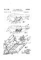
- FIGURE 1 is an isometric view of an amphibious vehicle utilizing the improved closure means to close an opening in the body which receives a retractable wheel of the vehicle.
- FIGURE 2 is a view similar to FIGURE 1, but showing the parts in a different position.
- FIGURE 3 is an enlarged sectional view showing a portion of the interior of the hull of the vehicle in FIG- URE 1, the closure apparatus being in compressed or open position, and a control circuit being shown diagrammatically.
- FIGURE 4 is a view similar to FIGURE 3, but showing the closure apparatus in partially closed position.
- FIGURE 5 is a view similar to FIGURE 3 but showing the closure apparatus in closed position.
- FIGURE 6 is an enlarged detail view of a portion of the apparatus, with parts of the structure being broken away.
- the vehicle body comprises a hull having retractable wheels which move through openings in the hull between expanded or land operating position and retracted or water operating position.
- this invention provides a novel and improved closure apparatus comprising a plurality of elongated, inflatable flexible cells arranged in side by side abutting, fluid tight relationship, and movable between a compressed, deflated position adjacent one side of the opening, and an expanded inflated position wherein the cells close the opening.
- inflated flexible fluid tight air cells provides advantages in that this closure device absorbs the shock of impact loads received from rough water because of the compressibility of the air which inflates the cells. Furthermore, the flexibility of the closure causes heavy impact loads to be transferred to the rigid hull structure without damage to the closure.
- the surface of the closure ap proximates the contour of the hull because of the fact that the closure cells are made of flexible material which is anchored to the hull along opposite ends of'the wheel openings.
- an amphibious vehicle is indicated generally as 10, and has a hull or body 12 formed with an opening '14 through "ice which one of the wheels 16 of the vehiclemay project.
- the vehicle is provided with a plurality of wheels 16, 18 and 2t), and these wheels are movable between the extended or land operating position of FIGURE 1 and the retracted or water operating position of FIGURE 2.
- the opening through which each wheel moves may be closed by apparatus similar to the closure apparatus which is illustrated for the opening 14.
- the closure apparatus comprises a plurality of elon gated inflatable flexible cells designated generally by the reference character 22 and including a leading cell 24, a trailing cell 26 and a plurality of intermediate cells, all of which are interconnected between the leading cell 24 and the trailing cell 26 in abutting fluid tight relationship. As shown in FIGURE 6 at 22a, there are passages between each cell providing for fluid communication therebetween.
- the trailing cell 26 is connected to an air supply pipe 28 which communicates with a source of compressed air 30 so that the cells 22 may selectively be inflated as they appear in FIGURES 2, 5 and 6 or deflated as they appear in FIGURES 1 and 3.
- Means are provided for moving the cells between their compressed deflated position adjacent one side of the opening 14 (FIGURES l and 3) and their expanded inflated position wherein said cells close the opening 14 (FIGURES 2 and 5), and preferably the moving means for the cells is interconnected with the fluid supply means 30 as shown diagrammatically in FIGURE 3 so that the cells are inflated as they are driven toward expanded position and are deflated as they are driven toward compressed position.
- movement of the cells toward expanded position is aided by the force of the compressed air which is used to inflate the air cells.
- FIGURES 3, 4 and 5 there is an air cylinder device designated generally as 32 pivotally mounted at one end on a bracket 34 carried by a support bulkhead 36 inside the hull 12.
- the piston rod 38 of the device 32 is pivotally connected to one link 40 of a pair of toggle links connected between the bulkhead 36 and the leading cell 24 of the closure device.
- One end of the link 49 is pivotally connected to a support bracket 42 on the bulkhead 36, and the other end is pivotally connected to another link 44 which is pivoted on the leading cell 24.
- the link 44 has a free end projecting past the pivotal connection with the link 46, and formed with a stop flange 46 adapted to abut an edge of the link 4! when the closure device is in expanded position to lock the device in this position.
- a spring 48 interconnects the links 40 and 44 to aid the motor means 32 in retracting the closure device.
- At the other end of the opening 14 there is a similar air cylinder motor device and linkage system which need not be described.
- Guide means comprising slotted channels 50 and 52 are mounted to extend along opposite ends of the opening 14, and each channel slidably seats one end of each of the cells 22.
- each of the guide channels has an expanded portion 50a and 52a, respectively, which extend past the edge of the opening 14 to receive the ends of the cells 22 when the closure device is in compressed deflated position, as shown best in FIGURE 3.
- Each channel is also provided with an elongated slot Sill; and 52b, respectively, these slots extending throughout substantially the entire length of the channels.
- Support means comprises flexible cables 54, one of which is connected between each of the cells 22 (see FIGURE 6) andv extends along the length thereof between the channels 50, 52. As shown in the drawings, the cables project through and are slidable along the slots 59b, 52b in the channels, so that the cables help liold the inflated cells in the desired contour and help seal the cells at opposite sides of the opening 14.
- FIGURE 3 shows diagrammatically a control means which is connected with. themotor means 32 and the cells 22 so that the cells are inflatedas they are moved toward expanded position and deflated as they are moved toward compressed position;
- a rotary valve designated generally as 60 having a rotatable body 62 provided with a first fluid passage 64 and a second fluid passage 66.
- the valve has an air supply port 68, an exhaust port 70, an expand port 72 and a retract port 74.
- the air supply port 68 is connected by a pipe 76 to the air supply 30 and the exhaust port is vented to atmosphere through a pipe 78.
- the expand port 72 is connected by a pipe 80 to the pivoted end of the cylinders 32 and also to the air supply pipe 28 for the cells 22.
- the retract port 74 is connected by a pipe 82 to the rod end of the cylinders 32.
- closure apparatus of the character described, including: a plurality of elongated inflatable flexible cells movably mounted on said body and arranged side by side in abutting fluid tight relationship; means for moving said cells between a compressed deflated position adjacent one side of said opening and an expanded inflated position wherein said cells close said opening, comprising a linkage system connected between said body and the leading one of said cells, and motor means for operating said linkage system to drive said cells between compressed 2.
- said flid supply means include control means connected with said motor means and said cells.
- Apparatus of the character claimed in claim 1 including lochng means on said linkage system for locking said cells inexpanded position.
- closure apparatus of the character described, including: a plurality of elongated inflatable flexible cells movably mounted on said body and arranged side by side in abutting 'fiuid tight relationship; means for moving said cells between a compressed deflated position adjacent one side of said opening and an expanded inflated position wherein said cells close said'opening, comprising a linkage system connected between said body and the leading one of said cells and motor means for operating said linkage system to drive said cells between compressed and.
- said linkage system comprises a pair of toggle links which move between a folded position when the cells are compressed and an extended position when the lock saidcells in expanded position.
- closure apparatus comprising, a closure member including a plurality of elongated inflatable cells arranged side-by-side in abutting fluid tight relationship, means mounting said mem ber on said body for movement relative to said opening between a retracted deflated open position wherein said cells are located to one side ofsaid opening and an extended inflated closed position wherein said cells close said opening, means including motor means connected of elongated inflatable cells arranged side-by-side in abuttended inflated closed position wherein said cells close and expanded positions; and fluid supply means for in flating said cells as they are driven toward expanded position and for deflating said cells as they are driven tgward compressed position.
- closure appa ratus of the character described including: a plurality of elongatedinflatable cells movably mounted on said body and arranged side-by-side in abutting fluid tight relationship; means for moving said cells between a retracted deflated position adjacent one side of said opening and an extended inflated position wherein said cells closesaid opening; fluid supply means for inflating said cells as they are moved toward extended position and for deflating said cells as they are moved toward retracted position; and guide means for guiding the movement of said cells between said retracted and extended positions comprising cllarmeis extending long opposite ends of said opening, each channel slidably seating one end of each of said cells.
Landscapes
- Engineering & Computer Science (AREA)
- Chemical & Material Sciences (AREA)
- Combustion & Propulsion (AREA)
- Mechanical Engineering (AREA)
- Ocean & Marine Engineering (AREA)
- Transportation (AREA)
- Invalid Beds And Related Equipment (AREA)
Description
1964 w. A. BOHNER ETAL 3,151,553
INFLATABLE CLOSURE APPARATUS Filed 001:. 27, 1961 2 Sheets-Sheet l INV EN TORS Oct. 6, 1964 w. A. BOHNER ETAL 3,151,563
INFLATABLE CLOSURE APPARATUS Filed Oct. 27, 1961 2 Sheets-Sheet 2 INVENTORS A ORNEY f United States Patent 3,151,663 INFLATABLE CLOSURE APPARATUS Walter A. Bohner, Pontiac, and John S. Edstam, Rochester, Mich, assignors to General Motors Corporation, Detroit, Mich, a corporation of Delaware Filed Oct. 27, 1961, Ser. No. 148,198 9 Claims. (Cl. 169-454) This invention relates to closure apparatus, and more particularly to inflatable closure apparatus for closing an opening in a body.
One feature of the invention is that it provides an improved closure for an opening in a body. Another feature of the invention is that it provides novel closure apparatus for an opening in a body, comprising a plurality of elongated inflatable cells movably mounted on the body and arranged side by side in abutting, fluid tight relationship. A further feature of the invention is that means are provided for moving said cells between a compressed deflated position adjacent an opening in the body and an expanded inflated position wherein said cells close said opening, said cells being inflated as they move toward expanded position and deflated as they move toward compressed position.
Other features and advantages of the invention will be apparent from the following description, having reference to the drawings in which:
FIGURE 1 is an isometric view of an amphibious vehicle utilizing the improved closure means to close an opening in the body which receives a retractable wheel of the vehicle.
FIGURE 2 is a view similar to FIGURE 1, but showing the parts in a different position.
FIGURE 3 is an enlarged sectional view showing a portion of the interior of the hull of the vehicle in FIG- URE 1, the closure apparatus being in compressed or open position, and a control circuit being shown diagrammatically.
FIGURE 4 is a view similar to FIGURE 3, but showing the closure apparatus in partially closed position.
FIGURE 5 is a view similar to FIGURE 3 but showing the closure apparatus in closed position.
FIGURE 6 is an enlarged detail view of a portion of the apparatus, with parts of the structure being broken away.
In an amphibious vehicle which is designed to operate on land and in the water, the vehicle body comprises a hull having retractable wheels which move through openings in the hull between expanded or land operating position and retracted or water operating position. When the wheels are in retracted position it is necessary to close the openings, and this invention provides a novel and improved closure apparatus comprising a plurality of elongated, inflatable flexible cells arranged in side by side abutting, fluid tight relationship, and movable between a compressed, deflated position adjacent one side of the opening, and an expanded inflated position wherein the cells close the opening. The use of inflated flexible fluid tight air cells for this purpose provides advantages in that this closure device absorbs the shock of impact loads received from rough water because of the compressibility of the air which inflates the cells. Furthermore, the flexibility of the closure causes heavy impact loads to be transferred to the rigid hull structure without damage to the closure. The surface of the closure ap proximates the contour of the hull because of the fact that the closure cells are made of flexible material which is anchored to the hull along opposite ends of'the wheel openings.
Referring now more particularly to the drawings, an amphibious vehicle is indicated generally as 10, and has a hull or body 12 formed with an opening '14 through "ice which one of the wheels 16 of the vehiclemay project. As shown in FIGURES 1 and 2, the vehicle is provided with a plurality of wheels 16, 18 and 2t), and these wheels are movable between the extended or land operating position of FIGURE 1 and the retracted or water operating position of FIGURE 2. The opening through which each wheel moves may be closed by apparatus similar to the closure apparatus which is illustrated for the opening 14.
The closure apparatus comprises a plurality of elon gated inflatable flexible cells designated generally by the reference character 22 and including a leading cell 24, a trailing cell 26 and a plurality of intermediate cells, all of which are interconnected between the leading cell 24 and the trailing cell 26 in abutting fluid tight relationship. As shown in FIGURE 6 at 22a, there are passages between each cell providing for fluid communication therebetween. The trailing cell 26 is connected to an air supply pipe 28 which communicates with a source of compressed air 30 so that the cells 22 may selectively be inflated as they appear in FIGURES 2, 5 and 6 or deflated as they appear in FIGURES 1 and 3.
Means are provided for moving the cells between their compressed deflated position adjacent one side of the opening 14 (FIGURES l and 3) and their expanded inflated position wherein said cells close the opening 14 (FIGURES 2 and 5), and preferably the moving means for the cells is interconnected with the fluid supply means 30 as shown diagrammatically in FIGURE 3 so that the cells are inflated as they are driven toward expanded position and are deflated as they are driven toward compressed position. By this means movement of the cells toward expanded position is aided by the force of the compressed air which is used to inflate the air cells.
As shown in FIGURES 3, 4 and 5, there is an air cylinder device designated generally as 32 pivotally mounted at one end on a bracket 34 carried by a support bulkhead 36 inside the hull 12. The piston rod 38 of the device 32 is pivotally connected to one link 40 of a pair of toggle links connected between the bulkhead 36 and the leading cell 24 of the closure device. One end of the link 49 is pivotally connected to a support bracket 42 on the bulkhead 36, and the other end is pivotally connected to another link 44 which is pivoted on the leading cell 24. The link 44 has a free end projecting past the pivotal connection with the link 46, and formed with a stop flange 46 adapted to abut an edge of the link 4!) when the closure device is in expanded position to lock the device in this position. A spring 48 interconnects the links 40 and 44 to aid the motor means 32 in retracting the closure device. At the other end of the opening 14 there is a similar air cylinder motor device and linkage system which need not be described.
Guide means comprising slotted channels 50 and 52 are mounted to extend along opposite ends of the opening 14, and each channel slidably seats one end of each of the cells 22. As shown in FIGURES 3, 4 and 5, each of the guide channels has an expanded portion 50a and 52a, respectively, which extend past the edge of the opening 14 to receive the ends of the cells 22 when the closure device is in compressed deflated position, as shown best in FIGURE 3. Each channel is also provided with an elongated slot Sill; and 52b, respectively, these slots extending throughout substantially the entire length of the channels.
Support means comprises flexible cables 54, one of which is connected between each of the cells 22 (see FIGURE 6) andv extends along the length thereof between the channels 50, 52. As shown in the drawings, the cables project through and are slidable along the slots 59b, 52b in the channels, so that the cables help liold the inflated cells in the desired contour and help seal the cells at opposite sides of the opening 14.
' FIGURE 3 shows diagrammatically a control means which is connected with. themotor means 32 and the cells 22 so that the cells are inflatedas they are moved toward expanded position and deflated as they are moved toward compressed position; In FIGURE 3 there is a rotary valve designated generally as 60 having a rotatable body 62 provided with a first fluid passage 64 and a second fluid passage 66. The valve has an air supply port 68, an exhaust port 70, an expand port 72 and a retract port 74. The air supply port 68 is connected by a pipe 76 to the air supply 30 and the exhaust port is vented to atmosphere through a pipe 78. The expand port 72 is connected by a pipe 80 to the pivoted end of the cylinders 32 and also to the air supply pipe 28 for the cells 22. The retract port 74 is connected by a pipe 82 to the rod end of the cylinders 32. a
' In the operation of the closure apparatus, if it is desired to change the condition of the vehicle from the land operating condition of FIGURES l and 3 to the water operating condition of FIGURES 2 and 5, the vehicle wheels are retracted and then the openings through which the wheels move are closed. In order to close the opening 14 the power cylinders 32 are actuated to extend the piston rods 38, unfolding the toggle links 40,
44, and driving the array of cells 22 from the position of. FIGURE 3 toward the position of FIGURE 5. At the same time, air underpressure is admitted to thepipe 28 to inflate the cells which are connected together by air passages 22a in a conventional manner similar to that of air mattresses. The force of the inflating air aids in the movement of the cells from the compressed deflated position of FIGURES 1 and 3 to the expanded inflated position of FIGURES 2 and 5. This operation is accomplished by placing the valve 60 in the condition shown in FIGURE 3, wherein the valve passage 64 connects the fluid supply port 68 with the expand port 72 and the valve passage 66 connects the retract port 74 to the exhaust port 70. When the array of cells approaches the fully expanded position of FIGURE the point of pivotal interconnection of the toggle links 40, 44 passes over center and the stop flange 46 abuts the upper surface of the link 40 to provide a stop. The over center arrangement locks the cells in fully expanded position. When it is desired to convert the vehicle from water operation to land operation the procedure above described is reversed, and the valve passage 66 is connected between ports 68 and 74 while the passage 64 is connectedbetween ports 72 and 70. The power cylinder 32 is driven in a reverse direction to retract the piston rod 38 and simultaneously the pipe 28 is opened to atmosphere so that air may be exhausted from the cells 22 as they move toward their compressed deflated position.
While we have shown and described one embodiment of our invention, it is capable of many modifications. Changes, therefore, in the construction and arrangement may be made without departing from the spirit and scope of the invention as set forth in the appended claims.
We claim: t p
'1. In a vehicle body having an opening therein, closure apparatus of the character described, including: a plurality of elongated inflatable flexible cells movably mounted on said body and arranged side by side in abutting fluid tight relationship; means for moving said cells between a compressed deflated position adjacent one side of said opening and an expanded inflated position wherein said cells close said opening, comprising a linkage system connected between said body and the leading one of said cells, and motor means for operating said linkage system to drive said cells between compressed 2. Apparatus of the characted claimed inclaim' 1, v
wherein said flid supply means include control means connected with said motor means and said cells.
3. Apparatus of the character claimed in claim 1, including lochng means on said linkage system for locking said cells inexpanded position.
4. In a vehicle body having an opening therein, closure apparatus of the character described, including: a plurality of elongated inflatable flexible cells movably mounted on said body and arranged side by side in abutting 'fiuid tight relationship; means for moving said cells between a compressed deflated position adjacent one side of said opening and an expanded inflated position wherein said cells close said'opening, comprising a linkage system connected between said body and the leading one of said cells and motor means for operating said linkage system to drive said cells between compressed and.
7 expanded positions; means for locking said cells in excells are expanded, said links passing over center to panded position; fluid supply means for inflating said cells as they are driven toward expanded position and for deflating said cells as they are driven toward com pressed position; guide means comprising slotted channels extending along opposite ends of said opening, each channel slidably seating one end of each of said cells; and support means comprising a flexible cable connected to each of said cells and extending along the length thereof between said channels, said cables projecting through and being slidable along the slot in each of said channels.
5. Apparatus of the character claimed in claim 4, wherein said linkage system comprises a pair of toggle links which move between a folded position when the cells are compressed and an extended position when the lock saidcells in expanded position.
' 6. In a body having an opening therein, closure apparatus comprising, a closure member including a plurality of elongated inflatable cells arranged side-by-side in abutting fluid tight relationship, means mounting said mem ber on said body for movement relative to said opening between a retracted deflated open position wherein said cells are located to one side ofsaid opening and an extended inflated closed position wherein said cells close said opening, means including motor means connected of elongated inflatable cells arranged side-by-side in abuttended inflated closed position wherein said cells close and expanded positions; and fluid supply means for in flating said cells as they are driven toward expanded position and for deflating said cells as they are driven tgward compressed position.
said opening, means for moving said closure member laterally to the direction of the elongation of said cells between said open and closed positions thereof, fluid supply means for selectively inflating said cells as said member is moved toward said closed position and for deflating said cells as said closure member is moved toward said open position, and guide means for guiding the movement of said closure member between said open and closed positions thereof. a
a 8. In a body having an opening therein, closure appa ratus of the character described, including: a plurality of elongatedinflatable cells movably mounted on said body and arranged side-by-side in abutting fluid tight relationship; means for moving said cells between a retracted deflated position adjacent one side of said opening and an extended inflated position wherein said cells closesaid opening; fluid supply means for inflating said cells as they are moved toward extended position and for deflating said cells as they are moved toward retracted position; and guide means for guiding the movement of said cells between said retracted and extended positions comprising cllarmeis extending long opposite ends of said opening, each channel slidably seating one end of each of said cells.
9. Apparatus of the character claimed in claim 8, wherein said guide channels are slotted and wherein there are support means comprising a flexible member connected to each of said cells extending along the length thereof between said channels, said flexible members projecting through and i said channels.
References Cited in the file of this patent UNlT ED STATES PATENTS 1,221,496 Wullyamoz et a1 Apr. 3, 1917 1,806,859 Mattel May 26, 1931 1,976,793 Marigold Oct. 16, 1934 2,747,929 Masano May 29, 1956 2,867,499 Duddleston Sept. 24, 1957 2,977,166 Dull Mar. 28, 1961 oerng sliaole in the slot in each of
Claims (1)
- 6. IN A BODY HAVING AN OPENING THEREIN, CLOSURE APPARATUS COMPRISING, A CLOSURE MEMBER INCLUDING A PLURALITY OF ELONGATED INFLATABLE CELLS ARRANGED SIDE-BY-SIDE IN ABUTTING FLUID TIGHT RELATIONSHIP, MEANS MOUNTING SAID MEMBER ON SAID BODY FOR MOVEMENT RELATIVE TO SAID OPENING BETWEEN A RETRACTED DEFLATED OPEN POSITION WHEREIN SAID CELLS ARE LOCATED TO ONE SIDE OF SAID OPENING AND AN EXTENDED INFLATED CLOSED POSITION WHEREIN SAID CELLS CLOSE SAID OPENING, MEANS INCLUDING MOTOR MEANS CONNECTED TO AT LEAST ONE OF SAID CELLS FOR MOVING SAID MEMBER BETWEEN SAID OPEN AND CLOSED POSITIONS THEREOF, AND FLUID SUPPLY MEANS FOR SELECTIVELY INFLATING SAID CELLS AS SAID
Priority Applications (1)
| Application Number | Priority Date | Filing Date | Title |
|---|---|---|---|
| US148108A US3151663A (en) | 1961-10-27 | 1961-10-27 | Inflatable closure apparatus |
Applications Claiming Priority (1)
| Application Number | Priority Date | Filing Date | Title |
|---|---|---|---|
| US148108A US3151663A (en) | 1961-10-27 | 1961-10-27 | Inflatable closure apparatus |
Publications (1)
| Publication Number | Publication Date |
|---|---|
| US3151663A true US3151663A (en) | 1964-10-06 |
Family
ID=22524313
Family Applications (1)
| Application Number | Title | Priority Date | Filing Date |
|---|---|---|---|
| US148108A Expired - Lifetime US3151663A (en) | 1961-10-27 | 1961-10-27 | Inflatable closure apparatus |
Country Status (1)
| Country | Link |
|---|---|
| US (1) | US3151663A (en) |
Cited By (20)
| Publication number | Priority date | Publication date | Assignee | Title |
|---|---|---|---|---|
| US3226152A (en) * | 1963-07-31 | 1965-12-28 | Gen Motors Corp | Fluid-actuated visor systems |
| US3231006A (en) * | 1962-06-14 | 1966-01-25 | Du Pont | Pneumatically-actuated roll-up closure |
| US3280785A (en) * | 1965-03-01 | 1966-10-25 | George H Mycroft | Amphibious structure |
| US3599702A (en) * | 1969-07-10 | 1971-08-17 | Norman M Bedard | Pneumatically operated collapsible unit |
| US3753317A (en) * | 1970-05-13 | 1973-08-21 | Gen Automatisme Co | Inflatable pocket arrangement for selectively closing a passageway |
| US3854253A (en) * | 1972-05-01 | 1974-12-17 | J Slowbe | Joint construction between supported and supporting members |
| US3903831A (en) * | 1973-05-14 | 1975-09-09 | Waterland Corp | Amphibious vehicle |
| US4038788A (en) * | 1973-01-16 | 1977-08-02 | Willem Maria August Claessens | Sliding roof |
| US4581860A (en) * | 1985-06-20 | 1986-04-15 | Berger Horst L | Saddle-shaped cable dome system for large span lightweight roof structures |
| US4672888A (en) * | 1985-01-03 | 1987-06-16 | Insul-Rib, Inc. | Inflatable greenhouse vent cover |
| WO1995012736A1 (en) * | 1993-11-02 | 1995-05-11 | Hisami Nogaki | Operator for a sliding overhead door |
| US5450807A (en) * | 1994-09-12 | 1995-09-19 | The United States Of America As Represented By The Secretary Of The Navy | Shutter door assembly |
| US20060003687A1 (en) * | 2003-06-12 | 2006-01-05 | Jean-Guy Dube | Ventilation barrier |
| US20060000407A1 (en) * | 2004-07-01 | 2006-01-05 | Deane Henderson | Under-gunnel locker door |
| KR20160026139A (en) * | 2014-08-29 | 2016-03-09 | 삼성중공업 주식회사 | Offshore structure having the watertight compartment |
| US20160318377A1 (en) * | 2013-06-11 | 2016-11-03 | Aymeric PATIN | Device for blacking-out a picture window actuated by an inflatable element |
| WO2017076637A1 (en) * | 2015-11-02 | 2017-05-11 | Skf Marine Gmbh | Cover device and thruster |
| US20190195011A1 (en) * | 2017-12-21 | 2019-06-27 | Ilc Dover Ip, Inc. | Flexible covering for door and window openings |
| US10988220B2 (en) | 2017-05-02 | 2021-04-27 | Skf Marine Gmbh | Cover device and thruster |
| US11648827B2 (en) * | 2019-12-10 | 2023-05-16 | GM Global Technology Operations LLC | Pneumatic shade |
Citations (6)
| Publication number | Priority date | Publication date | Assignee | Title |
|---|---|---|---|---|
| US1221496A (en) * | 1916-09-19 | 1917-04-03 | Frederic Wullyamoz | Leak-obturating device for ships. |
| US1806859A (en) * | 1928-12-24 | 1931-05-26 | mattei | |
| US1976793A (en) * | 1930-08-14 | 1934-10-16 | Mangold Stefan | Air-tight closed hollow body |
| US2747929A (en) * | 1953-05-04 | 1956-05-29 | Masano Thomas | Pneumatic convertible top for automobiles |
| US2807499A (en) * | 1955-04-29 | 1957-09-24 | Kenneth J Duddleston | Compress air spreader for a vehicle tarpaulin cover |
| US2977106A (en) * | 1957-05-08 | 1961-03-28 | Selas Corp Of America | Furnace closure |
-
1961
- 1961-10-27 US US148108A patent/US3151663A/en not_active Expired - Lifetime
Patent Citations (6)
| Publication number | Priority date | Publication date | Assignee | Title |
|---|---|---|---|---|
| US1221496A (en) * | 1916-09-19 | 1917-04-03 | Frederic Wullyamoz | Leak-obturating device for ships. |
| US1806859A (en) * | 1928-12-24 | 1931-05-26 | mattei | |
| US1976793A (en) * | 1930-08-14 | 1934-10-16 | Mangold Stefan | Air-tight closed hollow body |
| US2747929A (en) * | 1953-05-04 | 1956-05-29 | Masano Thomas | Pneumatic convertible top for automobiles |
| US2807499A (en) * | 1955-04-29 | 1957-09-24 | Kenneth J Duddleston | Compress air spreader for a vehicle tarpaulin cover |
| US2977106A (en) * | 1957-05-08 | 1961-03-28 | Selas Corp Of America | Furnace closure |
Cited By (26)
| Publication number | Priority date | Publication date | Assignee | Title |
|---|---|---|---|---|
| US3231006A (en) * | 1962-06-14 | 1966-01-25 | Du Pont | Pneumatically-actuated roll-up closure |
| US3226152A (en) * | 1963-07-31 | 1965-12-28 | Gen Motors Corp | Fluid-actuated visor systems |
| US3280785A (en) * | 1965-03-01 | 1966-10-25 | George H Mycroft | Amphibious structure |
| US3599702A (en) * | 1969-07-10 | 1971-08-17 | Norman M Bedard | Pneumatically operated collapsible unit |
| US3753317A (en) * | 1970-05-13 | 1973-08-21 | Gen Automatisme Co | Inflatable pocket arrangement for selectively closing a passageway |
| US3854253A (en) * | 1972-05-01 | 1974-12-17 | J Slowbe | Joint construction between supported and supporting members |
| US4038788A (en) * | 1973-01-16 | 1977-08-02 | Willem Maria August Claessens | Sliding roof |
| US3903831A (en) * | 1973-05-14 | 1975-09-09 | Waterland Corp | Amphibious vehicle |
| US4672888A (en) * | 1985-01-03 | 1987-06-16 | Insul-Rib, Inc. | Inflatable greenhouse vent cover |
| US4581860A (en) * | 1985-06-20 | 1986-04-15 | Berger Horst L | Saddle-shaped cable dome system for large span lightweight roof structures |
| WO1995012736A1 (en) * | 1993-11-02 | 1995-05-11 | Hisami Nogaki | Operator for a sliding overhead door |
| US5429170A (en) * | 1993-11-02 | 1995-07-04 | Nogaki; Hisami | Operator for a sliding overhead door |
| US5450807A (en) * | 1994-09-12 | 1995-09-19 | The United States Of America As Represented By The Secretary Of The Navy | Shutter door assembly |
| US20060003687A1 (en) * | 2003-06-12 | 2006-01-05 | Jean-Guy Dube | Ventilation barrier |
| US7357710B2 (en) * | 2003-06-12 | 2008-04-15 | Guy St-Jean | Ventilation barrier |
| US20060000407A1 (en) * | 2004-07-01 | 2006-01-05 | Deane Henderson | Under-gunnel locker door |
| US20160318377A1 (en) * | 2013-06-11 | 2016-11-03 | Aymeric PATIN | Device for blacking-out a picture window actuated by an inflatable element |
| KR20160026139A (en) * | 2014-08-29 | 2016-03-09 | 삼성중공업 주식회사 | Offshore structure having the watertight compartment |
| KR101711514B1 (en) | 2014-08-29 | 2017-03-02 | 삼성중공업 주식회사 | Offshore structure having the watertight compartment |
| WO2017076637A1 (en) * | 2015-11-02 | 2017-05-11 | Skf Marine Gmbh | Cover device and thruster |
| JP2018531841A (en) * | 2015-11-02 | 2018-11-01 | エス・ケイ・エフ マリーン ゲゼルシャフト ミット ベシュレンクテル ハフツングSKF Marine GmbH | Cover device and thruster |
| US10421522B2 (en) * | 2015-11-02 | 2019-09-24 | Skf Marine Gmbh | Cover device and thruster |
| US10988220B2 (en) | 2017-05-02 | 2021-04-27 | Skf Marine Gmbh | Cover device and thruster |
| US20190195011A1 (en) * | 2017-12-21 | 2019-06-27 | Ilc Dover Ip, Inc. | Flexible covering for door and window openings |
| US10648227B2 (en) * | 2017-12-21 | 2020-05-12 | Ilc Dover Ip, Inc. | Flexible covering for door and window openings |
| US11648827B2 (en) * | 2019-12-10 | 2023-05-16 | GM Global Technology Operations LLC | Pneumatic shade |
Similar Documents
| Publication | Publication Date | Title |
|---|---|---|
| US3151663A (en) | Inflatable closure apparatus | |
| US2704225A (en) | Convertible automobile top | |
| US4784429A (en) | Collapsible camper top for pick-up trucks | |
| US3506222A (en) | Aircraft supporting device | |
| US3004737A (en) | Retractable buoyant supporting means for vehicles | |
| CN106715189A (en) | Electric vehicle | |
| US3943869A (en) | Submarine boat | |
| US3727716A (en) | Air cushion trunk for ground effect machines | |
| US2463351A (en) | Aircraft and undercarriage therefor | |
| US4004761A (en) | Outrigger air cushion landing system | |
| US4032088A (en) | Outrigger air bag landing system | |
| NO165105B (en) | ANALOGUE PROCEDURE FOR THE PREPARATION OF THERAPEUTIC ACTIVE 1-CYCLOPROPYL-6-FLUOR-1,4-DIHYDRO-4-OXO-7- (1-PIPERAZINYL) -3-QUINOLINE CARBOXYL ACIDS. | |
| US2850747A (en) | Amphibious catamaran | |
| US3301343A (en) | Inflatable buoyancy chambers with vehicles equipped therewith | |
| CN102490895B (en) | Folding inflatable buoy and seaplane using the foldable inflatable buoy | |
| US4328601A (en) | Inflatable bow | |
| US3330240A (en) | Ground effect vehicle | |
| US3379270A (en) | Vessel convertible to watercraft and air cushion vehicle | |
| US3102705A (en) | Flotation device | |
| US4802433A (en) | Amphibious vehicle | |
| EP0076811B1 (en) | Variable air cushion mode vehicle | |
| US3256539A (en) | Variable buoyancy float | |
| US3321158A (en) | Retractile and collapsible floats for aircraft | |
| US3273832A (en) | Inflatable pontoon for aircraft | |
| GB1069194A (en) | Improvements in or relating to gaseous cushion supported vehicles |