US3145544A - Refrigeration system impurity purge means - Google Patents
Refrigeration system impurity purge means Download PDFInfo
- Publication number
- US3145544A US3145544A US150802A US15080261A US3145544A US 3145544 A US3145544 A US 3145544A US 150802 A US150802 A US 150802A US 15080261 A US15080261 A US 15080261A US 3145544 A US3145544 A US 3145544A
- Authority
- US
- United States
- Prior art keywords
- refrigerant
- liquid
- shell
- outlet
- pressure
- Prior art date
- Legal status (The legal status is an assumption and is not a legal conclusion. Google has not performed a legal analysis and makes no representation as to the accuracy of the status listed.)
- Expired - Lifetime
Links
- 238000010926 purge Methods 0.000 title claims description 51
- 238000005057 refrigeration Methods 0.000 title claims description 29
- 239000012535 impurity Substances 0.000 title description 21
- 239000003507 refrigerant Substances 0.000 claims description 92
- 239000007789 gas Substances 0.000 claims description 65
- XLYOFNOQVPJJNP-UHFFFAOYSA-N water Substances O XLYOFNOQVPJJNP-UHFFFAOYSA-N 0.000 claims description 17
- 239000007788 liquid Substances 0.000 description 69
- 230000007246 mechanism Effects 0.000 description 21
- 238000007599 discharging Methods 0.000 description 18
- 239000002826 coolant Substances 0.000 description 6
- 239000012530 fluid Substances 0.000 description 5
- 230000004048 modification Effects 0.000 description 4
- 238000012986 modification Methods 0.000 description 4
- 230000009471 action Effects 0.000 description 3
- 238000005192 partition Methods 0.000 description 3
- 238000005086 pumping Methods 0.000 description 3
- 230000035508 accumulation Effects 0.000 description 2
- 238000009825 accumulation Methods 0.000 description 2
- 238000009833 condensation Methods 0.000 description 2
- 230000005494 condensation Effects 0.000 description 2
- 238000010276 construction Methods 0.000 description 2
- 230000000630 rising effect Effects 0.000 description 2
- 238000000926 separation method Methods 0.000 description 2
- 230000008859 change Effects 0.000 description 1
- 230000000694 effects Effects 0.000 description 1
- 230000005484 gravity Effects 0.000 description 1
- 230000000737 periodic effect Effects 0.000 description 1
- 238000005201 scrubbing Methods 0.000 description 1
Images

Classifications
-
- F—MECHANICAL ENGINEERING; LIGHTING; HEATING; WEAPONS; BLASTING
- F25—REFRIGERATION OR COOLING; COMBINED HEATING AND REFRIGERATION SYSTEMS; HEAT PUMP SYSTEMS; MANUFACTURE OR STORAGE OF ICE; LIQUEFACTION SOLIDIFICATION OF GASES
- F25B—REFRIGERATION MACHINES, PLANTS OR SYSTEMS; COMBINED HEATING AND REFRIGERATION SYSTEMS; HEAT PUMP SYSTEMS
- F25B43/00—Arrangements for separating or purifying gases or liquids; Arrangements for vaporising the residuum of liquid refrigerant, e.g. by heat
- F25B43/04—Arrangements for separating or purifying gases or liquids; Arrangements for vaporising the residuum of liquid refrigerant, e.g. by heat for withdrawing non-condensible gases
- F25B43/043—Arrangements for separating or purifying gases or liquids; Arrangements for vaporising the residuum of liquid refrigerant, e.g. by heat for withdrawing non-condensible gases for compression type systems
Definitions
- One object of the invention is to provide a refrigeration system purging apparatus which operates automatically without attention by the operator.
- a further object of the invention is to provide a refrigeration system purge apparatus when can be operated when the refrigeration system is not running.
- a still further object of the invention is to provide a refrigeration system purge apparatus which removes both liquid and gaseous impurities.
- Another object of the invention is to provide a refrigeration system purge apparatus which can be utilized in various different systems without change, modification or redesign of the system.
- An additional object is to provide a purge apparatus which can be used on sub-atmospheric refrigeration systerns.
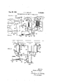
- FIGURE 1 is a diagrammatic view of a refrigeration system having one embodiment of the invention incorp rated therein;
- FIG. 2 is a fragmentary diagrammatic view illustrating a modification of the FIG. 1 embodiment
- FIG. 3 is another fragmentary diagrammatic view illustrating a further modification of the FIG. 1 embodiment
- FIG. 4 is a fragmentary diagrammatic view illustrating an arrangement which incorporates features of the FIG. 2 and FIG. 3 embodiment;
- FIG. 5 is a diagrammatic view of a refrigeration system having a further embodiment of the invention incorporated therewith.
- FIG. 6 is a fragmentary diagrammatic view of a modified form of the invention embodiment shown in FIG. 5.
- FIG. 1 there is shown therein a mechanical refrigeration system including a refrigerant compressor 10, a high pressure gaseous refrigerant line 12, a refrigerant condenser 14 of the tube-shell type, a conventional refrigerant-restricting float valve means 16, a liquid refrigerant line 18, a refrigerant evaporator 20 of the tube-shell type, and a low pressure or suction line 22.
- the refrigeration system as above described is a conventional system usually constructed in capacities upwards of fifty tons, and the invention is concerned therewith only to the extent that a novel refrigerant impurity-removing mechanism is utilized therewith.
- the impurity-removing apparatus includes an upright heat exchange shell or chamber means 24 connected to condenser 14 by means of a small refrig erant line 26.
- a fixed or variable orifice restriction means 28 is preferably provided in line 26 so that the pressure of the refrigerant in shell 24 is somewhat less than condenser pressure.
- a finned heat exchange coil 30 positioned in such a way that the coil surface completely occupies the effective shell cross section and is disposed along the length of the shell.
- the fins 32 of coil 30 fit tightly between a core 34 andthe inner surface of shell 24 so that upwardly flowing fluid must traverse the fin surfaces before reaching outlet conduit 36.
- Heat exchange coil 30 receives its supply of liquid refrigerant from a refrigerant line 38 which connects with the high side of float valve 16. After flowing through coil 30 the refrigerant is returned to the system via a line 40. Line 40 preferably discharges into the system evaporator above its normal liquid level 41 to minimize back pressure effects. During purging operations the temperature of coil 30 is appreciably below the condensing temperature in condenser 14. Thus, refrigerant in purge condenser shell 24 condenses, lowering its pressure and drawing refrigerant vapor and non-condensable gases from condenser 14.
- This flow of vapor through restriction 28 maintains the ressure in purge condenser shell 24 below the pressure in condenser 14 as long as condensing continues in the purge condenser.
- the size and temperature of coil 30 determine the rate of condensation and thereby the rate of flow through restriction 28. Since refrigerant vapor enters the bottom of purge condenser 24 the flow of vapor within the purge condenser is from bottom-to-top. Because of this and the fact that the non-condensable gases are lighter than the refrigerant vapor, the non-condensables accumulate in the top of the purge condenser 24.
- a solenoid valve 44 is located in line 36 which extends from the top of purge condenser 24. p The valve is normally closed for trapping the non-condensables and allowing .them to accumulate in the top of purge condenser 24.
- a pressure switch 50 is connected to the purge condenser 24 and is responsive to the pressure therein such that when the pressure on rising due to the accumulation of non-condensables reaches a preset value, the switch 50 operates to open solenoid valve 44 for releasing the accumulated non-condensable gases to the atmosphere. As soon as the pressure in purge condenser 24 drops to another preset value, usually slightly below the preset pressure at which the switch closes, the switch 50 contacts open to close solenoid valve 44.
- a liquid line 52 which empties into the upper portion of a liquid impurity-separating tank 54 having a pair of vertical par- 'tition's 56 and 58'for defining a first chamber 60 and a "second chamber '62.
- a standpipe 64 is located within chamber 60, with the upper end thereof located slightly above the upper edge of partition 58.
- FIG. 2 there is shown a purge mechanism which in many respects is similar to that employed in theFIG. l arrangement, the only essential difference being "that'in the FIG. 2 arrangement line 36 is provided with 'an electrically driven fluid pump 73.
- This enables the purge mechanism to be utilized with refrigeration systems which operate at sub-atmospheric pressures. It will be seen that during operation both the pump and normally closed solenoid valve 44 are under the control of pressure switch 50; as a result, when the absolute pressure 'in the upper portion of shell 24 reaches a predetermined value as sensed by switch the pump becomes effective to exhaust the non-condensables from the shell. When the pressure drops, valve 44 closes against further escape of the gas.
- FIG. 3 there is shown a purge mechanism which provides for automatic exhaustion of liquid impurities from standpipe 64.
- the mechanism is equipped with a liquid collection chamber "3% having connection with a gas line 82. and a liquid standpip'e line 64a.
- a conventional fioat valve 84 is provided between pipe 64 and line 64a to permit liquid flow from tarik'54'to chamber 89 but to prevent reverse fiow from chamber'Stl to the'tank.
- the discharge line 86 for chamber8tl is provided with a solenoid valve 44a suitably controlled by pressure switch 50.
- FIG. 4 there is shown a purge mechanism which includes the sub-atmospheric feature of the FIG. 2 mechanism and the automatic water exhaustion feature .of the FIG. 3 mechanism.
- the operation of the FIG. 4 mechanism is believed apparent without further description.
- FIG. 5 includes two non-condens able purge mechanisms, one of which may operate when the refrigerant system is running, and the other of which may operate when the refrigerant system is idle. This other standby purge mechanism would in most cases be utilized preparatory to the system being put into use after extended periods of idleness.
- the standby purge mechanism comprises an upright shell 124 having a central core 134 and a finned heat exchange coil 130 snugly disposed in the annular space between the core and the shell inner surface.
- the inlet and outlet tubes 132 and 136 for the coil may be connected to a conventional valved cold watersystem (not shown) for its supply of heat exchange fluid.
- Shell124 may be supplied with system refrigerant via a 78 and line 125.
- solenoid valve 44 In order for line 36 to receive a supply of refrigerant solenoid valve 44 must be open; accordingly there is preferably provided a manual switch 127 for holding valve 44 open during the time the standby unit is operating.
- the motive power for flowing the refrigerant through line 36 is supplied by pump 7 8
- Shell 124 returns refrigerant to the system via a conduit defined by line 129 and the lower portion of line 52.
- manual valves 131 and 133 are closed, manual valve 135 is open, and the system compressor ill is of course idle, with no refrigerant flow through the coil in shell 24.
- the general operation involves a flow of gaseous refrigerant from line 26, upwardly through the inactive shell 24, line '36, pump '78, line and into shell 124.
- the pressure of non-condensables builds in the upper portion of shell "124, while the refrigerant is being condensed by the cold 24 becomes effective to accumulate non-condensables and periodically discharge same through manual valve 133, which is as stated open.
- Tank'54 serves-to remove water from the refrigerant both during standby operation and during normal running of the system.
- FIG. 5 The design of the FIG. 5 system permits operation of both purging units during normal running of the system if desired.
- valve 133 can be closed and valves 131 and 135 opened during normal run operations.
- the flow of cold water through coil produces the final separation of refrigerant anclnoncondensables
- the flow of system refrigerant through coil 39 (in shell 24) produces a preliminary separation of refrigerant from the non-condensables.
- Pump 78 would preferably be placed under the control of pressure switch 59, as in the arrangement of FIGS. 2 and 4. Inclusion of pump 78 permits the FIG. 5 mechanism to be used on sub-atmospheric refrigerating systems.
- FIG. 6 there is shown a purge mechanism which provides the standby feature of the FIG. 5 mechanism and the automatic Water exhaustion feature of the FIG. 3 and 4 mechanisms.
- refrigerant from line 26 flows upwardly through inactive shell 24, solenoid valve 44, purnp'78, line 82, branch line 1125, gas purge shell 124, line 129, the lower portion of line 52, and into water separator tank 54.
- switch 127 is closed, manual valves 131 and '152 are closed, and manual valves 154 and are open. Power for flowing the refrigerant is provided by pump '78.
- FIG. 6 mechanism includes a pump 78, and it therefore can be utilized with sub-atmospheric systems.
- FIG. 6 The design of the FIG. 6 system permits operation of both purging units during normal run periods if detank 54 and shells 24 and 124 relative to the sizes of the system condenser and evaporator are exaggerated, and that in the actual physical form the system devices 14 and 20 would be many times larger than the purge de vices.
- the invention is recognized to be capable of some modification from the various forms thereof shown in the drawings without departing from the spirit of the invention as setrforth in the accompanying claims.
- a mechanical refrigeration system means connected with said system for purging same of non-condensable gases; means connected with said system for separating water from the system refrigerant; means for directing high pressure non-condensable gas accumulations against the separated water to expel same from the water separator means without exposing the refrigeration system to the atmosphere; and an electrically-operated means controlled by the pressure of the non-condensable gases to control the expelling operation.
- a mechanical refrigeration system including a refrigerant compressor, condenser and evaporator; means for purging said system of non-condensable gases including a heat exchange unit having an inlet to receive gaseous refrigerant from the system, having a first outlet for discharging condensed refrigerant therethrough, and having a second outlet for discharging non-condensable gases; means for circulating coolant through said heat exchange unit to condense refrigerant flowing from the aforementioned inlet so that non-condensable gases collect in the heat exchange unit adjacent the second outlet; means for separating foreign liquid impurities from the refrigerant which is discharged from the first outlet; and means for intermittently expelling the separated foreign liquid impurities and non-condensable gases without exposing the refrigeration system to the atmosphere, including a chamber connected with the aforementioned second outlet and foreign liquid separating means, an electrically-operated means for controlling fluid flow from the chamber, and switch means operated by gas pressure in the heat exchange unit for controlling the
- a mechanical refrigeration system including a refrigerant compressor, condenser, evaporator shell having a normal liquid level therein, and float valve between the condenser and evaporator shell; means for purging said system of non-condensable gases including an upright heat exchange unit having an inlet in its lower portion to receive gaseous refrigerant from the system, having a first outlet in its lower portion for discharging condensed refrigerant, and having a second outlet in its upper portion for discharging non-condensable gases; means for circulating coolant through said heat exchange unit to condense refrigerant flowing upwardly from the aforementioned inlet so that non-condensable gases collect in the upper portion of the heat exchange unit adjacent the second outlet; said coolant circulating means comprising a refrigerant evaporator section disposed in the heat exchange unit, a liquid refrigerant line extending from a point located in the system between the condenser and float valve to the inlet of the evapor
- a mechanical refrigeration system including a refrigerant compressor, condenser and evaporator; means for purging said system of non-condensable gases when the system is running, including a first heat exchanger having an inlet to receive gaseous refrigerant from the system, a liquid outlet for discharging condensed refrigerant, and a gas outlet for discharging non-condensable gases; means for circulating system refrigerant in heat transfer relation with said heat exchanger to condense refrigerant flowing from the aforementioned inlet so that non-condensable gases collect adjacent the gas outlet; means for separating foreign liquid from the refrigerant, including a separator chamber for receiving refrigerant and liquid impurity from the liquid outlet, and means operative to skim off a layer of liquid impurity from the chamber refrigerant; means for purging the system of non-condensable gases when the system is idle, including a second heat exchanger having an inlet to receive gaseous refrigerant from the
- means for purging said system of non-condensable gases when the system is running including a first heat exchanger having an inlet to receive gaseous refrigerant from the system, a first liquid outlet for discharging condensed refrigerant, and a first gas outlet for discharging non-condensables; means for circulating system refrigerant through said heat exchanger to condense refrigerant flowing from the aforementioned inlet so that non-condensables collect adjacent the gas outlet; means for separating foreign liquid from the refrigerant, including a separator chamber for receiving refrigerant and liquid impurity from the aforementioned liquid outlet, and means operative to remove a layer of liquid impurity from the chamber refrigerant; means for purging the system of non-condensables when the system is idle, including a second heat exchanger having an inlet to receive gaseous refrigerant
- a mechanical refrigeration system means connected with said system for purging same of non-condensable gases; means connected with said system for separating liquid impurities therefrom; means for causing the purged non-condensable gases to automatically expel separated liquid impurities without excomprising a collection chamber having a first inlet arranged to accept purged non-condensable gases from the purging means, having a second inlet arranged to accept separated liquid impurities from the liquid impurity sepa- .rating means, and having an outlet arranged to exhaust j gas and liquid to the atmosphere; and means between the liquid impurity separating means and said second inlet for permitting liquid to flow into the collection chamber but preventing reverse flow from the collection chamber back to the liquid impurity separating means.
- means for purging said system of non-condensable gases including a first heat exchanger having a first inlet .to receive gaseous refrigerant and non-condensables from the system, a first liquid outlet for discharging condensed refrigerant, and a first gas outlet remote from the liquid outlet; means for circulating system refrigerant through said first heat exchanger to condense refrigerant flowing from the aforementioned inlet; second means for purging the system of noncondensables, including a second heat exchanger having an inlet to receive gaseous refrigerant .and non-condensables from the first gas outlet, a second liquid outlet for discharging condensed refrigerant, and
- means for purging said system of non-condensables including a first upright shell having a first inlet in its lower portion to receive gaseous refrigerant and non- .condensables from the system, a first liquid outlet in its 25 .a'second gas outlet remote from the second liquid outlet I for discharging condensed refrigerant, and a second gas outlet in its upper portion discharging to atmosphere; means for circulating non-systemtliquid coolant through the second shell, including a second finned heatexchange coil occupying substantially the entire free space between the second inlet and second gas outlet; and means for pumping gas from the first gasoutlet to the secondgas inlet.
- a mechanical refrigeration system having a refrigerant compressor, condenser and evaporatorymeans for purging said system of non-condensables, including a first upright shell having a first inlet in its lower portion to receive, gaseous refrigerant and non-condensables from the system, a first liquid outletin its lower portion for discharging condensed refrigerant, and a first gas outlet in its upper portion; means for circulating system refrigerant through the shell to condense refrigerant flowing from the inlet, including a finnedheat exchange coil occupying substantially the entire free space between the inlet and gas outlet; second means for purging the system of non-condensables, including a second upright shell having a secondinlet in its lower portion to receive gaseous refrigerant and non-condensables from the first gas outlet, 21 second liquid outlet in its lower portion for discharging condensed refrigerant, and a second gas outlet in its upper portion discharging to
Landscapes
- Engineering & Computer Science (AREA)
- Chemical & Material Sciences (AREA)
- Analytical Chemistry (AREA)
- Power Engineering (AREA)
- Physics & Mathematics (AREA)
- Mechanical Engineering (AREA)
- Thermal Sciences (AREA)
- General Engineering & Computer Science (AREA)
- Sorption Type Refrigeration Machines (AREA)
- Vaporization, Distillation, Condensation, Sublimation, And Cold Traps (AREA)
Priority Applications (4)
| Application Number | Priority Date | Filing Date | Title |
|---|---|---|---|
| US150802A US3145544A (en) | 1961-11-07 | 1961-11-07 | Refrigeration system impurity purge means |
| GB39517/62A GB970620A (en) | 1961-11-07 | 1962-10-18 | Improvements in or relating to refrigeration system impurity purge means |
| CH1256062A CH427863A (de) | 1961-11-07 | 1962-10-25 | Reinigungseinrichtung an einer Kühlanlage |
| AT873262A AT244368B (de) | 1961-11-07 | 1962-11-06 | Einrichtung zum Reinigen eines Kühlsystems |
Applications Claiming Priority (1)
| Application Number | Priority Date | Filing Date | Title |
|---|---|---|---|
| US150802A US3145544A (en) | 1961-11-07 | 1961-11-07 | Refrigeration system impurity purge means |
Publications (1)
| Publication Number | Publication Date |
|---|---|
| US3145544A true US3145544A (en) | 1964-08-25 |
Family
ID=22536050
Family Applications (1)
| Application Number | Title | Priority Date | Filing Date |
|---|---|---|---|
| US150802A Expired - Lifetime US3145544A (en) | 1961-11-07 | 1961-11-07 | Refrigeration system impurity purge means |
Country Status (4)
| Country | Link |
|---|---|
| US (1) | US3145544A (de) |
| AT (1) | AT244368B (de) |
| CH (1) | CH427863A (de) |
| GB (1) | GB970620A (de) |
Cited By (36)
| Publication number | Priority date | Publication date | Assignee | Title |
|---|---|---|---|---|
| US3241335A (en) * | 1964-06-23 | 1966-03-22 | Carrier Corp | Cooler |
| US3276216A (en) * | 1964-09-28 | 1966-10-04 | Carrier Corp | Refrigeration system with purging means |
| US3330335A (en) * | 1964-06-23 | 1967-07-11 | Carrier Corp | Heating and cooling system |
| US3410106A (en) * | 1966-12-07 | 1968-11-12 | American Standard Inc | Purge unit for refrigeration machine |
| US3592017A (en) * | 1969-10-02 | 1971-07-13 | Carrier Corp | Purging arrangement for refrigeration systems |
| JPS5073253A (de) * | 1973-11-02 | 1975-06-17 | ||
| US4110998A (en) * | 1977-05-27 | 1978-09-05 | Charles Owen | Apparatus for detecting and removing contaminants from a refrigeration system |
| US4129997A (en) * | 1977-08-12 | 1978-12-19 | Kunkle Robert J | Permanent refrigerant dehydrator |
| US4169356A (en) * | 1978-02-27 | 1979-10-02 | Lloyd Kingham | Refrigeration purge system |
| US4304102A (en) * | 1980-04-28 | 1981-12-08 | Carrier Corporation | Refrigeration purging system |
| US4328682A (en) * | 1980-05-19 | 1982-05-11 | Emhart Industries, Inc. | Head pressure control including means for sensing condition of refrigerant |
| US4776175A (en) * | 1986-08-19 | 1988-10-11 | Grasso's Koninklijke Machinefabrieken N.V. | Method and apparatus for the automatic periodical discharge of non-condensable gases from the circuit of a compression refrigeration machine |
| US4998413A (en) * | 1988-09-01 | 1991-03-12 | Nippondenso Co., Ltd. | Refrigerant recovery system |
| US5031410A (en) * | 1990-02-21 | 1991-07-16 | American Standard Inc. | Refrigeration system thermal purge apparatus |
| US5033271A (en) * | 1987-11-04 | 1991-07-23 | Kent-Moore Corporation | Refrigerant recovery and purification system |
| US5044166A (en) * | 1990-03-05 | 1991-09-03 | Membrane Technology & Research, Inc. | Refrigeration process with purge and recovery of refrigerant |
| US5131242A (en) * | 1990-11-21 | 1992-07-21 | Ager Frederick L | Closed loop refrigerant recovery system |
| US5187953A (en) * | 1992-04-20 | 1993-02-23 | Mount Gordon L | Fail-safe apparatus for purge system |
| WO1993010409A1 (en) * | 1991-11-19 | 1993-05-27 | Redi Controls, Inc. | Double pass purge system |
| US5232588A (en) * | 1991-10-29 | 1993-08-03 | Edd D. Gryder | Environmentally beneficial bypass filter system for use with low pressure centrifugal refrigeration equipment |
| US5261246A (en) * | 1992-10-07 | 1993-11-16 | Blackmon John G | Apparatus and method for purging a refrigeration system |
| US5337578A (en) * | 1993-02-19 | 1994-08-16 | Wynn's Climate Systems, Inc. | Trapped air monitor for a refrigerant recovery unit |
| US5467608A (en) * | 1990-03-16 | 1995-11-21 | A'gramkow A/S | Apparatus for collecting a volatile condensate and for separating non-condensible gas therefrom |
| US5515690A (en) * | 1995-02-13 | 1996-05-14 | Carolina Products, Inc. | Automatic purge supplement after chamber with adsorbent |
| US5582019A (en) * | 1995-05-08 | 1996-12-10 | Emerson Electric Company | Method and apparatus for recovering and purging refrigerant |
| US5598714A (en) * | 1993-02-19 | 1997-02-04 | Rti Technologies, Inc. | Method and apparatus for separation of refrigerant from a purge gas mixture of refrigerant and non-condensible gas |
| US6128916A (en) * | 1997-11-28 | 2000-10-10 | Enerfex, Inc. | Membrane technology to remove non-condensable gases from refrigeration systems |
| US20100281891A1 (en) * | 2007-03-14 | 2010-11-11 | Peter Behrends | Device and method for drying fluids conducted in closed circuits |
| CN104864645A (zh) * | 2014-02-26 | 2015-08-26 | 荏原冷热系统株式会社 | 压缩式制冷机 |
| CN106196728A (zh) * | 2016-08-29 | 2016-12-07 | 上海柯茂机械有限公司 | 用于热泵的排空装置 |
| US20170122670A1 (en) * | 2014-04-04 | 2017-05-04 | Climeon Ab | Removal of non-condensable gases from a closed loop process |
| WO2017148936A1 (de) * | 2016-03-02 | 2017-09-08 | Efficient Energy Gmbh | Wärmepumpe mit einer gasfalle, verfahren zum betreiben einer wärmepumpe mit einer gasfalle und verfahren zum herstellen einer wärmepumpe mit einer gasfalle |
| US9989285B2 (en) | 2014-07-31 | 2018-06-05 | John H Fountain | Purging apparatus |
| CN110345672A (zh) * | 2019-07-16 | 2019-10-18 | 珠海格力电器股份有限公司 | 不凝气体净化装置、制冷系统及方法 |
| US11320184B2 (en) * | 2019-09-30 | 2022-05-03 | Trane International Inc. | HVACR system using environmentally-friendly refrigerant with purge |
| US20230390690A1 (en) * | 2017-09-27 | 2023-12-07 | Johnson Controls Tyco IP Holdings LLP | Emission canister system for a hvac&r system |
Families Citing this family (1)
| Publication number | Priority date | Publication date | Assignee | Title |
|---|---|---|---|---|
| EP3673216A1 (de) * | 2017-08-23 | 2020-07-01 | Johnson Controls Technology Company | Systeme und verfahren zum spülen eines kühlsystems |
Citations (9)
| Publication number | Priority date | Publication date | Assignee | Title |
|---|---|---|---|---|
| US1925805A (en) * | 1932-02-29 | 1933-09-05 | Holle Joseph | Oil temperature control apparatus |
| US2062697A (en) * | 1933-07-31 | 1936-12-01 | Frick Co | Noncondensable gas separator |
| US2202010A (en) * | 1937-03-06 | 1940-05-28 | Mathias R Kondolf | Purging apparatus and method of use |
| US2327081A (en) * | 1941-11-06 | 1943-08-17 | Roscoe E Walters | Air purger |
| US2400620A (en) * | 1945-01-18 | 1946-05-21 | Worthington Pump & Mach Corp | Purging system for refrigerating systems |
| US2450707A (en) * | 1945-06-06 | 1948-10-05 | Worthington Pump & Mach Corp | Purging system for refrigerating systems |
| US2986894A (en) * | 1958-02-03 | 1961-06-06 | Carrier Corp | Purge recovery arrangement for refrigeration systems |
| US2986905A (en) * | 1960-04-15 | 1961-06-06 | Vilter Mfg Co | Refrigerating system |
| US3013404A (en) * | 1960-01-04 | 1961-12-19 | Carrier Corp | Purge mechanism for refrigeration system |
-
1961
- 1961-11-07 US US150802A patent/US3145544A/en not_active Expired - Lifetime
-
1962
- 1962-10-18 GB GB39517/62A patent/GB970620A/en not_active Expired
- 1962-10-25 CH CH1256062A patent/CH427863A/de unknown
- 1962-11-06 AT AT873262A patent/AT244368B/de active
Patent Citations (9)
| Publication number | Priority date | Publication date | Assignee | Title |
|---|---|---|---|---|
| US1925805A (en) * | 1932-02-29 | 1933-09-05 | Holle Joseph | Oil temperature control apparatus |
| US2062697A (en) * | 1933-07-31 | 1936-12-01 | Frick Co | Noncondensable gas separator |
| US2202010A (en) * | 1937-03-06 | 1940-05-28 | Mathias R Kondolf | Purging apparatus and method of use |
| US2327081A (en) * | 1941-11-06 | 1943-08-17 | Roscoe E Walters | Air purger |
| US2400620A (en) * | 1945-01-18 | 1946-05-21 | Worthington Pump & Mach Corp | Purging system for refrigerating systems |
| US2450707A (en) * | 1945-06-06 | 1948-10-05 | Worthington Pump & Mach Corp | Purging system for refrigerating systems |
| US2986894A (en) * | 1958-02-03 | 1961-06-06 | Carrier Corp | Purge recovery arrangement for refrigeration systems |
| US3013404A (en) * | 1960-01-04 | 1961-12-19 | Carrier Corp | Purge mechanism for refrigeration system |
| US2986905A (en) * | 1960-04-15 | 1961-06-06 | Vilter Mfg Co | Refrigerating system |
Cited By (44)
| Publication number | Priority date | Publication date | Assignee | Title |
|---|---|---|---|---|
| US3241335A (en) * | 1964-06-23 | 1966-03-22 | Carrier Corp | Cooler |
| US3330335A (en) * | 1964-06-23 | 1967-07-11 | Carrier Corp | Heating and cooling system |
| US3276216A (en) * | 1964-09-28 | 1966-10-04 | Carrier Corp | Refrigeration system with purging means |
| US3410106A (en) * | 1966-12-07 | 1968-11-12 | American Standard Inc | Purge unit for refrigeration machine |
| US3592017A (en) * | 1969-10-02 | 1971-07-13 | Carrier Corp | Purging arrangement for refrigeration systems |
| JPS5073253A (de) * | 1973-11-02 | 1975-06-17 | ||
| US4110998A (en) * | 1977-05-27 | 1978-09-05 | Charles Owen | Apparatus for detecting and removing contaminants from a refrigeration system |
| US4129997A (en) * | 1977-08-12 | 1978-12-19 | Kunkle Robert J | Permanent refrigerant dehydrator |
| US4169356A (en) * | 1978-02-27 | 1979-10-02 | Lloyd Kingham | Refrigeration purge system |
| US4304102A (en) * | 1980-04-28 | 1981-12-08 | Carrier Corporation | Refrigeration purging system |
| US4328682A (en) * | 1980-05-19 | 1982-05-11 | Emhart Industries, Inc. | Head pressure control including means for sensing condition of refrigerant |
| US4776175A (en) * | 1986-08-19 | 1988-10-11 | Grasso's Koninklijke Machinefabrieken N.V. | Method and apparatus for the automatic periodical discharge of non-condensable gases from the circuit of a compression refrigeration machine |
| US5033271A (en) * | 1987-11-04 | 1991-07-23 | Kent-Moore Corporation | Refrigerant recovery and purification system |
| US4998413A (en) * | 1988-09-01 | 1991-03-12 | Nippondenso Co., Ltd. | Refrigerant recovery system |
| US5031410A (en) * | 1990-02-21 | 1991-07-16 | American Standard Inc. | Refrigeration system thermal purge apparatus |
| US5044166A (en) * | 1990-03-05 | 1991-09-03 | Membrane Technology & Research, Inc. | Refrigeration process with purge and recovery of refrigerant |
| WO1991014143A1 (en) * | 1990-03-05 | 1991-09-19 | Membrane Technology And Research, Inc. | Refrigeration process with purge and recovery of refrigerant |
| US5467608A (en) * | 1990-03-16 | 1995-11-21 | A'gramkow A/S | Apparatus for collecting a volatile condensate and for separating non-condensible gas therefrom |
| US5131242A (en) * | 1990-11-21 | 1992-07-21 | Ager Frederick L | Closed loop refrigerant recovery system |
| US5232588A (en) * | 1991-10-29 | 1993-08-03 | Edd D. Gryder | Environmentally beneficial bypass filter system for use with low pressure centrifugal refrigeration equipment |
| WO1993010409A1 (en) * | 1991-11-19 | 1993-05-27 | Redi Controls, Inc. | Double pass purge system |
| US5241837A (en) * | 1991-11-19 | 1993-09-07 | Redi Controls, Inc. | Double pass purge system |
| US5187953A (en) * | 1992-04-20 | 1993-02-23 | Mount Gordon L | Fail-safe apparatus for purge system |
| US5261246A (en) * | 1992-10-07 | 1993-11-16 | Blackmon John G | Apparatus and method for purging a refrigeration system |
| US5337578A (en) * | 1993-02-19 | 1994-08-16 | Wynn's Climate Systems, Inc. | Trapped air monitor for a refrigerant recovery unit |
| US5598714A (en) * | 1993-02-19 | 1997-02-04 | Rti Technologies, Inc. | Method and apparatus for separation of refrigerant from a purge gas mixture of refrigerant and non-condensible gas |
| US5515690A (en) * | 1995-02-13 | 1996-05-14 | Carolina Products, Inc. | Automatic purge supplement after chamber with adsorbent |
| US5582019A (en) * | 1995-05-08 | 1996-12-10 | Emerson Electric Company | Method and apparatus for recovering and purging refrigerant |
| US6128916A (en) * | 1997-11-28 | 2000-10-10 | Enerfex, Inc. | Membrane technology to remove non-condensable gases from refrigeration systems |
| US20100281891A1 (en) * | 2007-03-14 | 2010-11-11 | Peter Behrends | Device and method for drying fluids conducted in closed circuits |
| CN104864645A (zh) * | 2014-02-26 | 2015-08-26 | 荏原冷热系统株式会社 | 压缩式制冷机 |
| CN104864645B (zh) * | 2014-02-26 | 2019-02-12 | 荏原冷热系统株式会社 | 压缩式制冷机 |
| US10436518B2 (en) * | 2014-04-04 | 2019-10-08 | Climeon Ab | Removal of non-condensable gases from a closed loop process |
| US20170122670A1 (en) * | 2014-04-04 | 2017-05-04 | Climeon Ab | Removal of non-condensable gases from a closed loop process |
| US9989285B2 (en) | 2014-07-31 | 2018-06-05 | John H Fountain | Purging apparatus |
| WO2017148936A1 (de) * | 2016-03-02 | 2017-09-08 | Efficient Energy Gmbh | Wärmepumpe mit einer gasfalle, verfahren zum betreiben einer wärmepumpe mit einer gasfalle und verfahren zum herstellen einer wärmepumpe mit einer gasfalle |
| JP2019507311A (ja) * | 2016-03-02 | 2019-03-14 | エフィシエント・エネルギ・ゲーエムベーハー | ガストラップを有するヒートポンプ、ガストラップの動作方法、およびガストラップを有するヒートポンプの製造方法 |
| US10921031B2 (en) | 2016-03-02 | 2021-02-16 | Efficient Energy Gmbh | Heat pump with a gas trap, method for operating with a gas trap, and method for producing a heat pump with a gas trap |
| CN106196728A (zh) * | 2016-08-29 | 2016-12-07 | 上海柯茂机械有限公司 | 用于热泵的排空装置 |
| US20230390690A1 (en) * | 2017-09-27 | 2023-12-07 | Johnson Controls Tyco IP Holdings LLP | Emission canister system for a hvac&r system |
| US12330110B2 (en) * | 2017-09-27 | 2025-06-17 | Tyco Fire & Security Gmbh | Emission canister system for a HVAC and R system |
| CN110345672A (zh) * | 2019-07-16 | 2019-10-18 | 珠海格力电器股份有限公司 | 不凝气体净化装置、制冷系统及方法 |
| CN110345672B (zh) * | 2019-07-16 | 2021-03-12 | 珠海格力电器股份有限公司 | 不凝气体净化装置、制冷系统及方法 |
| US11320184B2 (en) * | 2019-09-30 | 2022-05-03 | Trane International Inc. | HVACR system using environmentally-friendly refrigerant with purge |
Also Published As
| Publication number | Publication date |
|---|---|
| AT244368B (de) | 1966-01-10 |
| CH427863A (de) | 1967-01-15 |
| GB970620A (en) | 1964-09-23 |
Similar Documents
| Publication | Publication Date | Title |
|---|---|---|
| US3145544A (en) | Refrigeration system impurity purge means | |
| US2577598A (en) | Water remover and air concentrator for refrigerating systems | |
| US4304102A (en) | Refrigeration purging system | |
| US2277647A (en) | Refrigeration | |
| US2641908A (en) | Refrigerator defrosting means | |
| US2400620A (en) | Purging system for refrigerating systems | |
| US3163998A (en) | Refrigerant flow control apparatus | |
| US3949566A (en) | Purge arrangement for absorption refrigeration systems | |
| US3021689A (en) | Oil separator for refrigeration system | |
| US4939903A (en) | Refrigerant recovery and purification system and method | |
| US3620038A (en) | Purging apparatus for refrigeration system | |
| US2645101A (en) | Defrosting arrangement in refrigeration system | |
| US4223537A (en) | Air cooled centrifugal water chiller with refrigerant storage means | |
| US4267705A (en) | Refrigeration purging system | |
| US3410106A (en) | Purge unit for refrigeration machine | |
| EP0071062A1 (de) | Behälter mit mehrfacher Funktion für ein thermo-dynamisches Fluidum | |
| US2384860A (en) | Refrigeration | |
| EP0031971A1 (de) | Im Kreislauf arbeitender Reiniger zum Auskondensieren von Lösungsmitteln, die in strömenden Gasen enthalten sind | |
| US3258932A (en) | Refrigeration air dryer | |
| US2400137A (en) | Refrigeration | |
| US3837175A (en) | Refrigeration system having improved heat transfer and reduced power requirements | |
| US3360127A (en) | Oil separator for refrigeration systems | |
| US3012415A (en) | Refrigerator defrosting means | |
| US2510737A (en) | Refrigeration apparatus, including means for limited removal of noncondensable gases | |
| US2971352A (en) | Non-condensible gas removal system for refrigerant units |