US3145331A - Detent servo system - Google Patents
Detent servo system Download PDFInfo
- Publication number
- US3145331A US3145331A US51750A US5175060A US3145331A US 3145331 A US3145331 A US 3145331A US 51750 A US51750 A US 51750A US 5175060 A US5175060 A US 5175060A US 3145331 A US3145331 A US 3145331A
- Authority
- US
- United States
- Prior art keywords
- pawl
- carriage
- voltage
- circuit
- rack
- Prior art date
- Legal status (The legal status is an assumption and is not a legal conclusion. Google has not performed a legal analysis and makes no representation as to the accuracy of the status listed.)
- Expired - Lifetime
Links
Images


Classifications
-
- G—PHYSICS
- G05—CONTROLLING; REGULATING
- G05D—SYSTEMS FOR CONTROLLING OR REGULATING NON-ELECTRIC VARIABLES
- G05D3/00—Control of position or direction
- G05D3/12—Control of position or direction using feedback
- G05D3/14—Control of position or direction using feedback using an analogue comparing device
- G05D3/1445—Control of position or direction using feedback using an analogue comparing device with a plurality of loops
-
- G—PHYSICS
- G05—CONTROLLING; REGULATING
- G05D—SYSTEMS FOR CONTROLLING OR REGULATING NON-ELECTRIC VARIABLES
- G05D3/00—Control of position or direction
- G05D3/12—Control of position or direction using feedback
- G05D3/14—Control of position or direction using feedback using an analogue comparing device
- G05D3/16—Control of position or direction using feedback using an analogue comparing device whose output amplitude can only take a number of discrete values
-
- G—PHYSICS
- G11—INFORMATION STORAGE
- G11B—INFORMATION STORAGE BASED ON RELATIVE MOVEMENT BETWEEN RECORD CARRIER AND TRANSDUCER
- G11B5/00—Recording by magnetisation or demagnetisation of a record carrier; Reproducing by magnetic means; Record carriers therefor
- G11B5/48—Disposition or mounting of heads or head supports relative to record carriers ; arrangements of heads, e.g. for scanning the record carrier to increase the relative speed
- G11B5/54—Disposition or mounting of heads or head supports relative to record carriers ; arrangements of heads, e.g. for scanning the record carrier to increase the relative speed with provision for moving the head into or out of its operative position or across tracks
- G11B5/55—Track change, selection or acquisition by displacement of the head
Definitions
- the first servo operation may roughly position' the carriage, for example, within a Vcertain distance of the center between two selected teeth of a positioning rack.
- This rough positioning may involve selection of a group of lOor 2'0 information tracks from as many as 2,060 tracks on the magnetic drum, the distance between two teeth beingequal to the distance occupied by the l0 or tracks.
- a second servo operation maybe a line positioning operation which may involve the use of a lever adder.
- a servo operation and lever adder is described in a co-pending patent application entitled Lever Adder, Serial No. 10,374, tiled on February 23, 1966 by H. F. Welsh, and assigned to the same assigneey as the present invention.
- the lever adder or other 'suitable means made operative during the second servo operation is adapted to move the positioning rack a number of discrete distances corresponding to the number of tracksbetween two teeth of the rack. The exact distance moved is dependent upon the' track to be selected.
- the third servo operation is employed to place and hold the head carrying carriage at a lxed position against one of the teeth of the rack to thereby hold the head carrying carriage over the selected track.
- a pawl is forced against one selected tooth of therpositioning rack and a small amount of torque is provided to maintain the pawl at this position.
- This third servo control operation is the subject of the present patent application.
- the aforementioned copending patent application describes one type of system with which the present invention may be employed.
- a-zero error detector circuit is generally operated to disconnect the various voltages vwhich are normally applied to drive the servo mechanisms during
- the positioning voltage generally used to drive the servo mechanisms to position the carriage includes an error positioning voltage which is representative of the positionv of a carriage and the position being sought by the carriage while moving.
- a second voltage, generally the output of a tachometer, is representative of the yvelocity of the carriage and lis used for damping the movement of the carriage as it approaches close to its selected position.
- the error positioning and velocity voltages are combined in phase opposition to permit the velocity voltage to provide damping of the carriage movement.
- a pawl, or other suitable means associated with the carriage should be moved against one of the teeth of the rack and exert a small amount of force, in the order of 12 to 14 ounces, for example, against the selected tooth. This force maintains the carriage at the selected position While subsequent operations, such as reading or Writing, are being performed.
- the speed of a pawl associated with the carriage should be safely limited so that it does not hit the side of the selected tooth with too great a force.
- a servo systern ⁇ for positioning a magnetic head carrying carriage with respect to a positioning rack.
- a pawl mechanism is associated with the carriage and is disposed to engage one of the teeth of the rack when it is in an extended position and to be free of the rack when it is in a retracted position.
- a motor operative by a source of driving voltage, causes the pawl to move against oney of the-teeth of the rack when the pawl is in an extended position. After a predetermined time, While the pawl is being moved, a velocity voltage is combined with the driving voltage to provide damping of the movement of the'pawl. After the pawl strikes the selected tooth, the motor provides a small torque to maintain vthe pawl against the selected tooth.
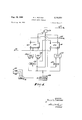
- FIGURE la is a chart illustrating positioning and damping voltages, in connection with a-pawl and rack arrangement, in accordance with the present invention.
- FIGURE lb includes waveforms illustrating various voltages, being plotted as voltage versus distance, presented for the purpose of describing the present invention
- FIGURE 1c is waveforms, illustrating error voltage versus time, presented for purposes'of explanation
- FIGURE 2 is a block diagram illustrating the present invention
- FIGURE 3 is a schematic diagram illustrating in greater detail some of the features involved in the present invention.
- FIGURE 4 is a block diagram illustrating some of the logical functions which may be incorporated into the present invention.
- a curve 10 representing a velocity voltage, which may be present in the system at the time that a pawl 14 is Vdisposed between D two teeth 16 and 18 of a positioning rack 20.
- a curve 12 represents the constant positioning voltage.
- An area between curves 12 and 1t) represents an error voltage, which may be present in the system when the pawl 14 is disposed between the two teeth 16 and 18.
- the pawl 14 may be connected to a mechanism 15, which may include the positioning mechanisms and magnetic head carrying carriage.
- a mechanism 15 which may include the positioning mechanisms and magnetic head carrying carriage.
- the details of such a mechanism are Well known to those skilled in the art.
- a description of one such positioning mechanism with which the present invention may be employed may be found in a copending patent application of H. F. Welsh, Serial Number 39,406, filed June 28, 1960, entitled Protective Release Mechanism and assigned to the same assignee as the present invention.
- An example of the magnetic head which may be suitably connected by means of a pulley or other suitable means to the positioning mechanism may be found in another co-pending application of F. X. Kanamuller, Serial Number 5,873, viewed, February 1, 1960 entitled Magnetic Head Positioning System, and assigned to the same assignee as the present invention.
- a waveform 22 represents a driving voltage for driving the pawl 14 against the tooth 18 and maintaining it in that position.
- a waveform 23 represents a gating signal.
- a waveform 24 represents a velocity voltage and a Waveform 25 represents a gating signal.
- the signiiicance of the various waveforms illustrated will be seen more clearly when the subsequent gures are described.
- a driving voltage such as represented by the curve 22 in FIGURE 1b, is applied from an input terminal 26 through a gate circuit 28 to a summing circuit Si).
- a tachometer 32 is associated with a driving motor 34 to develop a velocity voltage.
- the velocity voltage is applied to a clipping circuit 36 through an amplifier 38.
- the output voltage from the clipping circuit 36 is also applied to the summing circuit 30 through a gating circuit 40.
- the polarity of the voltage on the gating circuit 4l) is opposite in phase from the voltage developed at the gating circuit 28.
- the voltage at the line 42. is applied through an amplier 44 to drive the motor 34.
- the motor 34 produces a torque to urge the pawl 14 against the tooth 18 (FIG. la) and to maintain the pawl at a set position.
- a gate generator circuit 46 is used to produce a gate signal at the line 48 to inhibit the gating circuit 49 for a predetermined period of time. During this period, no velocity voltage is applied to the summing circuit 30.
- the inhibitory signal at the line 48 is removed to permit a velocity signal to pass from the clipping circuit 36 through the gating circuit 40 to the summing circuit 30.
- the driving voltage at the input terminal 26 is combined with the velocity voltage developed by the tachometer 32.
- the gating signal applied from the gate generator circuit 46 to the gating circuit 40 is represented by the waveform 25 of FIGURE 1c. It may be seen from the waveforms 22 and 24 that after a predetermined period of time, a maximum velocity Voltage from the clipping circuit 36, i.e., waveform 24, is applied to the summing circuit 30.
- a maximum acceleration during the initial period of operation is achieved by inhibiting the velocity damping voltages.
- tc a maximum acceleration during the initial period of operation.
- damping signal 24 drops below a certain value, as determined by the clipping circuit 36, the velocity voltage is no longer limited.
- td The time that the velocity voltage is limited. Consequently, during the settling down period of the pawl 14, designated ts, a maximum damping voltage is applied to the summing circuit Si?. This results in the pawl 14- coming to a rest position in a minimum amount of time.
- a driving voltage as represented by the curve 22 of FIG- URE lb
- This higher amplitude is illustrated by a dotted curve 52 and may be applied to a system for a period of time designated as te.
- an additional gating circuit 54 provides a gating signal 57 to permit the gate circuit 28 to pass a larger signal voltage for the time period designated tc.
- a driving voltage of additional amplitude may be desirable in order to overcome the mechanical intertia within a system when the pawl 14 is in a stationary or moving slowly prior to the application of reverse torque.
- FIGURE 3 a detailed schematic diagram including the main circuits of FIGURE 2 is illustrated.
- the driving voltage is applied from the input terminal 26 to the emitter of a transistor 55, which may be the circuit incorporated in the block 28 of FIG- URE 2.
- a gating signal is applied from a terminal 56 to the base of the transistor 55.
- the terminal 56 may be from the gate generator 54 (FIGURE 2).
- the circuit parameters associated with the transistor 55 are such that it is either conducting or non-conducting.
- the output signal from transistor 55 is applied to a summing circuit 30 which includes resistors 58, 60 and 62.
- the voltage at the point 64 of the summing circuit 30 is applied to the servo motor 34 when a movable arm 66 of the relay 72 is closed to engage a pair of contacts 68 and 70.
- the coil 74 of the relay 72 is energized by a signal from a circuit designated as a reverse circuit 76.
- the reverse circuit 76 may be a form of zero error voltage detector which may, for example, become operative when a pawl 14 (FIGURE la) is disposed between two selected teeth 16 and 18 of rack 20.
- the paWl may be in this position as a result of the first and second servo operations previously discussed.
- a source of velocity voltage for example from the tachometer 32 of FIGURE 2, is applied from an input terminal '78 to the clipping circuit 36.
- the clipping circuit includes a pair of diodes 80 and 82.
- the output voltage from the clipping circuit atthe point 83 is applied to the base of a transistor 84.
- a gating signal which may be from the gate generator 46 of FIGURE 2, is applied from an input terminal 86 to the base of a transistor 88.
- the transistor 8S is either conducting or non-conducting dependent upon the signal applied to the terminal 86.
- a gating signal at the terminal 86 applied to the base thereof causes the transistor 88 to conduct thereby providing a low impedance path to ground for the velocity voltage applied to the input terminal 78.
- the transistor 8S becomes non-conducting thereby permitting the velocity voltage at theinput terminal 78 to be applied to the clipping circuit 36.
- the output voltage representing the-applied velocity voltage is applied from the emitter of the transistor 84 through. a capacitor 90 to the summing circuit 30.
- the phase relationship between the voltage applied to the summing circuit from the input terminal 26 and from the velocity voltage are opposite.
- a system can generally be designed so that the velocity voltage providing a damping effect is applied after the maximum acceleration of a pawl has been reached to minimize the likelihood of mechanical damage to the pawl or other associated mechanical parts when the pawl strikes against the positioning rack.
- the velocity signal is limited after maximum acceleration is reached in such a way that approximately constant speed of the pawl is achieved.
- the velocity voltage at the terminal 78 drops below the voltage level required to operate the diodes 80 and 82 and isnot limited by the clipping circuit 36 since the diodes 80 and 82 become non-conducting. Because the velocity voltage is not limited by the diodes, the damping voltage is not limited and final position of a pawl or carriage driving by a motor is reached in a minimum of time.
- a reverse torque switching system synchronization logic diagram The purpose of this circuit is to generate gating signals related to the driving voltage and the velocity voltage.
- the driving gating signal is used to synchronize the application of the reverse torque to the servo with the peak value of the line voltage in order to speed servo response.
- the velocity gating signal is used to inhibit the application of the velocity signal during the rack moving cycle Vand during the early part of the reverse torque phase. This allows undampened acceleration of a carriage so that the carriage can follow the rack during the racks moving cycle and so that the response time can be minimized during the reverse torque phase.
- flip flops 92 and 94 are cleared by a signal applied to a terminal 9d.
- This signal may be from a change of address amplifier in a positioning system designating that a new address must be sought by the carriage. No change in the hip flops 92 and 94 can occur until a signal is received from an AND gate circuit 98.
- Various other circuits associated with a computer may be connected to terminals ltltl, 103 and 104. For example, one of the terminals lill) may be employed to assure that no signal is developed at the output of the AND gate v9S during the forward or Aiip flops 92 and 94.
- the second terminal V103 may be connected to receive a. signal indicating that a relay or other means has been operated to actuate the pawl mechanism and to cause the pawl 14 to be in an extended position.
- Gate circuit liiS which receives the conditioning level from the R output of the flip flop 94 is the only one of the three gate circuits 16S, 1li) and 112 which passes the tirst pulse from the gate circuit 98. This rst pulse, passed by the gate circuit 16S, sets the flip flop 92.
- the second pulse from the AND gate 98 passes through the gate circuit lll and sets the tiip ilop 94.
- the second pulse also passes through a gate circuit 16S, but has no effect on the flip liep 92 which 4is already set.
- a time delay provided by a delay circuit 1ll6, during the time that the iiip flop 94 is in its S state, insures that the inhibited level is maintained at the gate circuit 11i) during the second pulse period.
- the inhibited level is gone from the gate circuit lli).
- an inhibited level is present at the gate circuit 1%, hence the ilip flop 9d is set.
- the third pulse resets the flip ilcp 92. This completes the operation of the synchronization circuit until such time as a reset signal appears at the terminal 96, since succeeding pulses passed by the gate circuit 98 have no further affect on the flip ilops 92 and 9d.
- the two flip flops 92 and 94 are initially reset.
- the first pulse through the gate 9S sets the flip ilop 92.
- the second pulse sets the ip tlop 94.
- the third pulse resets the flip flop 92.
- the driving voltage gating signal is developed at the output terminal from an OR circuit 118 which is connected to the S outputs of the two
- the gating signal appears when the ilip iiop 92 is set by the iirst pulse and continues until the two flip flops 92 and 94 are reset by a signal applied to the terminal 96.
- the pulses applied t0 the terminal 105 coincide with the peaks of the reverse torque signal voltage so that the reverse torque is applied to drive the servo motor 34 (FIGURE 2) just at it reaches its peak value.
- the velocity gating signal applied to the output terminal 122 is taken from the R output of the iiip iiop 92.
- This signal may be initially zero Volts and drops to minus 10 volts when the 'Flip iiop 92 is set by the rst pulse from the gate circuit 93. This voltage returns to zero volts when the flip flop 9?. is reset by the third pulse from the gate circuit 9S. Since there are two pulses for each cycle of the reverse torque signal, the velocity gating signal is negative for one cycle of the'signal.v This negative gating signal removes the velocity signal voltage for one cycle of theV reverse torque signal.
- the timing of the driving and velocity signals is illustrated in FIGURES lb and lc.
- the present invention has provided means ⁇ for attaining fast nal positioning of a carriage over a selected portion of a drum. This has been accomplished with a servo motor of low carrier frequency type by providing a quick initial acceleration of a driving servo motor to reach maximum speed, synchronizing the servo motor from the line carrier frequency, and then providing a damping signal after a predetermined time interval. All this is accomplished Without slowing down the moving mechanism. Once the pawl has hit the rack, high damping is provided by using an amplified and clipped velocity signal thereby achieving a quick settling down of the carriage and its associated mechanical parts.
- an extendible and retractable pawl movable mounted to said carriage and disposed to engage one of the teeth of said rack when in an extended position and to be free of said rack when in a retracted position, a motor for urging said pawl against one ot said teeth when said pawl is in an extended position, a source of driving Voltage for driving said motor, a tachometer associated with said motor to produce a velocity voltage representative of the velocity of said carriage, means for applying said driving voltage to urge said pawl against a selected tooth of said rack when said pawl is in an extended position to maintain said carriage in a tixed position relative to said rack, a gating circuit, means for appiying said velocity voltage through said gating circuit to said motor to provide damping of the movement of said carriage during the final stage of a positioning operation, a gate generator circuit to produce gating signals, and means for applying said gating
- an extendible and retractable pawl movably mounted to said carriage and disposed to engage one of the teeth of said rack when in an extended position and to be free of said rack when in a retracted position, a motor for urging said pawl against one of said teeth when said pawl is in an extended position, a source of driving voltage for driving said motor, a tachometer associated with said motor to produce a velocity voltage representative of the velocity of said carriage, means for applying said driving Voltage to urge said pawl against a selected tooth of said rack when said pawl is in an extended position to maintain said carriage in a fixed position relative to said rack, a limiter circuit, means for applying said veiocity voltage to said limiter circuit, a gating circuit, means for applying the output voltage from said limiter circuit through said gating circuit to said motor to provide dampriage movement during said predetermined time period.
- an extendible and retractable pawl movably mounted to said carriage and disposed to engage one of the teeth of said rack when in an extended position and to be free of said rack when in a retracted position, a motor for urging said pawl against one of said teeth when said pawl is in an extended position, a source of driving voltage for driving said motor, a tachometer associated with said motor to produce a velocity voltage representative of the velocity of said carriage, means for applying said driving voltage to urge said pawl against a selected tooth of said rack when said pawl is in an extended position to maintain said carriage in a xed position relative to said rack, a limiter circuit, means for applying said velocity voltage to said limiter circuit, a gating circuit, means for applying the output voltage from said limiter circuit through said gating circuit to said motor to provide damping of the movement of said carriage during ,the final stage of a positioning operation,
- a gate generator circuit to produce gating signals, means for applying said gating signals to said gating circuit to inhibit the application or" said velocity voltage to said motor for a predetermined time period to minimize the damping of the movement of said carriage during said predetermined time period, and means for increasing the amplitude of said driving voltage for a portion of said predetermined time period to permit maximum acceleration of said carriage.
- said last named means includes a second gating circuit and a second gate generator for generating second gating signals, means for applying said second gating signals to said second gate generator, said driving voltage being applied
Landscapes
- Physics & Mathematics (AREA)
- General Physics & Mathematics (AREA)
- Engineering & Computer Science (AREA)
- Automation & Control Theory (AREA)
- Control Of Position Or Direction (AREA)
- Moving Of Heads (AREA)
Priority Applications (5)
| Application Number | Priority Date | Filing Date | Title |
|---|---|---|---|
| NL268496D NL268496A (it) | 1960-08-24 | ||
| US51750A US3145331A (en) | 1960-08-24 | 1960-08-24 | Detent servo system |
| DE1424463A DE1424463C3 (de) | 1960-08-24 | 1961-08-17 | Servosteuersystem für Magnettrommelspeicher |
| CH981561A CH412005A (it) | 1960-08-24 | 1961-08-22 | Servodispositivo di comando per memoria a tamburo magnetico |
| GB30316/61A GB986396A (en) | 1960-08-24 | 1961-08-22 | Detent servo system |
Applications Claiming Priority (1)
| Application Number | Priority Date | Filing Date | Title |
|---|---|---|---|
| US51750A US3145331A (en) | 1960-08-24 | 1960-08-24 | Detent servo system |
Publications (1)
| Publication Number | Publication Date |
|---|---|
| US3145331A true US3145331A (en) | 1964-08-18 |
Family
ID=21973171
Family Applications (1)
| Application Number | Title | Priority Date | Filing Date |
|---|---|---|---|
| US51750A Expired - Lifetime US3145331A (en) | 1960-08-24 | 1960-08-24 | Detent servo system |
Country Status (5)
| Country | Link |
|---|---|
| US (1) | US3145331A (it) |
| CH (1) | CH412005A (it) |
| DE (1) | DE1424463C3 (it) |
| GB (1) | GB986396A (it) |
| NL (1) | NL268496A (it) |
Cited By (2)
| Publication number | Priority date | Publication date | Assignee | Title |
|---|---|---|---|---|
| US3895281A (en) * | 1970-09-16 | 1975-07-15 | Billi Spa | Linear motor positioning device with position detent means |
| US4130844A (en) * | 1976-10-26 | 1978-12-19 | Xerox Corporation | Method and means for tracking magnetic tracks |
Citations (4)
| Publication number | Priority date | Publication date | Assignee | Title |
|---|---|---|---|---|
| US2726359A (en) * | 1951-07-06 | 1955-12-06 | Gen Controls Co | Directional multiposition motor control |
| US2848677A (en) * | 1956-07-19 | 1958-08-19 | Collins Radio Co | Shaft positioning control mechanism |
| US2913654A (en) * | 1953-11-12 | 1959-11-17 | Leeds & Northrup Co | High-speed self-balancing servosystem |
| US2940026A (en) * | 1957-06-18 | 1960-06-07 | Gen Electric | Variable bandwith servomechanism |
-
0
- NL NL268496D patent/NL268496A/xx unknown
-
1960
- 1960-08-24 US US51750A patent/US3145331A/en not_active Expired - Lifetime
-
1961
- 1961-08-17 DE DE1424463A patent/DE1424463C3/de not_active Expired
- 1961-08-22 CH CH981561A patent/CH412005A/it unknown
- 1961-08-22 GB GB30316/61A patent/GB986396A/en not_active Expired
Patent Citations (4)
| Publication number | Priority date | Publication date | Assignee | Title |
|---|---|---|---|---|
| US2726359A (en) * | 1951-07-06 | 1955-12-06 | Gen Controls Co | Directional multiposition motor control |
| US2913654A (en) * | 1953-11-12 | 1959-11-17 | Leeds & Northrup Co | High-speed self-balancing servosystem |
| US2848677A (en) * | 1956-07-19 | 1958-08-19 | Collins Radio Co | Shaft positioning control mechanism |
| US2940026A (en) * | 1957-06-18 | 1960-06-07 | Gen Electric | Variable bandwith servomechanism |
Cited By (2)
| Publication number | Priority date | Publication date | Assignee | Title |
|---|---|---|---|---|
| US3895281A (en) * | 1970-09-16 | 1975-07-15 | Billi Spa | Linear motor positioning device with position detent means |
| US4130844A (en) * | 1976-10-26 | 1978-12-19 | Xerox Corporation | Method and means for tracking magnetic tracks |
Also Published As
| Publication number | Publication date |
|---|---|
| DE1424463C3 (de) | 1974-12-12 |
| NL268496A (it) | |
| DE1424463B2 (de) | 1974-04-25 |
| DE1424463A1 (de) | 1968-10-17 |
| GB986396A (en) | 1965-03-17 |
| CH412005A (it) | 1966-04-30 |
Similar Documents
| Publication | Publication Date | Title |
|---|---|---|
| US2700155A (en) | Electrical signaling system | |
| US2794123A (en) | Electrical delay circuits | |
| US3072855A (en) | Interference removal device with revertive and progressive gating means for setting desired signal pattern | |
| US3209338A (en) | Zero detector for a positioning system | |
| US3478178A (en) | Switched frequency and phase comparator | |
| US3145331A (en) | Detent servo system | |
| US2804605A (en) | Magnetic recording playback circuits | |
| US3209268A (en) | Phase modulation read out circuit | |
| US2801407A (en) | Timing channel recording | |
| US3668494A (en) | Constant displacement stopping control | |
| GB1484885A (en) | Recording of data on a movable data carrier | |
| US3191058A (en) | Detection circuit utilizing opposite conductiviity transistors to detect charge on acapacitor | |
| US3029389A (en) | Frequency shifting self-synchronizing clock | |
| US2789224A (en) | Controlled pulse generator | |
| US3028589A (en) | Motion digitizer | |
| US2697166A (en) | Self-triggered blocking oscillator | |
| GB758874A (en) | Systems for generating high definition pulses in a magnetic device | |
| GB1162447A (en) | Improvements relating to Electric Motor Control Circuits. | |
| US3795008A (en) | Method for the discrete sampling of co-related values of two or more variables | |
| US3144638A (en) | Time compression storage circuit | |
| US3922610A (en) | Pulse anti coincidence methods and circuits | |
| US2815498A (en) | Magnetic memory channel recirculating systems | |
| US3087143A (en) | Time delay device for analogue computer | |
| GB1345237A (en) | Servo system | |
| GB796178A (en) | Apparatus for checking the time delay between earlier and later pulses |