US3142153A - Solid propellant rocket thrust vectoring system - Google Patents
Solid propellant rocket thrust vectoring system Download PDFInfo
- Publication number
- US3142153A US3142153A US116016A US11601661A US3142153A US 3142153 A US3142153 A US 3142153A US 116016 A US116016 A US 116016A US 11601661 A US11601661 A US 11601661A US 3142153 A US3142153 A US 3142153A
- Authority
- US
- United States
- Prior art keywords
- skirt
- nozzle
- fixed section
- rocket
- deflected
- Prior art date
- Legal status (The legal status is an assumption and is not a legal conclusion. Google has not performed a legal analysis and makes no representation as to the accuracy of the status listed.)
- Expired - Lifetime
Links
- 239000004449 solid propellant Substances 0.000 title description 3
- 239000007789 gas Substances 0.000 claims description 17
- 230000006835 compression Effects 0.000 claims description 13
- 238000007906 compression Methods 0.000 claims description 13
- 230000033001 locomotion Effects 0.000 claims description 7
- RZVHIXYEVGDQDX-UHFFFAOYSA-N 9,10-anthraquinone Chemical compound C1=CC=C2C(=O)C3=CC=CC=C3C(=O)C2=C1 RZVHIXYEVGDQDX-UHFFFAOYSA-N 0.000 description 5
- 235000015842 Hesperis Nutrition 0.000 description 3
- 235000012633 Iberis amara Nutrition 0.000 description 3
- 230000000694 effects Effects 0.000 description 3
- 230000003628 erosive effect Effects 0.000 description 3
- 230000007935 neutral effect Effects 0.000 description 3
- 238000007789 sealing Methods 0.000 description 3
- 230000000712 assembly Effects 0.000 description 1
- 238000000429 assembly Methods 0.000 description 1
- 230000003247 decreasing effect Effects 0.000 description 1
- 230000001627 detrimental effect Effects 0.000 description 1
- 230000007613 environmental effect Effects 0.000 description 1
- 238000009434 installation Methods 0.000 description 1
- 230000003993 interaction Effects 0.000 description 1
- 238000012986 modification Methods 0.000 description 1
- 230000004048 modification Effects 0.000 description 1
- 239000007787 solid Substances 0.000 description 1
- 230000002277 temperature effect Effects 0.000 description 1
Images
Classifications
-
- F—MECHANICAL ENGINEERING; LIGHTING; HEATING; WEAPONS; BLASTING
- F02—COMBUSTION ENGINES; HOT-GAS OR COMBUSTION-PRODUCT ENGINE PLANTS
- F02K—JET-PROPULSION PLANTS
- F02K9/00—Rocket-engine plants, i.e. plants carrying both fuel and oxidant therefor; Control thereof
- F02K9/80—Rocket-engine plants, i.e. plants carrying both fuel and oxidant therefor; Control thereof characterised by thrust or thrust vector control
- F02K9/84—Rocket-engine plants, i.e. plants carrying both fuel and oxidant therefor; Control thereof characterised by thrust or thrust vector control using movable nozzles
Definitions
- the instant invention relates generally to thrust vectoring systems for rockets for control of the flight of the latter, and more particularly to a new and improved rocket nozzle structure for adjusting the jet deflection to produce vectoring of the rocket for pitch, yaw and roll control.
- the main thrust nozzles are constructed so that the main jet can be deflected in a controlled manner to provide the necessary flight control.
- a more eflicient and practical system is achieved because the principal nozzle structure which provides the main propulsion serves the additional function of providing control thrust to produce pitch, yaw and roll of the rocket for flight control.
- the preferred embodiment of this invention minimizes the erosion and temperature problem, and makes the use of a deflectable skirt nozzle practical.
- the moving elements of the deflectable skirt nozzle embodying the instant invention are so arranged that the proper reliability and service life is achieved with a simple light weight structure suitable for use in the field of rocketry.
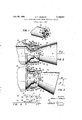
- FIGURE 1 is a fragmentary perspective view showing one preferred nozzle arrangement suitable for providing complete flight control of a rocket
- FIGURE 2 is an enlarged side elevation partially in longitudinal section illustrating a preferred embodiment incorporating this invention with the nozzle in neutral po-' sition;
- FIGURE 3 is a view similar to FIGURE 2 showing the nozzle in a deflected position
- FIGURE 4 is a schematic illustration of the flow through a deflectable nozzle illustrating the aerodynamic functions of the preferred nozzle.
- FIGURE 1 is a schematic representation of the thrust or nozzle end of a rocket 10.
- Mounted on the nozzle end 11 is a cluster of four rocket nozzles 12.
- Each of the nozzles 12 can be connected to a separate rocket motor, or to a single rocket motor, depending upon the particular capacities and design re quirement of the system.
- Each of the nozzles 12 has a skirt 13 which can be deflected in a plane perpendicular to a plane containing the central axis of the rocket and the nozzle.
- Each of the jets exhausting through the nozzles 12 can therefore be deflected in the plane of deflection of skirt 13 to provide the necessary flight control of the rocket 10.
- a force couple is developed which will provide roll control of the rocket 10. Conversely, if a pair of diametrically opposite nozzles is deflected in the same direction, a force can be developed providing pitch or yaw control. Thus, by selected control of the deflection of the nozzles 12 pitch, yaw and roll control of the rocket can be achieved.
- FIGURES 2 and 3 there is illustrated therein in detail the structure of a nozzle 12.
- Each of the nozzles 12 embodies the same structure, and therefore, it will suflice to describe the structure of one nozzle 12, it being understood that the description applies to each of the nozzles 12.
- the nozzle 12 comprises two basic assemblies, namely a fixed assembly 14 and a defiectable skirt assembly 16, the latter being the adjustable assembly which is operative to provide pitch, yaw and roll control of the rocket.
- the fixed assembly 14 includes an annular inlet member 17 secured to the nozzle end 11 of the rocket 10 by a plurality of suitable bolts 28.
- the innerwall 18 of the inlet member 17 is formed as a surface of revolution generated around a central axis 19.
- the innerwall 18 extends from the forward end with a decreasing diameter to a throat 21 of minimum diameter.
- an outlet member 22 mounted on the rear end of the inlet member 17 is an outlet member 22 also formed with an innerwall 23 which is a surface of revolution generated around the central axis 19, the diameter of which increases as it extends from the throat 21 to an outer end 24.
- the outlet member 22 is formed with a spherical outer surface 26 ahead of the outer end 24, which has a center of curvature at the point of intersection of the transverse axis 31 with the central axis 19.
- a plurality of suitable bolts 28 mount the outlet member 22 on the inlet member 17, and are preferably disposed adjacent to the outer surface, so that they will be located remote from the hot gas flowing through the nozzle 12.
- a pair of opposed trunnion arms 29 are formed integrally with the inlet member 17 and extend rearwardly in an axial direction along the opposite sides of the nozzle 12 and provide a trunnion mounting for the deflectable skirt assembly 16, which is thus mounted for rotation' on oppositely disposed diametrically extending trunnions 27 having an axis of rotation 31 which intersects the central axis 19. Therefore, the skirt assembly 16 can be deflected from the neutral position in either direction upwardly or downwardly about the axis 31, as seen in FIGURE 3.
- the skirt 13 is formed with a flaring innerwall 32 which is a surface of revolution generated around the central axis 33 of the skirt.
- the two axes 19, 33 are coincident, but when the skirt 13 is deflected, as seen in FIGURE 3 the axis 33 is divergent with respect to the central axis 19 but intersects it at the point of intersection of the transverse axis 31 with the axis 19.
- a pair of diametrically oppositely disposed pneumatic actuators 34 are connected between the fixed assembly 14 and the skirt assembly 16.
- the actuators 34 include a cylinder 36 pivotally mounted on pin 37 in a boss 38 formed on the inlet member 117.
- the piston 33 is pivotally mounted on pin 41 in a boss 42 formed on the skirt assembly 16.
- Actuators 34 of the cylinder and piston type are preferred because of the high environmental temperature. The seals in the actuators 34 can therefore be such that a limited amount of leakage can be tolerated without causing system failure.
- the actuators 34 are controlled by a suitable guidance system incorporated in the rocket 19, through suitable valving devices and the like which are not included in the instant invention.
- cylinder and piston pneumatic actuators 34 have been illustrated as the preferred structure, it will be understood that other types of actuators, such as screw jack actuators, could be utilized. Also, the use of two diametrically oppositely disposed actuators 34 is not essential, and, by way of example one double acting ac tuator can be utilized to provide the desired control.
- FIGURE 4 for a description of the aerodynamic characteristics of the deflectable nozzle incorporating this invention.
- the jet deflection is greater than the geometric deflection of the skirt or exit section of the nozzle.
- This phenomenon which is schematically illustrated in FIGURE 4 is described hereinafter with the assumption that the flow is two dimensional, and that the channel depth is constant rather than three dimensional as in the actual application. Inlet flow at a Mach number greater than one is from the left.
- the upper and lower channel walls 51, 52, respectively are deflected through a small angle S. This angle S is assumed to be small enough so that for the purposes of this discussion the compression accompanying the turn at the point A can be considered isentropic.
- a compression wave 53 is set up at the point A and extends obliquely across the channel and intersects the lower wall at D.
- an expansion wave 54 emanates from the point B and extends obliquely across the channel and intersects the upper wall 51 at C.
- All stream lines crossing the expansion wave 54 after passing through the compression wave '3 are deflected through an additional angle S, providing that the wall between A and C terminates at C to prevent the reflection of the expansion wave 54 at the upper wall.
- all stream lines passing through the compression wave 53 after first crossing the expansion wave 54 are deflected through an additional angle S providing the lower wall terminates at D to prevent a reflected compression wave at this point.
- the double deflected stream lines are represented by the portions numbered 61 and 62.
- the structure illustrated shows a deflectable skirt nozzle employing a single plane of deflection of the exit skirt about a normal transverse axis.
- This arrangement is representative of most of the applications that have been considered.
- a plurality of nozzles as illustrated in FIGURE 1, is used with two or more hinge line axes to provide yaw, pitch and roll control of the direction of flight.
- the deflectable skirt nozzle is, however, made up of axially symmetrical sections and in eflect employs a ball and socket joint.
- the two major sections of the nozzle can obviously then be coupled through a gimbal arrangement which would provide 360 deflection of the exhaust jet.
- a single nozzle or two cooperating nozzles could be used to provide the desired control of the rocket.
- a flexible nozzle or deflectable nozzle incorporates a joint between the skirt assembly 16 and the fixed assembly 14 which is located in the lower pressure down stream zone following the throat 21.
- a scraper or sealing ring 43 is mounted on the forward end of the skirt assembly 16 and engages the spherical surface or wanes. Since the skirt assembly 16 is journaled for rotation about an axis intersecting the center of curvature of the spherical wall 26 the sealing ring 43 rides smoothly on the outlet member 22. The sealing ring is also positioned forward from the outer end 24 away from the stream of hot gases flowing through the nozzle. This joint and seal function satisfactorily because it is not exposed to high pressure and is protected from the high temperature of the gases by the outlet member 22.
- a convergent, divergent rocket nozzle comprising a fixed section having a flow passage including the nozzle throat open at its divergent outer end, a skirt member having a flow passage open to the outer end of the fixed section flow passage and closely overlapping said outer end to form a substantially tight joint, means mounting said skirt for sliding pivotal movement relative to said fixed section between a first position wherein said flow passages are aligned and deflected positions wherein said flow passages are inclined relative to each other, gases flowing through said passages with a velocity greater than Mach one, said fixed section and skirt member cooperating when in said deflected positions to establish a compression wave and an expansion wave each emanating from the joint between said fixed section and skirt member and crossing within said skirt member flow passage whereby said gases flowing through said passages are defiected by passage through said waves to a deflectable angle greater than the angle of deflection of said skirt member 2.
- a convergent, divergent rocket nozzle comprising a fixed section including a minimum cross section throat and a flaring portion downstream therefrom terminating at the outer end with said flaring portion having a curved surface thereon, a pair of trunnions extending from said fixed section, a skirt member having a curved surface thereon cooperable with said curved surface on said flaring portion of said fixedsection to form a substantially tight joint therebetween, said skirt being mounted for pivotal movement about said trunnions relative to said fixed section between a first position wherein said flow passages are alined and deflected positions wherein said flow passages are inclined relative to each other, means cooperable with said skirt to effect said pivotal movement, gases flowing through said passages with a velocity greater than Mach one, said fixed section and skirt member cooperating when in said deflected positions to establish a compression wave and an expansion wave each emanating from the joint between said fixed section and skirt member and crossing within said skirt member flow passage whereby said gases flowing through said passages are deflected by passage through
- a convergent, divergent rocket nozzle according to claim 2 wherein said means cooperable with said skirt comprises a power actuator engageable with said fixed section and skirt operable to effect selective pivotal move ment of said skirt relative to said fixed section upon actuation thereof.
- a convergent, divergent rocket nozzle comprising a fixed section having a flow passage including the nozzle throat and a flaring portion downstream thereof open at its outer end with said flaring portion having a curved surface thereon, a skirt member of substantially circular cross-section engageable with said fixed section to form a substantially tight joint therebetween, means for mounting and providing pivotal movement of said skirt member on said fixed section for pivotal movement of said skirt member between a position wherein said flow passages are alined and deflected positions wherein said flow passages are inclined relative to each other, seal means on said skirt engageable with said curved surface on said flared portion, gases flowing through said passages with a velocity greater than Mach one with said seal being operable to prevent passage of said gases between said fixed section and said skirt, said fixed section and skirt member cooperating when in said deflected positions to establish a compression wave and an expansion wave each emanating from the joint between said fixed section and skirt member and crossing within said skirt member flow passage whereby said gases flowing through said passages are deflected by passage through
- a convergent, divergent rocket nozzle comprising a fixed assembly having an axially extending innerwall generated as a surface of revolution about a central axis defining a flow passage, said innerwall including an inlet portion extending with reducing radius to a medium radius throat and an exhaust portion extending with increasing radius from said throat to an outer end, a skirt having an innerwall generated as a surface of revolution about a skirt axis defining a flow passage, means mounting said skirt on said fixed assembly to form a substantially tight joint therebetween, said skirt being movable from an alined flow passage position wherein said skirt axis and central axis are coaxial and deflected positions wherein they are non-coaxial, a substantially spherical outer surface on said fixed assembly adjacent to said outer end having a center of curvature at said predetermined point, a seal on said skirt engaging said surface, gases flowing through said passages with a velocity greater than Mach one, said seal effective to prevent passage of said gases between said fixed section and said skirt, actuator means operative
Landscapes
- Engineering & Computer Science (AREA)
- Chemical & Material Sciences (AREA)
- Combustion & Propulsion (AREA)
- Mechanical Engineering (AREA)
- General Engineering & Computer Science (AREA)
- Testing Of Engines (AREA)
Description
July 28, 1964 v, HENSLEY 3,142,153
SOLID FROPELLANT ROCKET THRUST VECTORING SYSTEM Filed June 9, 1961 Illllll FIG. 3
INVENTOR.
REECE V. HENSLEY ATTORNEY if 3| Q 29 United States Patent 3,142,153 SOLID PROPELLANT ROCKET THRUST VECTORING SYSTEM Reece V. Hensley, Potomac, Md, assignor to Pneumo- Dynamics Corporation, leveland, Ohio, a corporation of Delaware Filed June 9, 1961, Ser. No. 116,016 Claims. (Cl. 60-35.55)
The instant invention relates generally to thrust vectoring systems for rockets for control of the flight of the latter, and more particularly to a new and improved rocket nozzle structure for adjusting the jet deflection to produce vectoring of the rocket for pitch, yaw and roll control.
In order to control the flight of a rocket, it is necessary to control the pitch, yaw and roll of the rocket. Various systems have been utilized for controlling the rocket flight by deflection of the rocket jet, but these have not been entirely satisfactory due to mechanical difficulties brought about by the extreme erosion and high temperature to which the nozzle is subjected. This has led to the use of auxiliary control nozzles remotely located with respect to the main rocket nozzle, which provide a secondary thrust to pitch, yaw and roll the rocket in flight. Such systems have the disadvantage of requiring additional nozzle structure, adding weight to the rocket not attributable to the principal propelling thrust, and produce a weight penalty which is detrimental to the propulsion structure, and therefore, constitutes an undesirable feature. In a rocket incorporating the instant invention the main thrust nozzles are constructed so that the main jet can be deflected in a controlled manner to provide the necessary flight control. A more eflicient and practical system is achieved because the principal nozzle structure which provides the main propulsion serves the additional function of providing control thrust to produce pitch, yaw and roll of the rocket for flight control. The preferred embodiment of this invention minimizes the erosion and temperature problem, and makes the use of a deflectable skirt nozzle practical. The moving elements of the deflectable skirt nozzle embodying the instant invention are so arranged that the proper reliability and service life is achieved with a simple light weight structure suitable for use in the field of rocketry.
It is an important object of this invention to provide a new and improved rocket nozzle structure incorporating an adjustable nozzle skirt operable to deflect the jet exhausting from the nozzle in a controlled manner to provide flight direction control for the rocket.
It is another important object of this invention to provide a new and improved nozzle structure incorporating an adjustable nozzle skirt portion mounted on a fixed nozzle portion with a seal between the fixed and movable nozzle portions that is protected against the damaging erosion and temperature effects of supersonic flow of extremely hot gases.
It is another important object of this invention to provide an adjustable nozzle for a rocket which provides complete flight control by adjustment of the nozzle to deflect the direction of thrust of the propulsion jet of the rocket.
It is still another object of this invention to provide a nozzle for control of the flight of rockets and the like, having a fixed throat portion and a flaring skirt portion adjustable to deflect the jet exhausting through the nozzle, wherein the joint between the adjustable skirt portion and the fixed throat portion of the nozzle is in a zone of low pressure, and is shielded against the intense heat developed during nozzle operation.
Further objects and advantages will appear from the following description and drawings wherein:
FIGURE 1 is a fragmentary perspective view showing one preferred nozzle arrangement suitable for providing complete flight control of a rocket;
FIGURE 2 is an enlarged side elevation partially in longitudinal section illustrating a preferred embodiment incorporating this invention with the nozzle in neutral po-' sition;
FIGURE 3 is a view similar to FIGURE 2 showing the nozzle in a deflected position; and
FIGURE 4 is a schematic illustration of the flow through a deflectable nozzle illustrating the aerodynamic functions of the preferred nozzle.
Referring to the drawings, FIGURE 1 is a schematic representation of the thrust or nozzle end of a rocket 10. Mounted on the nozzle end 11 is a cluster of four rocket nozzles 12. Each of the nozzles 12 can be connected to a separate rocket motor, or to a single rocket motor, depending upon the particular capacities and design re quirement of the system. Each of the nozzles 12 has a skirt 13 which can be deflected in a plane perpendicular to a plane containing the central axis of the rocket and the nozzle. Each of the jets exhausting through the nozzles 12 can therefore be deflected in the plane of deflection of skirt 13 to provide the necessary flight control of the rocket 10. If a pair of diametrically opposite nozzles 12 are deflected in opposite directions, a force couple is developed which will provide roll control of the rocket 10. Conversely, if a pair of diametrically opposite nozzles is deflected in the same direction, a force can be developed providing pitch or yaw control. Thus, by selected control of the deflection of the nozzles 12 pitch, yaw and roll control of the rocket can be achieved.
Referring to FIGURES 2 and 3, there is illustrated therein in detail the structure of a nozzle 12. Each of the nozzles 12 embodies the same structure, and therefore, it will suflice to describe the structure of one nozzle 12, it being understood that the description applies to each of the nozzles 12.
The nozzle 12 comprises two basic assemblies, namely a fixed assembly 14 and a defiectable skirt assembly 16, the latter being the adjustable assembly which is operative to provide pitch, yaw and roll control of the rocket.
The fixed assembly 14 includes an annular inlet member 17 secured to the nozzle end 11 of the rocket 10 by a plurality of suitable bolts 28. The innerwall 18 of the inlet member 17 is formed as a surface of revolution generated around a central axis 19. The innerwall 18 extends from the forward end with a decreasing diameter to a throat 21 of minimum diameter.
Mounted on the rear end of the inlet member 17 is an outlet member 22 also formed with an innerwall 23 which is a surface of revolution generated around the central axis 19, the diameter of which increases as it extends from the throat 21 to an outer end 24. The outlet member 22 is formed with a spherical outer surface 26 ahead of the outer end 24, which has a center of curvature at the point of intersection of the transverse axis 31 with the central axis 19. A plurality of suitable bolts 28 mount the outlet member 22 on the inlet member 17, and are preferably disposed adjacent to the outer surface, so that they will be located remote from the hot gas flowing through the nozzle 12.
A pair of opposed trunnion arms 29 are formed integrally with the inlet member 17 and extend rearwardly in an axial direction along the opposite sides of the nozzle 12 and provide a trunnion mounting for the deflectable skirt assembly 16, which is thus mounted for rotation' on oppositely disposed diametrically extending trunnions 27 having an axis of rotation 31 which intersects the central axis 19. Therefore, the skirt assembly 16 can be deflected from the neutral position in either direction upwardly or downwardly about the axis 31, as seen in FIGURE 3.
The skirt 13 is formed with a flaring innerwall 32 which is a surface of revolution generated around the central axis 33 of the skirt. When the skirt 13 is in the neutral position, as seen in FIGURE 2 the two axes 19, 33 are coincident, but when the skirt 13 is deflected, as seen in FIGURE 3 the axis 33 is divergent with respect to the central axis 19 but intersects it at the point of intersection of the transverse axis 31 with the axis 19.
In order to control the position of the skirt assembly 16, a pair of diametrically oppositely disposed pneumatic actuators 34 are connected between the fixed assembly 14 and the skirt assembly 16. The actuators 34 include a cylinder 36 pivotally mounted on pin 37 in a boss 38 formed on the inlet member 117. The piston 33 is pivotally mounted on pin 41 in a boss 42 formed on the skirt assembly 16. Actuators 34 of the cylinder and piston type are preferred because of the high environmental temperature. The seals in the actuators 34 can therefore be such that a limited amount of leakage can be tolerated without causing system failure. The actuators 34 are controlled by a suitable guidance system incorporated in the rocket 19, through suitable valving devices and the like which are not included in the instant invention.
Although cylinder and piston pneumatic actuators 34 have been illustrated as the preferred structure, it will be understood that other types of actuators, such as screw jack actuators, could be utilized. Also, the use of two diametrically oppositely disposed actuators 34 is not essential, and, by way of example one double acting ac tuator can be utilized to provide the desired control.
Reference is now made to FIGURE 4 for a description of the aerodynamic characteristics of the deflectable nozzle incorporating this invention. In a defleotable nozzle incorporating this invention the jet deflection is greater than the geometric deflection of the skirt or exit section of the nozzle. This phenomenon which is schematically illustrated in FIGURE 4 is described hereinafter with the assumption that the flow is two dimensional, and that the channel depth is constant rather than three dimensional as in the actual application. Inlet flow at a Mach number greater than one is from the left. At the points A and B the upper and lower channel walls 51, 52, respectively, are deflected through a small angle S. This angle S is assumed to be small enough so that for the purposes of this discussion the compression accompanying the turn at the point A can be considered isentropic. A compression wave 53 is set up at the point A and extends obliquely across the channel and intersects the lower wall at D. Similarly, an expansion wave 54 emanates from the point B and extends obliquely across the channel and intersects the upper wall 51 at C. These two waves 53, 54 intersect within the channel at point E and interact. However, as a first approximation to the axial field, in the case of small wall angles S they can be considered to cross but to have no mutual interaction.
In the triangular region defined by the points AEC all stream lines crossing the compression wave 53 are deflected downward by an angle S as shown by the portions of stream lines 56, 57. Similarly, in the triangular region defined by the points BED stream lines crossing the expansion wave 54 are deflected downward by an angle S as shown by the portions of the stream lines 58, 59.
All stream lines crossing the expansion wave 54 after passing through the compression wave '3 are deflected through an additional angle S, providing that the wall between A and C terminates at C to prevent the reflection of the expansion wave 54 at the upper wall. In an iden tical manner all stream lines passing through the compression wave 53 after first crossing the expansion wave 54 are deflected through an additional angle S providing the lower wall terminates at D to prevent a reflected compression wave at this point. The double deflected stream lines are represented by the portions numbered 61 and 62.
All of the stream lines in the triangular region defined by the points CED have passed successively through a compression wave and an expansion wave, or vice versa, and are therefore deflected through an angle of 28. This is obviously a simplified explanation of the phenomenon. In actual practice this maximum deflection of 28 would never be obtained because of such things as non-isentropic compression along the line 53, the inclusion of real gas effects, the lack of exact two dimensiond flow, length restrictions, etc. However, experimental results using three dimensional flows have provided major deflections up to approximately 1.6 times the geometric nozzle deflection angle. Further nozzle designs incorporating dimensions compatible with current nozzle length limitations in solid propellant missiles or rockets have been tested and found to provide jet deflections greater than 1.2 tirnes the geometric deflection.
The structure illustrated shows a deflectable skirt nozzle employing a single plane of deflection of the exit skirt about a normal transverse axis. This arrangement is representative of most of the applications that have been considered. In such applications a plurality of nozzles, as illustrated in FIGURE 1, is used with two or more hinge line axes to provide yaw, pitch and roll control of the direction of flight. The deflectable skirt nozzle is, however, made up of axially symmetrical sections and in eflect employs a ball and socket joint. The two major sections of the nozzle can obviously then be coupled through a gimbal arrangement which would provide 360 deflection of the exhaust jet. In such installations a single nozzle or two cooperating nozzles could be used to provide the desired control of the rocket.
Referring back to FIGURES 2 and 3, a flexible nozzle or deflectable nozzle according to this invention incorporates a joint between the skirt assembly 16 and the fixed assembly 14 which is located in the lower pressure down stream zone following the throat 21. A scraper or sealing ring 43 is mounted on the forward end of the skirt assembly 16 and engages the spherical surface or wanes. Since the skirt assembly 16 is journaled for rotation about an axis intersecting the center of curvature of the spherical wall 26 the sealing ring 43 rides smoothly on the outlet member 22. The sealing ring is also positioned forward from the outer end 24 away from the stream of hot gases flowing through the nozzle. This joint and seal function satisfactorily because it is not exposed to high pressure and is protected from the high temperature of the gases by the outlet member 22.
Although a preferred embodiment of this invention is illustrated, it will be realized that various modifications of the structural details may be made without departing from the mode of operation and the essence of the invention. Therefore, except insofar as they are claimed in the appended claims, structural details may be varied widely without modifying the mode of operation. Accordingly, the appended claims and not the aforesaid detailed description are determinative of the scope of the invention.
What is claimed is:
1. A convergent, divergent rocket nozzle comprising a fixed section having a flow passage including the nozzle throat open at its divergent outer end, a skirt member having a flow passage open to the outer end of the fixed section flow passage and closely overlapping said outer end to form a substantially tight joint, means mounting said skirt for sliding pivotal movement relative to said fixed section between a first position wherein said flow passages are aligned and deflected positions wherein said flow passages are inclined relative to each other, gases flowing through said passages with a velocity greater than Mach one, said fixed section and skirt member cooperating when in said deflected positions to establish a compression wave and an expansion wave each emanating from the joint between said fixed section and skirt member and crossing within said skirt member flow passage whereby said gases flowing through said passages are defiected by passage through said waves to a deflectable angle greater than the angle of deflection of said skirt member 2. A convergent, divergent rocket nozzle comprising a fixed section including a minimum cross section throat and a flaring portion downstream therefrom terminating at the outer end with said flaring portion having a curved surface thereon, a pair of trunnions extending from said fixed section, a skirt member having a curved surface thereon cooperable with said curved surface on said flaring portion of said fixedsection to form a substantially tight joint therebetween, said skirt being mounted for pivotal movement about said trunnions relative to said fixed section between a first position wherein said flow passages are alined and deflected positions wherein said flow passages are inclined relative to each other, means cooperable with said skirt to effect said pivotal movement, gases flowing through said passages with a velocity greater than Mach one, said fixed section and skirt member cooperating when in said deflected positions to establish a compression wave and an expansion wave each emanating from the joint between said fixed section and skirt member and crossing within said skirt member flow passage whereby said gases flowing through said passages are deflected by passage through said waves to a deflectable angle greater than the angle of deflection of said skirt member.
3. A convergent, divergent rocket nozzle according to claim 2 wherein said means cooperable with said skirt comprises a power actuator engageable with said fixed section and skirt operable to effect selective pivotal move ment of said skirt relative to said fixed section upon actuation thereof.
4. A convergent, divergent rocket nozzle comprising a fixed section having a flow passage including the nozzle throat and a flaring portion downstream thereof open at its outer end with said flaring portion having a curved surface thereon, a skirt member of substantially circular cross-section engageable with said fixed section to form a substantially tight joint therebetween, means for mounting and providing pivotal movement of said skirt member on said fixed section for pivotal movement of said skirt member between a position wherein said flow passages are alined and deflected positions wherein said flow passages are inclined relative to each other, seal means on said skirt engageable with said curved surface on said flared portion, gases flowing through said passages with a velocity greater than Mach one with said seal being operable to prevent passage of said gases between said fixed section and said skirt, said fixed section and skirt member cooperating when in said deflected positions to establish a compression wave and an expansion wave each emanating from the joint between said fixed section and skirt member and crossing within said skirt member flow passage whereby said gases flowing through said passages are deflected by passage through said waves to a deflectable angle greater than the angle of deflection of said skirt member.
5. A convergent, divergent rocket nozzle comprising a fixed assembly having an axially extending innerwall generated as a surface of revolution about a central axis defining a flow passage, said innerwall including an inlet portion extending with reducing radius to a medium radius throat and an exhaust portion extending with increasing radius from said throat to an outer end, a skirt having an innerwall generated as a surface of revolution about a skirt axis defining a flow passage, means mounting said skirt on said fixed assembly to form a substantially tight joint therebetween, said skirt being movable from an alined flow passage position wherein said skirt axis and central axis are coaxial and deflected positions wherein they are non-coaxial, a substantially spherical outer surface on said fixed assembly adjacent to said outer end having a center of curvature at said predetermined point, a seal on said skirt engaging said surface, gases flowing through said passages with a velocity greater than Mach one, said seal effective to prevent passage of said gases between said fixed section and said skirt, actuator means operatively connected to said skirt for moving said skirt between said alined flow passage position and said deflected positions with said fixed section and skirt member cooperating when in said deflected positions to establish a compression wave and an expansion wave each emanating from the joint between said skirt member and said fixed assembly crossing within said skirt member flow passage whereby said gases flowing through said passages are deflected by passage through said waves at a deflectable angle greater than the angle of deflection of said skirt member.
References Cited in the file of this patent UNITED STATES PATENTS 2,780,059 Fiedler Feb. 5, 1957 2,903,851 Fiedler Sept. 15, 1959 2,919,546 David Jan. 5, 1960 FOREIGN PATENTS 1,025,827 France Jan. 28, 1953 1,022,847 Germany Jan. 16, 1958 727,255 Great Britain Mar. 30, 1955 OTHER REFERENCES Rocket Encyclopedia Illustrated (Herrick et al., ed.), pages 204-205, published by Aero Publishers, Los Angeles, California, April 28, 1959.
Claims (1)
1. A CONVERGENT, DIVERGENT ROCKET NOZZLE COMPRISING A FIXED SECTION HAVING A FLOW PASSAGE INCLUDING THE NOZZLE THROAT OPEN AT ITS DIVERGENT OUTER END, A SKIRT MEMBER HAVING A FLOW PASSAGE OPEN TO THE OUTER END OF THE FIXED SECTION FLOW PASSAGE AND CLOSELY OVERLAPPING SAID OUTER END TO FORM A SUBSTANTIALLY TIGHT JOINT, MEANS MOUNTING SAID SKIRT FOR SLIDING PIVOTAL MOVEMENT RELATIVE TO SAID FIXED SECTION BETWEEN A FIRST POSITION WHEREIN SAID FLOW PASSAGES ARE ALIGNED AND DEFLECTED POSITIONS WHEREIN SAID FLOW PASSAGES ARE INCLINED RELATIVE TO EACH OTHER, GASES FLOWING THROUGH SAID PASSAGES WITH A VELOCITY GREATER THAN MACH ONE, SAID FIXED SECTION AND SKIRT MEMBER COOPERATING WHEN IN SAID DEFLECTED POSITIONS TO ESTABLISH A COMPRESSION WAVE AND AN EXPANSION WAVE EACH EMANATING FROM THE JOINT BETWEEN SAID FIXED SECTION AND SKIRT MEMBER AND CROSSING WITHIN SAID SKIRT MEMBER FLOW PASSAGE WHEREBY SAID GASES FLOWING THROUGH SAID PASSAGES ARE DEFLECTED BY PASSAGE THROUGH SAID WAVES TO A DEFLECTABLE ANGLE GREATER THAN THE ANGLE OF DEFLECTION OF SAID SKIRT MEMBER.
Priority Applications (1)
| Application Number | Priority Date | Filing Date | Title |
|---|---|---|---|
| US116016A US3142153A (en) | 1961-06-09 | 1961-06-09 | Solid propellant rocket thrust vectoring system |
Applications Claiming Priority (1)
| Application Number | Priority Date | Filing Date | Title |
|---|---|---|---|
| US116016A US3142153A (en) | 1961-06-09 | 1961-06-09 | Solid propellant rocket thrust vectoring system |
Publications (1)
| Publication Number | Publication Date |
|---|---|
| US3142153A true US3142153A (en) | 1964-07-28 |
Family
ID=22364752
Family Applications (1)
| Application Number | Title | Priority Date | Filing Date |
|---|---|---|---|
| US116016A Expired - Lifetime US3142153A (en) | 1961-06-09 | 1961-06-09 | Solid propellant rocket thrust vectoring system |
Country Status (1)
| Country | Link |
|---|---|
| US (1) | US3142153A (en) |
Cited By (21)
| Publication number | Priority date | Publication date | Assignee | Title |
|---|---|---|---|---|
| US3747342A (en) * | 1970-11-18 | 1973-07-24 | Us Navy | Control system for flexible seal movable nozzle |
| US4163534A (en) * | 1977-05-13 | 1979-08-07 | Vereinigte Flugtechnische Werke-Fokker Gmbh | Steering of an aerodynamic vehicle |
| DE2939186A1 (en) * | 1978-09-27 | 1980-04-17 | Snecma | SWIVEL NOZZLE FOR JET ENGINES |
| US4506832A (en) * | 1982-12-27 | 1985-03-26 | Thiokol Corporation | Antirotation linkage for rocket motor nozzles and other mechanisms |
| US4892253A (en) * | 1988-08-15 | 1990-01-09 | Versatron Corporation | Yoke nozzle actuation system |
| US4955559A (en) * | 1988-01-26 | 1990-09-11 | Trw Inc. | Thrust vector control system for aerospace vehicles |
| US4994660A (en) * | 1989-04-11 | 1991-02-19 | Hitachi, Ltd. | Axisymmetric vectoring exhaust nozzle |
| US5273237A (en) * | 1992-11-02 | 1993-12-28 | The United States Of America As Represented By The Secretary Of The Air Force | Forebody nozzle for aircraft directional control |
| US5505408A (en) * | 1993-10-19 | 1996-04-09 | Versatron Corporation | Differential yoke-aerofin thrust vector control system |
| FR2841939A1 (en) * | 2002-07-04 | 2004-01-09 | Snecma Propulsion Solide | MOBILE DIVERGENT ADJUSTABLE NOZZLE ON CARDAN FOR ROCKET ENGINE |
| US20070117438A1 (en) * | 2005-11-02 | 2007-05-24 | Agency For Defense Development | Device for preventing ball and socket joint from rolling |
| US20080203189A1 (en) * | 2007-02-28 | 2008-08-28 | Agency For Defense Development | Apparatus for driving body with three-degree of freedom angular motion |
| KR101042456B1 (en) | 2002-07-04 | 2011-06-16 | 에스엔에쎄엠아 프로폴지옹 솔리드 | Steering nozzle for rocket engine |
| US20130311010A1 (en) * | 2011-01-26 | 2013-11-21 | Astrium Sas | Method and system for piloting a flying craft with rear propulsion unit |
| US20150369175A1 (en) * | 2013-02-15 | 2015-12-24 | Herakles | A nozzle having a movable divergent section with a thermal protection system |
| US20160084200A1 (en) * | 2014-09-24 | 2016-03-24 | Orbital Atk, Inc. | Space storable, thrust-vectorable rocket motor nozzle and related methods |
| US20180045141A1 (en) * | 2015-03-15 | 2018-02-15 | Aerojet Rocketdyne, Inc. | Rocket thruster nozzle with connectors and brace |
| US20200080517A1 (en) * | 2018-09-11 | 2020-03-12 | Agency For Defense Development | Thrust control apparatus of propulsion system |
| WO2021118530A1 (en) * | 2019-12-10 | 2021-06-17 | Aerojet Rocketdyne, Inc. | Thruster nozzle assembly with flow regulator in throat area and rotary joint |
| GB2591328A (en) * | 2019-11-11 | 2021-07-28 | Mbda Uk Ltd | Exhaust nozzle assembly |
| RU2803533C1 (en) * | 2019-12-10 | 2023-09-14 | Аэроджет Рокетдайн, Инк. | Nozzle assembly, rocket containing such assembly, and method of thrust vector deflection by means of specified assembly |
Citations (6)
| Publication number | Priority date | Publication date | Assignee | Title |
|---|---|---|---|---|
| FR1025827A (en) * | 1950-10-11 | 1953-04-20 | Further development of jet aircraft | |
| GB727255A (en) * | 1952-05-20 | 1955-03-30 | Fairey Aviat Co Ltd | Improvements relating to aircraft |
| US2780059A (en) * | 1955-11-29 | 1957-02-05 | Willy A Fiedler | Jet direction control device |
| DE1022847B (en) * | 1944-07-18 | 1958-01-16 | Wasagchemie Ag | Method and device for changing the thrust of recoil engines |
| US2903851A (en) * | 1956-05-07 | 1959-09-15 | Willy A Fiedler | Jet deflector |
| US2919546A (en) * | 1957-12-23 | 1960-01-05 | Ryan Aeronautical Co | Servo powered jet deflecting nozzle |
-
1961
- 1961-06-09 US US116016A patent/US3142153A/en not_active Expired - Lifetime
Patent Citations (6)
| Publication number | Priority date | Publication date | Assignee | Title |
|---|---|---|---|---|
| DE1022847B (en) * | 1944-07-18 | 1958-01-16 | Wasagchemie Ag | Method and device for changing the thrust of recoil engines |
| FR1025827A (en) * | 1950-10-11 | 1953-04-20 | Further development of jet aircraft | |
| GB727255A (en) * | 1952-05-20 | 1955-03-30 | Fairey Aviat Co Ltd | Improvements relating to aircraft |
| US2780059A (en) * | 1955-11-29 | 1957-02-05 | Willy A Fiedler | Jet direction control device |
| US2903851A (en) * | 1956-05-07 | 1959-09-15 | Willy A Fiedler | Jet deflector |
| US2919546A (en) * | 1957-12-23 | 1960-01-05 | Ryan Aeronautical Co | Servo powered jet deflecting nozzle |
Cited By (35)
| Publication number | Priority date | Publication date | Assignee | Title |
|---|---|---|---|---|
| US3747342A (en) * | 1970-11-18 | 1973-07-24 | Us Navy | Control system for flexible seal movable nozzle |
| US4163534A (en) * | 1977-05-13 | 1979-08-07 | Vereinigte Flugtechnische Werke-Fokker Gmbh | Steering of an aerodynamic vehicle |
| DE2939186A1 (en) * | 1978-09-27 | 1980-04-17 | Snecma | SWIVEL NOZZLE FOR JET ENGINES |
| US4274593A (en) * | 1978-09-27 | 1981-06-23 | Societe Nationale De'etude Et De Constr. De Moteurs D'aviation | Movable blast pipes for jet engines |
| US4506832A (en) * | 1982-12-27 | 1985-03-26 | Thiokol Corporation | Antirotation linkage for rocket motor nozzles and other mechanisms |
| US4955559A (en) * | 1988-01-26 | 1990-09-11 | Trw Inc. | Thrust vector control system for aerospace vehicles |
| US4892253A (en) * | 1988-08-15 | 1990-01-09 | Versatron Corporation | Yoke nozzle actuation system |
| US4994660A (en) * | 1989-04-11 | 1991-02-19 | Hitachi, Ltd. | Axisymmetric vectoring exhaust nozzle |
| US5273237A (en) * | 1992-11-02 | 1993-12-28 | The United States Of America As Represented By The Secretary Of The Air Force | Forebody nozzle for aircraft directional control |
| US5505408A (en) * | 1993-10-19 | 1996-04-09 | Versatron Corporation | Differential yoke-aerofin thrust vector control system |
| US5630564A (en) * | 1993-10-19 | 1997-05-20 | Versatron Corporation | Differential yoke-aerofin thrust vector control system |
| RU2309281C2 (en) * | 2002-07-04 | 2007-10-27 | Снекма Пропюльсьон Солид | Rocket engine rotating nozzle |
| WO2004005690A1 (en) * | 2002-07-04 | 2004-01-15 | Snecma Propulsion Solide | Swivelling nozzle for a rocket engine |
| US20050016158A1 (en) * | 2002-07-04 | 2005-01-27 | Michel Berdoyes | Swivelling nozzle for a rocket engine |
| US6948307B2 (en) | 2002-07-04 | 2005-09-27 | Snecma Propulsion Solide | Rocket engine nozzle that is steerable by means of a moving diverging portion on a cardan mount |
| FR2841939A1 (en) * | 2002-07-04 | 2004-01-09 | Snecma Propulsion Solide | MOBILE DIVERGENT ADJUSTABLE NOZZLE ON CARDAN FOR ROCKET ENGINE |
| KR101042456B1 (en) | 2002-07-04 | 2011-06-16 | 에스엔에쎄엠아 프로폴지옹 솔리드 | Steering nozzle for rocket engine |
| NO338429B1 (en) * | 2002-07-04 | 2016-08-15 | Herakles | Swivel nozzle for a rocket engine. |
| US20070117438A1 (en) * | 2005-11-02 | 2007-05-24 | Agency For Defense Development | Device for preventing ball and socket joint from rolling |
| US7614816B2 (en) | 2005-11-02 | 2009-11-10 | Agency For Defense Development | Device for preventing ball and socket joint from rolling |
| US20080203189A1 (en) * | 2007-02-28 | 2008-08-28 | Agency For Defense Development | Apparatus for driving body with three-degree of freedom angular motion |
| US7975467B2 (en) * | 2007-02-28 | 2011-07-12 | Agency For Defense Development | Apparatus for driving body with three-degree of freedom angular motion |
| US8825231B2 (en) * | 2011-01-26 | 2014-09-02 | Astrium Sas | Method and system for piloting a flying craft with rear propulsion unit |
| US20130311010A1 (en) * | 2011-01-26 | 2013-11-21 | Astrium Sas | Method and system for piloting a flying craft with rear propulsion unit |
| US20150369175A1 (en) * | 2013-02-15 | 2015-12-24 | Herakles | A nozzle having a movable divergent section with a thermal protection system |
| US10041445B2 (en) * | 2013-02-15 | 2018-08-07 | Arianegroup Sas | Nozzle having a movable divergent section with a thermal protection system |
| US20160084200A1 (en) * | 2014-09-24 | 2016-03-24 | Orbital Atk, Inc. | Space storable, thrust-vectorable rocket motor nozzle and related methods |
| US10001085B2 (en) * | 2014-09-24 | 2018-06-19 | Orbital Atk, Inc. | Space storable, thrust-vectorable rocket motor nozzle and related methods |
| US20180045141A1 (en) * | 2015-03-15 | 2018-02-15 | Aerojet Rocketdyne, Inc. | Rocket thruster nozzle with connectors and brace |
| US10641212B2 (en) * | 2015-03-15 | 2020-05-05 | Aerojet Rocketdyne, Inc. | Rocket thruster nozzle with connectors and brace |
| US20200080517A1 (en) * | 2018-09-11 | 2020-03-12 | Agency For Defense Development | Thrust control apparatus of propulsion system |
| US10823116B2 (en) * | 2018-09-11 | 2020-11-03 | Agency For Defense Development | Thrust control apparatus of propulsion system |
| GB2591328A (en) * | 2019-11-11 | 2021-07-28 | Mbda Uk Ltd | Exhaust nozzle assembly |
| WO2021118530A1 (en) * | 2019-12-10 | 2021-06-17 | Aerojet Rocketdyne, Inc. | Thruster nozzle assembly with flow regulator in throat area and rotary joint |
| RU2803533C1 (en) * | 2019-12-10 | 2023-09-14 | Аэроджет Рокетдайн, Инк. | Nozzle assembly, rocket containing such assembly, and method of thrust vector deflection by means of specified assembly |
Similar Documents
| Publication | Publication Date | Title |
|---|---|---|
| KR930003084B1 (en) | Axisymmetric vectoring exhaust nozzle | |
| US5294055A (en) | Rotatable arms for thrust vectoring and changing the area of a nozzle throat | |
| US5351888A (en) | Multi-axis vectorable exhaust nozzle | |
| KR930003085B1 (en) | Thrust vectoring exhaust nozzle in second demensional nozzle | |
| US5150839A (en) | Nozzle load management | |
| US4280660A (en) | Vectorable nozzle | |
| US4913379A (en) | Rocket flight direction control system | |
| US4955559A (en) | Thrust vector control system for aerospace vehicles | |
| US3090198A (en) | Swivel nozzle control | |
| US3726480A (en) | Thrust vectoring control system for rocket nozzles | |
| US5690280A (en) | Multifunction exhaust system for gas turbine engines | |
| US3698642A (en) | Thrust vector control system | |
| US3270505A (en) | Control system for rocket vehicles | |
| US3192714A (en) | Variable thrust rocket engine incorporating thrust vector control | |
| US2969017A (en) | Stabilizers for jet-propelled vehicles | |
| US2780059A (en) | Jet direction control device | |
| US3069852A (en) | Thrust vectoring apparatus | |
| US2986002A (en) | Leaky-type exhaust nozzle for jet propulsion devices | |
| US3534908A (en) | Variable geometry nozzle | |
| US3659789A (en) | Thrust nozzle for rockets | |
| US3182452A (en) | Movable thrust nozzle and sealing means therefor | |
| US3995662A (en) | Fluidic switches | |
| US3592389A (en) | Flap linkage | |
| US4049198A (en) | Duct pressure actuated nozzle | |
| CN118622517A (en) | A detached shock wave thrust vector control device for a solid rocket engine |