US3101537A - Shaver having a removable assembled shaving unit - Google Patents
Shaver having a removable assembled shaving unit Download PDFInfo
- Publication number
- US3101537A US3101537A US115275A US11527561A US3101537A US 3101537 A US3101537 A US 3101537A US 115275 A US115275 A US 115275A US 11527561 A US11527561 A US 11527561A US 3101537 A US3101537 A US 3101537A
- Authority
- US
- United States
- Prior art keywords
- shaving
- portions
- base section
- spring
- cutter member
- Prior art date
- Legal status (The legal status is an assumption and is not a legal conclusion. Google has not performed a legal analysis and makes no representation as to the accuracy of the status listed.)
- Expired - Lifetime
Links
Images


Classifications
-
- B—PERFORMING OPERATIONS; TRANSPORTING
- B26—HAND CUTTING TOOLS; CUTTING; SEVERING
- B26B—HAND-HELD CUTTING TOOLS NOT OTHERWISE PROVIDED FOR
- B26B19/00—Clippers or shavers operating with a plurality of cutting edges, e.g. hair clippers, dry shavers
- B26B19/02—Clippers or shavers operating with a plurality of cutting edges, e.g. hair clippers, dry shavers of the reciprocating-cutter type
- B26B19/04—Cutting heads therefor; Cutters therefor; Securing equipment thereof
- B26B19/042—Long hair cutters or older types comprising a cutting grid
Definitions
- This invention relates to the construction of dry shavers in general, and more particularly to a type of structure provided with an assembled shaving unit carried by a separate base section and being movable transversely relative to such base section, and wherein such base section is positionable upon a seat of a handle portion of a dry shaving implement as a completely-assembled unitary shaving unit and removable from such handle portion as such completely-assembled shaving unit; and wherein the motor is carried by a receptacle having a non punctured floor; and wherein the said receptacle is provided with a removable actuating set having portions thereof connectable with each of the end portions of the rotatable motor shaft for reducing operable strain of the motor during shaving operation; and wherein the motor structure is provided with a rotatable motor starter; and wherein the motor structure in combination with its receptacle is positionable within the handle section slidably as a unitary structure and held therein by friction fit without the aid of screw threaded elements.
- a primary object of the present invention is to provide an improved shaving implement which is practical for shaving purposes and capable of being manufactured at a low cost.
- An important object of this invention is the provision of an assembled shaving unit comprising an outer cutter member having a cooperating movable cutter member and also having a separate base section, wherein the said outer cutter member is carried by the base section in a loose manner, that is, in a manner whereby such outer cutter member is movable freely Within its position, particularly so, transversely relative to its base section (to and from such base section), enabling the shearface of the shaving unit to cushion its touch against the face being shaved.
- Another important object of this invention is the provision of a spring structure (for supporting the abovementioned outer cutter member in its transverse movements) which may he placed into position and be held in such position without the use of screw-threaded elements or the kind, and which may be readily removable for cleaning or replacement purposes.
- a rfurther important object of this invention is to provide an improved shearing section consisting of a plurality of individually assembled shaving units each having a separate base section, wherein the said base sections are each secured slidably into position upon a carrier and wherein the said carrier is secured to a handle structure of a shaving implement, and wherein each of the shaving units may be movable or tiltable transversely into various degrees with respect to its respective base section for individual automatic adjustment of position of each of such individual units during shaving operation.
- my individually assembled shaving unit consists of an outer cutter member and a cooperating movable cutter memher and a separate base section and a removable spring structure, all assembled into an individually-assembled unitary shaving unit, constructed in a manner wherein the outer cutter member is carried loosely by the base section and is movable transversely relative to such base section and is thus in a position to yield or be tilted to various degrees tor automatic adjustment to the curvatures of the face being shaved.
- My present structure is provided with a non-punctured receptacle for housing sheared hair while shaving, thus preventing their entrance into the motor chamber and clogging up the motor located therein.
- a non-punctured receptacle for housing sheared hair while shaving, thus preventing their entrance into the motor chamber and clogging up the motor located therein.
- Such receptacle is carrying a removable actuating structure provided with two side sections for engaging the two end portions of the motor shaft to reduce motor strain during shaving operation.
- An important feature of my present invention is the provision of the shaving unit with means whereby it may be placed slidably into position upon a carrier and be locked therein without the use of screw members, and wherein such combined carrier and shaving unit may then be secured into position upon a handle structure without the use of screw-members or the kind.
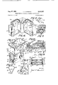
- FIG. 1 is a perspective view of my dry shaver arranged with my individually assembled cushioning shaving units
- FIG. 2 is an exploded view showing the parts of my cushioning shaving unit in separated position
- FIG. 3 is a fragmentary perspective view of a portion of the movable cooperating cutter member
- FIG. 4 is a view of suitably-shaped blank-portions of spring-material before being formed into desired shapes
- FIG. 5 is a cross-sectional view taken along the line 5-5 of FIG. 1, showing the construction of my individually-assembled cushioning shaving unit and also showing the retractable .tensioning position of the elements while the shaving unit is in normal shaving position;
- FIG. 6 is a view similar to that shown in FIG. 5, showing herein the yieldable action of the tensioning elements when the unit is in retractable or transversely movable position relative to its base section;
- FIG. 7 is a perspective view of the carrier for holding the individually-assembled shaving units
- FIG. 8 is a fragmentary perspective view showing a portion of the carrier having snap-fastening means for interlocking with the end portions of the assembled shaving units;
- FIG. 9 is a fragmentary perspective view showing a modified part of the base section and of a portion of the spring structure for holding the individual shaving unit against movements longitudinally of such unit;
- FIG. 11 is a perspective view of the receptacle having the motor secured thereto, showing the removable actuating structure having side portions connectable to the motor shaft, and also showing the structure for starting motor openation;
- FIG. 12 is a side view showing an inner portion of the motor structure for starting motor operation
- FIG. 13 is a view of the spring member for supporting the motor starter
- FIG. 14 is a modified view showing a plurality of individual shaving units and also showing the actuating structure
- FIG. 15 is a view showing the washer for the actuating structure
- FIG. 16 is a perspective view of portions of a handle casing for housing the motor and for serving as a handle for the shearing section;
- FIG. 17 is a perspective view of a modified outer cutter member carrying its movable cooperating cutter member
- FIG. 18 is a perspective view of the separate base section for the outer cutter member shown in FIG. 17;
- FIG. 19 is a perspective view of a modified spring structure
- FIG. 20 is a view of the outer cutter member shown in FIG. 17 and its base section and spring structure in assembled form as a completely-assembled shaving unit;
- FIG. 21 is a fragmentary perspective view of an end portion of the assembled shaving unit shown in FIG. 20;
- FIG. 22 is another fragmentary perspective view of the end portion of the assembled shaving unit shown in FIG. 20;
- FIG. 23 is a view partly in cross-section showing the manner of operation of another modified spring structure.
- FIG. 24 is a view of a blank-portion for a modified spring structure.
- FIG. 2 The parts illustrated in FIG. 2 may be identified generally as the base section A, the outer cutter member B and the reciprocatory cutter C, and removable spring members 1 and 2 associated therewith, for being united into a unitary structure of an assembled shaving unit, as shown in FIGS. 5 and 6.
- the shaving implement comprises a handle-casing E and a shearing-section F.
- the base portion A comprises a floor portion 5 having an opening 6 and two extending end portions 7 and 8; and is also provided with two facing wall portions 11 and 12 each having a hook section 14.
- the outer cutter B comprises a bottom or fioor portion 15 having an opening 16 and two end openings 17 and 18, and is also provided with two side wall portions 21 and 22 each having a flanged section 24.
- a U-shaped member 25, of suitable shape, provided with a shear-face 26 terminating into facing side wall portions 27 is positioned between the wall portions 21 and 22 and secured thereto by suitable means, for example, friction-fit, spotwelding or the kind, in a manner providing a unitary outer cutter structure.
- the reciprocatory cutter C comprises a shearing face 31 terminating into two facing side wall portions 32, having elements or plates 34 and 35, of suitable shape, positioned therebetween and secured thereto in any suitable manner; the elements 34 and 35 are each provided with suitably-shaped openings 37 for receiving and housing therein end portions 38 of the spring member 1.
- These elements 34 and 35 may be formed into any desirable shape; for example, flat-shape, or semi-circular shape cross-sectionally, but for illustrative purposes I am showing the elements 34 and 35 being of somewhat angular shape wherein the wall section 39 (FIG. 3) is provided with the opening 37, thereby facilitating the placing of the end portions 38 of spring member 1 into such openings 37 uniting such spring member 1 with the cutter member C into a unitary structure.
- the spring member 1 is provided with a plurality of bent portions i and i to facilitate the flexibility or resilient action of the tensioning movements of such spring member 1 during shaving operation.
- Such spring member 1 is first stamped out of spring material into a blank-shape S (FIG. 4) having its end portions 38 provided with shoulder-portions 38, and is then formed into desired shape.
- the end portions 38 of the spring member 1 may each be placed into one of the openings 37, of the inner cutter C, in a manner whereby each of the shoulder portions 38' may be located against one of the Wall sections 39 and be held in position by the tensioning action of the spring member 1.
- This form of structure and method of assembling the parts is quite a simple operation so that an unskilled worker can very easily place the spring member 1 into desired position within the openings 37; all one has to do is to place one of the end portions 38 into one of the openings 37 and then flex the spring member 1 a bit and place the other of the end portions 38 into the other of the openings 37, thereby eliminating expensive precisional labor, thus reducing the manufacturing cost of the implement.
- such reciprocatory cutter C When so assembled, such reciprocatory cutter C is then positioned within the outer cutter B, thereby providing a shaving unit with cooperable shearing faces 26 and 31.
- a spring structure 2, shaped or formed of the springblank 5', is provided with a centrally located opening 42 having downwardly extending flange portions 43, and is also provided with suitably shaped end sections 44 each terminating into a hook portion 45 shaped in a manner providing a shoulder structure X.
- This spring structure 2 may be secured into position in the same manner as is the spring member 1; that is, one of the hook portions 45 is positioned within the opening 17 (or 18) and then flexing such spring structure a bit until the other of the hook portions 45 is placed within the opening 18 (or 17); such spring structure 2 will then be tensioned as clearly seen in FIG. 5 and thus be held in desired position.
- the assembled shaving unit that is the outer cutter member B and the reciprocatory cutter member C, including the spring member I and the spring structure 2, after being properly assembled, may be positioned upon the base portion A in a manner wherein the flanged sections 24 are located under the hook sections 14, and having the extending flange portions 43 located within the recessed portions 47 of the floor portion 5, which are held therein by the tension of the spring structure 2, in a manner preventing movements of the said shaving unit longitudinally thereof during shaving operation, thereby providing an assembled shaving unit wherein when the shear-face 26 is pressed against the face being shaved the outer cutter member (including the reciprocatory cutter member) will retract and move transversely thereby cushioning its touch against such face during shaving operation ⁇ see FIGS. 5 and 6).
- the tensioning action of the spring member 1 will hold the shearing face 31 of the rcciprocatory cutter C in frictional engagement with the under face of the shearface 26 of the outer cutter B (FIGS. 5 and 6), and the tensioning action of the spring structure 2 will hold the outer cutter member 8 in a constant upward position with respect to the base portion A, that is, in a position away from such base portion, and will move backward'ly only when placed upon a face for shaving purposes or when pressed against an object.
- the flange portions 43 located within the recessed portions 47 will hold the outer cutter member B against lateral movements thereby preventing side movements of such outer cutter member during the movements of the reciprocatory cutter member.
- cushioning shaving unit may be constructed in any suitable style, form or shape; for example, rotatable style or shape; the disclosures herein are for illustrative purposes only and not for limitation purposes.
- the handle casing E comprises a body-portion 52 and a cover section 53, each of hollow structure to house a motor therein.
- Such casing is provided with inwardly extending rib portions 54 and with an upwardly or top box or seat structure 55 having an outer head 56 provided with an inner groove 57 (FIGS. and 16).
- the motor structure is of such a type that it is not provided with means for holding such wheel; the wheel is usually held by the handle casing, and is supported in its position by small spring structures; such wheel and spring structures are positioned at the interior of the handle casing while such casing is being closed, and must be so arranged whereby the wheel is kept away from the motor by the tension of such spring structures; it is only by outer pressure against the wheel that such wheel engages the motor for operable purposes.
- the starting wheel 73 is carried directly by the motor and not by the casing section, for example, my motor 65 is provided with two wall portions 66 each having an opening or slot 67 wherein is placed the loop-portions 68 of a spring structure R.
- the free end portions 69 are inclined towards each other and each terminated into a loop or ring portion 71, for housing therein the shoulder portions 72 of the starting wheel 73.
- the two facing wall portions 77 and 77' may each be provided with a slot 78 for receiving therein washers 79 carrying an actuating set 81, and have closure elements 82 secured thereto in a manner closing the slot 78 and holding the actuating set 81 in desired position.
- the motor '65 and the receptacle 61 are secured to each other by suitable means; for example, welding process, screws or rivets 76, and form thereof a unitary assembled structure indicated by arrow T including motor starting means.
- the actuating set or element 81 is provided with two downwardly extending portions 83 each terminating into a forked end section 84 for co-operating with an eccentric member 85 which is secured to a rotatable motor shaft 86 (FIGS. 11 and 14).
- the forked end sections 84 are in proper alignment with each other and so are the two eccentric members 85 in proper alignment with each other; thus, both end portions of the rotatable shaft 86 are in a position to operate the actuating set 81 thereby greatly reducing the strain-exertion of the motor 65 for operating the shearing section F, and also prolonging the life of the motor and the usefulness of the shaving imptefanent.
- such unitary structure T When thus assembled, such unitary structure T may be positioned slidably within the handle casing E in a manner whereby the rib portions 54 will become located within the spaced sections 54' (FIG. ti) and the flange portions 63 will become located within the groove 57 as clearly shown at 56', FIG. 10, and then placed fully into the casing E. It is quite apparent that such arrangement of structure will hold the unitary structure T firmly in its position without the use of screw-threaded elements; thus further reducing the manufacturing cost of this type of shaving implements.
- the cover 53 When the structure T is fully inserted into its position the cover 53 may be placed over it and secured to the d casing 52 by means of screw-members 52 secured within screw-threaded openings 52'', or by other suitable means, :for example, spring elements (not shown), thereby completing the handle structure E in a manner adaptable for use in connection with a shearing section for shaving purposes.
- I provide a sheet-metal stamping 91 having a centrally located opening 91.
- the two end portions 92 are each bent or curved inwardly as at 92 terminating into a loop portion 93 located closely to the floor 93' of the stamping 91, as shown at 93" (FIGS. '7 and 8), and then bent backwardly as shown at 94 and curved outwardly as at 94' terminating into a flange portion 95.
- Each of the iloor portions 93 are provided with openings or recessed sections 96 which are covered by the loop portions 93, for a purpose which will be hereinafter explained.
- the extending end portions 7 and 8, of the floor portion of the base portion A are each provided with downwardly pressed tent or snap portions 9; such snap portions are in proper alignment with the recessed sections 96 of carrier M for the following reason:
- My assembled shaving units are not secured to the carrier by means of screw-elements or the like as is the practice with the present type of electric shaving structures; in my present invention I slide my assembled shaving unit sideways within the spaced sections 10, between the floor 93 and the loop portion 93, until the snap portion 9 snaps into the recessed sections 96 of the floor portions 93 and become thus interlocked in its position upon the carrier M.
- the spring tension of the llOOP portion 93 will facilitate such slidable side movement and also hold the shaving unit secured in its position.
- the carrier (holding the shaving units) is then placed within the receptacle 6! (FIGS. 5, 6, 10 and 14) in a manner whereby the units may be located between the wall portions 77 and 77' (see FIG. 14), and the flange portions 95 are then pressed over the outer bead portions 56, of the top or sent structure 55, in a manner whereby the curved portions 94' may snap into position under such bead portions 56 and engage frictionally the underface thereof as shown by numeral 97 (FIGS. 5, 6 and 10); thereby securing the assembled shearing section F to the handle structure. Moving the flange portions 95 out of their position will release the hold of the curved portions 94' and the shearing section may thus be removed from the handle structure.
- the shearing or shaving units may be so constructed as to be of square-shape cross-sectionally, as shown in FIG. 2; or they may be of semi-circular shape, as shown in FIG. 14; or of any other suitable shape; or the recessed portions 47 of the floor portion 5 may be eliminated and the side floor portions 5a (see FIG. 9) may be provided with upwardly raised portions 5' (further indicated by the dotted lines 5"); and the flap portions 43 of the spring member 2 may be eliminated, and the side wall portions 4 of such spring member 2 may each be provided with an upwardly projecting bent section 4' adapted to fit over the raised portion 5'.
- the means for holding the outer unit in connection with the base portion may be of a structure other than that of the hook sections 14 and the flanged sections 24.
- Various forms of structure may be resorted to without departing from the spirit of this invention.
- My assembled cutter unit which comprises of a base portion and an outer cutter member having a reciprocatory cutter member and spring structures 1 and 2, is so arranged that when held by hand (without the handle structure) it can easily be noted that the outer cutter member is movable transversely with respect to the base portion, that is, one can press the outer cutter member towards the base portion and feel (and also see) the automatic adjustable movements of the outer cutter member with respect to the base portion.
- the spring member 2 may be eliminated and the spring member I may be made of such a curved shape, or be concaved to such a degree, whereby it will provide tension action for holding the shearing face of the reciprocatory cutter member in frictional engagement with the shearing face of the outer cutter member and simultaneously therewith also provide tensioning action to hold the outer cutter member in a position spaced away from the base portion for yieldable or retractable purposes.
- the assembled shaving unit which usually comprises only an outer cutter member and a reciprocatory cutter member is, in this case, provided with an additional member serving as a base portion, which is so arranged, that while carrying such shaving unit (of two cutter members) it also permits yieldable movements of such shaving unit with respect to such base portion; and such base portion (not the outer cutter memher) is provided with the means for being secured to a carrier or directly to a handle structure.
- cover element or structure N is then positioned over such shearing section F covering the side portions thereof leaving the shearing face 26 exposed for shaving purposes.
- cover element may be secured to the handle-casing 52 by various suitable means; for example, friction fit as shown at V (FIG. 5), or by snap-fastening means as indicated by numeral 99 (dotted lines, FIG. 5), or by other suitable means.
- cover N may be provided with flange portions 99 for overlapping the end portions of the shearing faces 26 of the shaving units (FIGS. 1-5 and 6) for controlling the upward movement of the outer shearing member B or for other purposes.
- the closure elements 82 may each be provided with a rear member 82 secured to its back-face by suitable means, for example, welding process or rivets 78', for holding the closure elements 82 in desired location; or the top box structure 55 (FIG. 16) may be provided with extending portions 570 for overlying the closure elements 82 to prevent accidental displacement of such closure elements 82.
- the units :18 may be carried by a carrier 152 and held in position by screw-members tin and supported by a spring structure d which is secured to a portion (13 of the carrier 152 by means of a screw ele ment d4.
- the spring structure d may be provided with a centrally located opening d1 and with a plurality of end portions d2 (FIG. 24).
- Each of the end portions d2 may be provided with a curved portion d9 terminating into an upwardly extending section d5 (FIG.
- the structure of my cushioning shaving unit may be so arranged whereby the spring section may be located underneath the separate base section of such shaving unit for providing suitable tensioning means to urge such shaving unit into movements transversely relative to such separate base section.
- the floor portion 15 of the outer cutter member B is provided with openings 17 and 18 and with a centrally located opening 16.
- the material of the openings 17 and 18 provide suitably-shaped flange portions b1 (FIG. 17) each having a neck section b forming shoulder portions b2 and terminating into extending portions b4 shaped into a triangular section.
- the base section A is provided with side openings a9 and with a centrally located opening a7; the material of the opening a7 form flange portions a8.
- This type of structure may be assembled in the following manner: The triangular-shaped portions of the outer cutter member B are each placed through one of the openings a9 and through one of the triangular-shaped openings a4 (see FIG. 21) until the shoulder portions b2 rest against one of the faces of the spring member a1, as indicated by the dotted lines 157, the extending portions 174 are then placed in a straight position over the other face of the spring member a1, thus securing the outer cutter member B to the spring member 01, see FIG. 22.
- the end portions 013 of the spring a1 will urge the outer cutter member towards an upward position, that is, into a position away from the base section, as shown in FIG. 20; but when placed against a face being shaved such end portions 03 will yield and permit transverse movements relative to the base section A as indicated by numerals c2 and 03, FIG. 20.
- the movable cooperating cutter C is carried by the outer cutter member B and operated in its position by suitable actuating means as indicated by dotted lines d7 (FIGS. 17 and 23).
- each of the handle casing sections 52 and 53 with a recessed or cut-out portion 52a for having the opening 75 housing the starting Wheel 73 at a certain location, yet, such opening 75 may be shaped or formed in any other suitable manner, and be located at any other suitable place of the handle structure.
- a shaver comprising a handle casing having a seat portion, said seat portion carrying thereon a removable base section, said base section carrying a removable spring member and a removable shaving unit, said shaving unit comprising an outer cutter member having a shear face and a bottom portion located opposite said shear face and a movable cooperating cutter member, said spring member having a center portion and a pair of spaced resilient end sections, said shaving unit movable transversely relative to the said base section, holding means on the said spring, said resilient end sections engageable with spaced parts of the said bottom portion of said outer cutter member and the said center portion of said spring member held in position to the said base section by the said holding means for preventing movements of such outer cutter member longitudinally of such base section, said resilient end sections exerting spring pressure against the said bottom portion for urging said outer cutter member into the said transverse movements during shaving operation, the said base section and said spring member and said shaving unit adapted to be assembled into a unitary structure positionable upon the said seat as such assembled unitary structure and be removed from the said
- a shaver comprising a handle casing provided with a seat portion for having a removable assembled shearing section secured thereto, said shearing section comprising a separate removable base section and a spring member and at least one shaving unit, said shaving unit comprising an outer cutter member having a floor portion and having a cooperating movable cutter member, the said shaving unit movable transversely relative to the said base section, the outer face of said floor provided with a plurality of spaced recessed sections, the said spring member having a center section and two resilient end portions each engageable in an interlocked manner with one of the said recess-ed sections, the center portion of said spring member connectable with a portion of the said base section for urging the said resilient end portions to press against the said floor to intice the said shaving unit into transverse movements during shaving operation, said base section and the said spring member and the said shaving unit adapted to be assembled into a unitary structure positionable upon the said seat portion as an assembled unitary structure and be removed from such seat as such assembled unitary structure.
- a shaver comprising a handle casing provided with a seat portion having secured thereto an assembled removable shearing structure.
- said shearing structure comprising a separate base section having a centrally located opening provided with recessed portions, and a spring member having centrally located flange portions and resilient end sections, each of said end sections provided with shoulder portions, and a shaving unit consisting of an outer cutter member having an under face provided with spaced end openings and having a movable cooperating cutter member, said shaving unit caried loosely by the said base section and being movable transversely relative to said base section, the end portions of the said resilient end sections of the said spring member each positionable within one of the said openings of the said outer cutter member having its shoulder portion resting against the under face of said outer cutter member and having its centrally located flange portions located within the said recessed portions of said base section for preventing longitudinal movements of the said outer cutter member during shaving operation, said resilient end sections providing spring tension for urging the said transverse movements, means for limiting the distance of the said transverse
- a shaver comprising a handle casing provided with a seat portion for supporting thereon a removable assembled shearing section, said shearing section comprising a separate removable base section having centrally located raised portions, and a spring member having upwardly extending end portions and centrally located upwardly projecting sections, and a shaving unit consisting of an outer cutter member having associated therewith a movable cooperating cutter member, said outer cutter member carried loosely by the said separate base section and provided with retention means for being held in position thereon and permitting transverse movements of such outer cutter member relative to the said base section, said end portions of the said spring member connectable with the said outer cutter member and having its said projecting sections positionable over the said raised portions for holding such outer cutter member in desired position upon the said base section, said base section and the said spring member and the said outer cutter member united into a unitary structure positionable upon the said seat portion as an assembled shearing section and removable from such seat portion as an assembled shearing section, the said spring member being removable from the said outer cutter member and from the said base section to
- a shaver comprising a handle casing having a seat portion provided With a removable shearing structure, said shearing structure comprising a se arate base section having an under face and spaced end openings and a spring member having a centrally located section provided with resilient end portions, and a shaving unit, said shaving unit consisting of an outer cutter member having flange portions and provided with a removable coopcrating cutter member, the centrally located section of the said spring member secured to the said under face of the said base section, said flange portions of the said outer cutter member each positioned through one of said end openings of the said base section and fastened to one of said resilient end portions of the said spring member, said end portions providing resilient tension for urging the said outer cutter members into movements transversely relative the said base section, portions of said under face serving as retention means for holding said outer cutter member is desired position, said separate base section and the said spring member and the said outer cutter member united into a unitary structure positionable upon the said seat portion and secured thereto as an assembled unitary shearing structure
Landscapes
- Life Sciences & Earth Sciences (AREA)
- Forests & Forestry (AREA)
- Engineering & Computer Science (AREA)
- Mechanical Engineering (AREA)
- Dry Shavers And Clippers (AREA)
Description
27, 1963 J. L. KLEINMAN 3,101,537
SHAVER HAVING A REMOVABLE ASSEMBLED SHAVING UNIT Filed Feb. 27, 1961 3 Sheets-Sheet 1 Zfdff fizZLZQ-ff- Aug. 27, 1963 J. L. KLEINMAN SHAVER HAVING A REMOVABLE ASSEMBLED SHAVING UNIT Filed Feb. 27, 1961 3 Sheets-Sheet 2 INVENTOR.
Aug. 27, 1963 J. L. KLEINMAN 3,101,537
SHAVER HAVING A REMOVABLE ASSEMBLED SHAVING UNIT Filed Feb. 27, 1961 3 Sheets-Sheet 3 B or: n-I v I 4 UV. C
L I A,
United States Patent 3,101,537 SHAVER HAVING A REMOVABLE ASSEMBLED SHAVING UNIT Jacob L. Kleinman, Hotel Kimberly, 74th St. at Broadway, New York, N.Y. Filed Feb. 27, 1961, Ser. No. 115,275 5 Claims. (Cl. 30-43) This invention relates to the construction of dry shavers in general, and more particularly to a type of structure provided with an assembled shaving unit carried by a separate base section and being movable transversely relative to such base section, and wherein such base section is positionable upon a seat of a handle portion of a dry shaving implement as a completely-assembled unitary shaving unit and removable from such handle portion as such completely-assembled shaving unit; and wherein the motor is carried by a receptacle having a non punctured floor; and wherein the said receptacle is provided with a removable actuating set having portions thereof connectable with each of the end portions of the rotatable motor shaft for reducing operable strain of the motor during shaving operation; and wherein the motor structure is provided with a rotatable motor starter; and wherein the motor structure in combination with its receptacle is positionable within the handle section slidably as a unitary structure and held therein by friction fit without the aid of screw threaded elements.
This application is filed as a continuation in part of my copending application S.N. 858,088, for Cushioning Shaving Head Units for Shaving Implements, filed December 8, 1959, now Patent Number 2,979,819, granted April 18, 1961.
A primary object of the present invention is to provide an improved shaving implement which is practical for shaving purposes and capable of being manufactured at a low cost.
An important object of this invention is the provision of an assembled shaving unit comprising an outer cutter member having a cooperating movable cutter member and also having a separate base section, wherein the said outer cutter member is carried by the base section in a loose manner, that is, in a manner whereby such outer cutter member is movable freely Within its position, particularly so, transversely relative to its base section (to and from such base section), enabling the shearface of the shaving unit to cushion its touch against the face being shaved.
Another important object of this invention is the provision of a spring structure (for supporting the abovementioned outer cutter member in its transverse movements) which may he placed into position and be held in such position without the use of screw-threaded elements or the kind, and which may be readily removable for cleaning or replacement purposes.
A rfurther important object of this invention is to provide an improved shearing section consisting of a plurality of individually assembled shaving units each having a separate base section, wherein the said base sections are each secured slidably into position upon a carrier and wherein the said carrier is secured to a handle structure of a shaving implement, and wherein each of the shaving units may be movable or tiltable transversely into various degrees with respect to its respective base section for individual automatic adjustment of position of each of such individual units during shaving operation.
For clarification purposes I wish to point out the following:
The ordinary type of individually removable shaving units, for use in connection with dry shavers or electric 3 ,101,537. Patented Aug. 27, 1963 razors, consist of only two members, an outer cutter member and a cooperating cutter member; the outer cutter member is secured to a handle in a rigid non-movable manner, and can therefore not move in either direction, certainly not in a transverse manner ior automatic adjustment to the curvatures of face being shaved, and in many instances the fine shearing teeth of such outer cutter member scratch the tender skin of such face during shaving operation.
Whereas, in accordance with my present invention, my individually assembled shaving unit consists of an outer cutter member and a cooperating movable cutter memher and a separate base section and a removable spring structure, all assembled into an individually-assembled unitary shaving unit, constructed in a manner wherein the outer cutter member is carried loosely by the base section and is movable transversely relative to such base section and is thus in a position to yield or be tilted to various degrees tor automatic adjustment to the curvatures of the face being shaved.
My present structure is provided with a non-punctured receptacle for housing sheared hair while shaving, thus preventing their entrance into the motor chamber and clogging up the motor located therein. Such receptacle is carrying a removable actuating structure provided with two side sections for engaging the two end portions of the motor shaft to reduce motor strain during shaving operation.
An important feature of my present invention is the provision of the shaving unit with means whereby it may be placed slidably into position upon a carrier and be locked therein without the use of screw members, and wherein such combined carrier and shaving unit may then be secured into position upon a handle structure without the use of screw-members or the kind.
To illustrate the ordinary commercial utility of my improved shaving implement (provided with a plurality of my cushioning shaving units) in daily life, such shaving implement made in accordance with my invention, of whatever type or style it may be made, could be utilized to great advantage; the fact that in my shaving implement each of the individual shaving units is tiltable into various directions, will enable the shear-faces of such. individual shaving units to adjust themselves automatically into various degrees with respect to the face being shaved, and thus render a clean and fast shave, provide gentle contact with face while shaving, and minimize breakage possibilities of the fine shearing teeth while shaving.
Furthermore, the fact that in my shaving implement the actuating structure can be easily removable and/0r replaceable, or adjustable, will greatly reduce the cost of the implement and its upkeep.
Thus, an individually-assembled shaving unit for a dry shaver, of whatever style or type it may be made, produced in accordance with my invention, fulfills a longfelt need in the electric razor industry. My herein invention teaches a new and unique form of structure and solves the most vexing problems in the art of making individually-assembled shaving units for electrically operated dry shavers. My invention disclosed herein is a practical and useful structure and can be utilized to great advantage in connection with the manufacturing of dry shavers.
The objects of my invention are attained by a novel construction which will be hereinafter described and illustrated in the drawing in connection with a specific embodiment of the invention.
In the accompanying drawing in which such specific embodiment of my invention is illustrated, and described in the annexed specification, wherein the accomplishment of the above and other objects of the invention will be readily understood on reference to the herein wherein:
FIG. 1 is a perspective view of my dry shaver arranged with my individually assembled cushioning shaving units;
FIG. 2 is an exploded view showing the parts of my cushioning shaving unit in separated position;
FIG. 3 is a fragmentary perspective view of a portion of the movable cooperating cutter member;
FIG. 4 is a view of suitably-shaped blank-portions of spring-material before being formed into desired shapes;
FIG. 5 is a cross-sectional view taken along the line 5-5 of FIG. 1, showing the construction of my individually-assembled cushioning shaving unit and also showing the retractable .tensioning position of the elements while the shaving unit is in normal shaving position;
FIG. 6 is a view similar to that shown in FIG. 5, showing herein the yieldable action of the tensioning elements when the unit is in retractable or transversely movable position relative to its base section;
FIG. 7 is a perspective view of the carrier for holding the individually-assembled shaving units;
FIG. 8 is a fragmentary perspective view showing a portion of the carrier having snap-fastening means for interlocking with the end portions of the assembled shaving units;
FIG. 9 is a fragmentary perspective view showing a modified part of the base section and of a portion of the spring structure for holding the individual shaving unit against movements longitudinally of such unit;
FIG. 10 is a view partly broken away showing the position of the receptacle within the casing and also showing the slidable manner in which the shaving unit is placed into position upon the carrier;
\FIG. 11 is a perspective view of the receptacle having the motor secured thereto, showing the removable actuating structure having side portions connectable to the motor shaft, and also showing the structure for starting motor openation;
FIG. 12 is a side view showing an inner portion of the motor structure for starting motor operation;
FIG. 13 is a view of the spring member for supporting the motor starter;
FIG. 14 is a modified view showing a plurality of individual shaving units and also showing the actuating structure;
FIG. 15 is a view showing the washer for the actuating structure;
FIG. 16 is a perspective view of portions of a handle casing for housing the motor and for serving as a handle for the shearing section;
FIG. 17 is a perspective view of a modified outer cutter member carrying its movable cooperating cutter member;
FIG. 18 is a perspective view of the separate base section for the outer cutter member shown in FIG. 17;
FIG. 19 is a perspective view of a modified spring structure;
FIG. 20 is a view of the outer cutter member shown in FIG. 17 and its base section and spring structure in assembled form as a completely-assembled shaving unit;
FIG. 21 is a fragmentary perspective view of an end portion of the assembled shaving unit shown in FIG. 20;
FIG. 22 is another fragmentary perspective view of the end portion of the assembled shaving unit shown in FIG. 20;
FIG. 23 is a view partly in cross-section showing the manner of operation of another modified spring structure; and
FIG. 24 is a view of a blank-portion for a modified spring structure.
I am showing the several views or figures by way of example for illustrative purposes and for a better and clearer understanding of my invention, and not for limitation purposes.
Referring more particularly to the drawing, in which similar reference characters identify similar parts in the several views, in the novel structure of my invention.
The parts illustrated in FIG. 2 may be identified generally as the base section A, the outer cutter member B and the reciprocatory cutter C, and removable spring members 1 and 2 associated therewith, for being united into a unitary structure of an assembled shaving unit, as shown in FIGS. 5 and 6.
The shaving implement comprises a handle-casing E and a shearing-section F.
The base portion A comprises a floor portion 5 having an opening 6 and two extending end portions 7 and 8; and is also provided with two facing wall portions 11 and 12 each having a hook section 14.
The outer cutter B comprises a bottom or fioor portion 15 having an opening 16 and two end openings 17 and 18, and is also provided with two side wall portions 21 and 22 each having a flanged section 24. A U-shaped member 25, of suitable shape, provided with a shear-face 26 terminating into facing side wall portions 27 is positioned between the wall portions 21 and 22 and secured thereto by suitable means, for example, friction-fit, spotwelding or the kind, in a manner providing a unitary outer cutter structure.
The reciprocatory cutter C comprises a shearing face 31 terminating into two facing side wall portions 32, having elements or plates 34 and 35, of suitable shape, positioned therebetween and secured thereto in any suitable manner; the elements 34 and 35 are each provided with suitably-shaped openings 37 for receiving and housing therein end portions 38 of the spring member 1. These elements 34 and 35 may be formed into any desirable shape; for example, flat-shape, or semi-circular shape cross-sectionally, but for illustrative purposes I am showing the elements 34 and 35 being of somewhat angular shape wherein the wall section 39 (FIG. 3) is provided with the opening 37, thereby facilitating the placing of the end portions 38 of spring member 1 into such openings 37 uniting such spring member 1 with the cutter member C into a unitary structure.
The spring member 1 is provided with a plurality of bent portions i and i to facilitate the flexibility or resilient action of the tensioning movements of such spring member 1 during shaving operation. Such spring member 1 is first stamped out of spring material into a blank-shape S (FIG. 4) having its end portions 38 provided with shoulder-portions 38, and is then formed into desired shape.
In the course of assembling my shaving unit the following method may be followed: The end portions 38 of the spring member 1 may each be placed into one of the openings 37, of the inner cutter C, in a manner whereby each of the shoulder portions 38' may be located against one of the Wall sections 39 and be held in position by the tensioning action of the spring member 1. This form of structure and method of assembling the parts is quite a simple operation so that an unskilled worker can very easily place the spring member 1 into desired position within the openings 37; all one has to do is to place one of the end portions 38 into one of the openings 37 and then flex the spring member 1 a bit and place the other of the end portions 38 into the other of the openings 37, thereby eliminating expensive precisional labor, thus reducing the manufacturing cost of the implement.
When so assembled, such reciprocatory cutter C is then positioned within the outer cutter B, thereby providing a shaving unit with cooperable shearing faces 26 and 31.
A spring structure 2, shaped or formed of the springblank 5', is provided with a centrally located opening 42 having downwardly extending flange portions 43, and is also provided with suitably shaped end sections 44 each terminating into a hook portion 45 shaped in a manner providing a shoulder structure X. This spring structure 2 may be secured into position in the same manner as is the spring member 1; that is, one of the hook portions 45 is positioned within the opening 17 (or 18) and then flexing such spring structure a bit until the other of the hook portions 45 is placed within the opening 18 (or 17); such spring structure 2 will then be tensioned as clearly seen in FIG. 5 and thus be held in desired position.
For clarification purposes applicant is showing space between certain of the parts or members, whereas, in reality, there is no space therebetween', the same is true with respect to size of the parts.
The assembled shaving unit, that is the outer cutter member B and the reciprocatory cutter member C, including the spring member I and the spring structure 2, after being properly assembled, may be positioned upon the base portion A in a manner wherein the flanged sections 24 are located under the hook sections 14, and having the extending flange portions 43 located within the recessed portions 47 of the floor portion 5, which are held therein by the tension of the spring structure 2, in a manner preventing movements of the said shaving unit longitudinally thereof during shaving operation, thereby providing an assembled shaving unit wherein when the shear-face 26 is pressed against the face being shaved the outer cutter member (including the reciprocatory cutter member) will retract and move transversely thereby cushioning its touch against such face during shaving operation {see FIGS. 5 and 6).
The tensioning action of the spring member 1 will hold the shearing face 31 of the rcciprocatory cutter C in frictional engagement with the under face of the shearface 26 of the outer cutter B (FIGS. 5 and 6), and the tensioning action of the spring structure 2 will hold the outer cutter member 8 in a constant upward position with respect to the base portion A, that is, in a position away from such base portion, and will move backward'ly only when placed upon a face for shaving purposes or when pressed against an object. The flange portions 43 located within the recessed portions 47 will hold the outer cutter member B against lateral movements thereby preventing side movements of such outer cutter member during the movements of the reciprocatory cutter member.
When my shaving unit is thus fully assembled it will be found that the openings 16 of the outer cutter B and the opening 42 of the spring structure 2 and the opening 6 of the base portion A are all located in proper alignment for having an actuating member 49 pass therethrough to have its head portion 50 nest itself into a recessed or bent portion 51 of the spring member 1 for moving the reciprocatory cutter member C for shaving purposes.
I desire it to be clearly understood that my cushioning shaving unit may be constructed in any suitable style, form or shape; for example, rotatable style or shape; the disclosures herein are for illustrative purposes only and not for limitation purposes.
The handle casing E comprises a body-portion 52 and a cover section 53, each of hollow structure to house a motor therein. Such casing is provided with inwardly extending rib portions 54 and with an upwardly or top box or seat structure 55 having an outer head 56 provided with an inner groove 57 (FIGS. and 16).
A receptacle 61 having a non-punctured floor 62, is provided with outwardly formed flange portions 63 and with flap sections 64 (FIGS. 10 and 11) for holding secured thereto a motor 65, forming a unitary structure of such receptacle and motor.
In connection with the motor structure applicant desires to point out the following;
In the ordinary type of shavers, wherein the motorstarter consists of a rotatable wheel, the motor structure is of such a type that it is not provided with means for holding such wheel; the wheel is usually held by the handle casing, and is supported in its position by small spring structures; such wheel and spring structures are positioned at the interior of the handle casing while such casing is being closed, and must be so arranged whereby the wheel is kept away from the motor by the tension of such spring structures; it is only by outer pressure against the wheel that such wheel engages the motor for operable purposes. It is quite clear that to place such wheel and spring structures at the interior of the handle casing While closing such casing, particularly so when such wheel is movable in its position and has to be supported by both sections of such casing, requires precisional manipulation, skilled workmanship, and ample time; such wheel is situated loosely in its position so as to move freely therein, and while closing such casing, the wheel and/or the spring structures may easily get out of their respective positions. This form of adiustment can not be controlled, it is skilled precisional manipulation that is required to adjust the wheel and the spring structures into proper position while closing the handle casing.
Whereas, in my structure the starting wheel 73 is carried directly by the motor and not by the casing section, for example, my motor 65 is provided with two wall portions 66 each having an opening or slot 67 wherein is placed the loop-portions 68 of a spring structure R. The free end portions 69 are inclined towards each other and each terminated into a loop or ring portion 71, for housing therein the shoulder portions 72 of the starting wheel 73. When it is desired to start motor operation, all one has to do is to press the starting wheel 73 towards the motor wheel 74 (as indicated by the dotted lines L, FIG. 12) and make a fast rotatable movement thereof wherein the frictional engagement between the starting wheel 73 and the motor wheel 74 will cause operable action of the motor 65. The spring-tcnsioning action of the free end portions 69, of the spring structure R, will hold the stark ing wheel 73 in a position away from the motor wheel 74 having a portion of such Wheel 73 extending through the opening 75 of the casing E for operable purposes.
It can readily be seen that this particular form of structure will greatly facilitate the assembling operation thus eliminating costly labor operation.
The two facing wall portions 77 and 77' (FIG. 11) may each be provided with a slot 78 for receiving therein washers 79 carrying an actuating set 81, and have closure elements 82 secured thereto in a manner closing the slot 78 and holding the actuating set 81 in desired position.
The motor '65 and the receptacle 61 are secured to each other by suitable means; for example, welding process, screws or rivets 76, and form thereof a unitary assembled structure indicated by arrow T including motor starting means.
The actuating set or element 81 is provided with two downwardly extending portions 83 each terminating into a forked end section 84 for co-operating with an eccentric member 85 which is secured to a rotatable motor shaft 86 (FIGS. 11 and 14). The forked end sections 84 are in proper alignment with each other and so are the two eccentric members 85 in proper alignment with each other; thus, both end portions of the rotatable shaft 86 are in a position to operate the actuating set 81 thereby greatly reducing the strain-exertion of the motor 65 for operating the shearing section F, and also prolonging the life of the motor and the usefulness of the shaving implernent.
When thus assembled, such unitary structure T may be positioned slidably within the handle casing E in a manner whereby the rib portions 54 will become located within the spaced sections 54' (FIG. ti) and the flange portions 63 will become located within the groove 57 as clearly shown at 56', FIG. 10, and then placed fully into the casing E. It is quite apparent that such arrangement of structure will hold the unitary structure T firmly in its position without the use of screw-threaded elements; thus further reducing the manufacturing cost of this type of shaving implements.
When the structure T is fully inserted into its position the cover 53 may be placed over it and secured to the d casing 52 by means of screw-members 52 secured within screw-threaded openings 52'', or by other suitable means, :for example, spring elements (not shown), thereby completing the handle structure E in a manner adaptable for use in connection with a shearing section for shaving purposes.
For practical purposes I provide a carrier M (FIG. 7) for having my units secured thereto and then Securing such carrier to the box or seat-structure 55. I construct my carrier M in the following manner:
I provide a sheet-metal stamping 91 having a centrally located opening 91. The two end portions 92 are each bent or curved inwardly as at 92 terminating into a loop portion 93 located closely to the floor 93' of the stamping 91, as shown at 93" (FIGS. '7 and 8), and then bent backwardly as shown at 94 and curved outwardly as at 94' terminating into a flange portion 95. Each of the iloor portions 93 are provided with openings or recessed sections 96 which are covered by the loop portions 93, for a purpose which will be hereinafter explained.
The extending end portions 7 and 8, of the floor portion of the base portion A (FIG. 2), are each provided with downwardly pressed tent or snap portions 9; such snap portions are in proper alignment with the recessed sections 96 of carrier M for the following reason:
My assembled shaving units are not secured to the carrier by means of screw-elements or the like as is the practice with the present type of electric shaving structures; in my present invention I slide my assembled shaving unit sideways within the spaced sections 10, between the floor 93 and the loop portion 93, until the snap portion 9 snaps into the recessed sections 96 of the floor portions 93 and become thus interlocked in its position upon the carrier M. The spring tension of the llOOP portion 93 will facilitate such slidable side movement and also hold the shaving unit secured in its position.
When so assembled, the carrier (holding the shaving units) is then placed within the receptacle 6! (FIGS. 5, 6, 10 and 14) in a manner whereby the units may be located between the wall portions 77 and 77' (see FIG. 14), and the flange portions 95 are then pressed over the outer bead portions 56, of the top or sent structure 55, in a manner whereby the curved portions 94' may snap into position under such bead portions 56 and engage frictionally the underface thereof as shown by numeral 97 (FIGS. 5, 6 and 10); thereby securing the assembled shearing section F to the handle structure. Moving the flange portions 95 out of their position will release the hold of the curved portions 94' and the shearing section may thus be removed from the handle structure.
As above stated, the disclosures herein are shown by way of example and not for limitation purposes; for example, the shearing or shaving units may be so constructed as to be of square-shape cross-sectionally, as shown in FIG. 2; or they may be of semi-circular shape, as shown in FIG. 14; or of any other suitable shape; or the recessed portions 47 of the floor portion 5 may be eliminated and the side floor portions 5a (see FIG. 9) may be provided with upwardly raised portions 5' (further indicated by the dotted lines 5"); and the flap portions 43 of the spring member 2 may be eliminated, and the side wall portions 4 of such spring member 2 may each be provided with an upwardly projecting bent section 4' adapted to fit over the raised portion 5'. So that when properly assembled, such structure will permit tensioning action, or retractable movements, of the shaving units in cooperation with the spring member 2, with respect to the base portion A, but will prevent displacement of such unit from its position. Or the means for holding the outer unit in connection with the base portion may be of a structure other than that of the hook sections 14 and the flanged sections 24. Various forms of structure may be resorted to without departing from the spirit of this invention.
I desire to point out the following: My assembled cutter unit, which comprises of a base portion and an outer cutter member having a reciprocatory cutter member and spring structures 1 and 2, is so arranged that when held by hand (without the handle structure) it can easily be noted that the outer cutter member is movable transversely with respect to the base portion, that is, one can press the outer cutter member towards the base portion and feel (and also see) the automatic adjustable movements of the outer cutter member with respect to the base portion. This form of structure is preferable; but if desired, the spring member 2 may be eliminated and the spring member I may be made of such a curved shape, or be concaved to such a degree, whereby it will provide tension action for holding the shearing face of the reciprocatory cutter member in frictional engagement with the shearing face of the outer cutter member and simultaneously therewith also provide tensioning action to hold the outer cutter member in a position spaced away from the base portion for yieldable or retractable purposes. It is the fact that the assembled shaving unit which usually comprises only an outer cutter member and a reciprocatory cutter member is, in this case, provided with an additional member serving as a base portion, which is so arranged, that while carrying such shaving unit (of two cutter members) it also permits yieldable movements of such shaving unit with respect to such base portion; and such base portion (not the outer cutter memher) is provided with the means for being secured to a carrier or directly to a handle structure.
When the assembled shearing section F is secured into position upon the handle structure, a cover element or structure N is then positioned over such shearing section F covering the side portions thereof leaving the shearing face 26 exposed for shaving purposes. Such cover element may be secured to the handle-casing 52 by various suitable means; for example, friction fit as shown at V (FIG. 5), or by snap-fastening means as indicated by numeral 99 (dotted lines, FIG. 5), or by other suitable means. Such cover N may be provided with flange portions 99 for overlapping the end portions of the shearing faces 26 of the shaving units (FIGS. 1-5 and 6) for controlling the upward movement of the outer shearing member B or for other purposes.
As above stated, the disclosures herein are for illustrative purposes only and not for limitation purposes. For example, if desired, the closure elements 82 (FIG. 11) may each be provided with a rear member 82 secured to its back-face by suitable means, for example, welding process or rivets 78', for holding the closure elements 82 in desired location; or the top box structure 55 (FIG. 16) may be provided with extending portions 570 for overlying the closure elements 82 to prevent accidental displacement of such closure elements 82.
If desired, the units :18 (FIG. 23) may be carried by a carrier 152 and held in position by screw-members tin and supported by a spring structure d which is secured to a portion (13 of the carrier 152 by means of a screw ele ment d4. In this form of structure the spring structure d may be provided with a centrally located opening d1 and with a plurality of end portions d2 (FIG. 24). Each of the end portions d2 may be provided with a curved portion d9 terminating into an upwardly extending section d5 (FIG. 23) for being located into a grooved or recessed portion d6 of the under section of the unit (18 to support and urge the units d8 towards an upward position and to provide tensioning means enabling such units d3 to retract automatically while pressed against a face being shaved thereby cushioning the touch of the shear-faces of the units d8 against the face during shaving operation.
If desired, the structure of my cushioning shaving unit may be so arranged whereby the spring section may be located underneath the separate base section of such shaving unit for providing suitable tensioning means to urge such shaving unit into movements transversely relative to such separate base section.
The floor portion 15 of the outer cutter member B is provided with openings 17 and 18 and with a centrally located opening 16. The material of the openings 17 and 18 provide suitably-shaped flange portions b1 (FIG. 17) each having a neck section b forming shoulder portions b2 and terminating into extending portions b4 shaped into a triangular section.
The base section A is provided with side openings a9 and with a centrally located opening a7; the material of the opening a7 form flange portions a8.
The spring member a1 (FIG. 19) is provided with a centrally located opening a6 and with curved side portions 02 each terminating into an end portion a3 provided with a triangular-shaped slot (14 having angularly-disposed slot portions a5.
The spring member a1 is placed against the underface of the base section A having its opening a6 fitting over the flange portions a8 (FIG. 20), such end portions are then bent or turned over the portions of material indicated by numeral all of the spring a1 (FIG. 19) as clearly shown at (110 FIG. 20; thus securing the spring member to the underface of the base section.
This type of structure may be assembled in the following manner: The triangular-shaped portions of the outer cutter member B are each placed through one of the openings a9 and through one of the triangular-shaped openings a4 (see FIG. 21) until the shoulder portions b2 rest against one of the faces of the spring member a1, as indicated by the dotted lines 157, the extending portions 174 are then placed in a straight position over the other face of the spring member a1, thus securing the outer cutter member B to the spring member 01, see FIG. 22. In this form of structure, the end portions 013 of the spring a1 will urge the outer cutter member towards an upward position, that is, into a position away from the base section, as shown in FIG. 20; but when placed against a face being shaved such end portions 03 will yield and permit transverse movements relative to the base section A as indicated by numerals c2 and 03, FIG. 20.
The movable cooperating cutter C is carried by the outer cutter member B and operated in its position by suitable actuating means as indicated by dotted lines d7 (FIGS. 17 and 23).
While I provided each of the handle casing sections 52 and 53 with a recessed or cut-out portion 52a for having the opening 75 housing the starting Wheel 73 at a certain location, yet, such opening 75 may be shaped or formed in any other suitable manner, and be located at any other suitable place of the handle structure.
From the above it is evident that I have invented a shaving implement and cushioning shaving unit structure of a type which is practical and useful, and reasonable in cost to manufacture, and easily useable as an instrument for shaving purposes; and although I have shown certain preferred forms or illustrations in order to explain and describe the novelty of my invention, yet, by showing such structure, I do not, by any means, limit myself to these structures, nor to the terms used in describing same, as they are for illustrative purposes only. Various suggestions and changes of structure may be resorted to. And although I have mentioned of what material certain parts may be made, how they may be formed, shaped or styled and how they may be assembled, yet, I desire it to be understood that this structure, or part thereof, may be made of any suitable material, and shaped, formed, styled or arranged in any desirable manner, and assembled in any convenient way so that the parts may be easily taken apart, removed, cleaned, replaced and reassembled, and that various changes in detail may be resorted to without departing from the spirit of this invention.
I claim:
1. A shaver comprising a handle casing having a seat portion, said seat portion carrying thereon a removable base section, said base section carrying a removable spring member and a removable shaving unit, said shaving unit comprising an outer cutter member having a shear face and a bottom portion located opposite said shear face and a movable cooperating cutter member, said spring member having a center portion and a pair of spaced resilient end sections, said shaving unit movable transversely relative to the said base section, holding means on the said spring, said resilient end sections engageable with spaced parts of the said bottom portion of said outer cutter member and the said center portion of said spring member held in position to the said base section by the said holding means for preventing movements of such outer cutter member longitudinally of such base section, said resilient end sections exerting spring pressure against the said bottom portion for urging said outer cutter member into the said transverse movements during shaving operation, the said base section and said spring member and said shaving unit adapted to be assembled into a unitary structure positionable upon the said seat as such assembled unitary structure and be removed from the said seat as an assembled unitary structure, and means for operating said cutter members for the said shaving purposes.
2. A shaver comprising a handle casing provided with a seat portion for having a removable assembled shearing section secured thereto, said shearing section comprising a separate removable base section and a spring member and at least one shaving unit, said shaving unit comprising an outer cutter member having a floor portion and having a cooperating movable cutter member, the said shaving unit movable transversely relative to the said base section, the outer face of said floor provided with a plurality of spaced recessed sections, the said spring member having a center section and two resilient end portions each engageable in an interlocked manner with one of the said recess-ed sections, the center portion of said spring member connectable with a portion of the said base section for urging the said resilient end portions to press against the said floor to intice the said shaving unit into transverse movements during shaving operation, said base section and the said spring member and the said shaving unit adapted to be assembled into a unitary structure positionable upon the said seat portion as an assembled unitary structure and be removed from such seat as such assembled unitary structure.
3, A shaver comprising a handle casing provided with a seat portion having secured thereto an assembled removable shearing structure. said shearing structure comprising a separate base section having a centrally located opening provided with recessed portions, and a spring member having centrally located flange portions and resilient end sections, each of said end sections provided with shoulder portions, and a shaving unit consisting of an outer cutter member having an under face provided with spaced end openings and having a movable cooperating cutter member, said shaving unit caried loosely by the said base section and being movable transversely relative to said base section, the end portions of the said resilient end sections of the said spring member each positionable within one of the said openings of the said outer cutter member having its shoulder portion resting against the under face of said outer cutter member and having its centrally located flange portions located within the said recessed portions of said base section for preventing longitudinal movements of the said outer cutter member during shaving operation, said resilient end sections providing spring tension for urging the said transverse movements, means for limiting the distance of the said transverse movements to retain the said shearing structure in its position upon the said base section, the said assembled shearing structure positionable after the said seat portion as an assembled unitary structure and removable from the said seat portion as such assembled unitary structure.
4. A shaver comprising a handle casing provided with a seat portion for supporting thereon a removable assembled shearing section, said shearing section comprising a separate removable base section having centrally located raised portions, and a spring member having upwardly extending end portions and centrally located upwardly projecting sections, and a shaving unit consisting of an outer cutter member having associated therewith a movable cooperating cutter member, said outer cutter member carried loosely by the said separate base section and provided with retention means for being held in position thereon and permitting transverse movements of such outer cutter member relative to the said base section, said end portions of the said spring member connectable with the said outer cutter member and having its said projecting sections positionable over the said raised portions for holding such outer cutter member in desired position upon the said base section, said base section and the said spring member and the said outer cutter member united into a unitary structure positionable upon the said seat portion as an assembled shearing section and removable from such seat portion as an assembled shearing section, the said spring member being removable from the said outer cutter member and from the said base section to separate such outer cutter member from the said base section for cleaning purposes.
5. A shaver comprising a handle casing having a seat portion provided With a removable shearing structure, said shearing structure comprising a se arate base section having an under face and spaced end openings and a spring member having a centrally located section provided with resilient end portions, and a shaving unit, said shaving unit consisting of an outer cutter member having flange portions and provided with a removable coopcrating cutter member, the centrally located section of the said spring member secured to the said under face of the said base section, said flange portions of the said outer cutter member each positioned through one of said end openings of the said base section and fastened to one of said resilient end portions of the said spring member, said end portions providing resilient tension for urging the said outer cutter members into movements transversely relative the said base section, portions of said under face serving as retention means for holding said outer cutter member is desired position, said separate base section and the said spring member and the said outer cutter member united into a unitary structure positionable upon the said seat portion and secured thereto as an assembled unitary shearing structure and removable from such seat as such assembled unitary shearing structure.
References Cited in the file of this patent UNITED STATES PATENTS 2,787,053 Kleinman Apr. 2, 1957 FOREIGN PATENTS 625,817 Great Britain July 6, 1949
Claims (1)
1. A SHAVER COMPRISING A HANDLE CASING HAVING A SEAT PORTION, SAID SEAT PORTION CARRING THEREON A REMOVABLE BASE SECTION, SAID BASE SECTION CARRYING A REMOVABLE SPRING MEMBER AND A REMOVABLE SHAVING UNIT, SAID SHAVING UNIT COMPRISING AN OUTER CUTTER MEMBER HAVING A SHEAR FACE AND A BOTTOM PORTION LOCATED OPPOSITE SAID SHEAR FACE AND A MOVABLE COOPERATING CUTTER MEMBER, SAID SPRING MEMBER HAVING A CENTER PORTION AND A PAIR OF SPACED RESILIENT END SECTIONS, SAID SHAVING UNIT MOVABLE TRANSVERSELY RELATIVE TO THE SAID BASE SECTION, HOLDING MEANS ON THE SAID SPRING, SAID RESILIENT END SECTIONS ENGAGABLE WITH SPACED PARTS OF THE SAID BOTTOM PORTION OF SAID OUTER CUTTER MEMBER AND THE SAID CENTER PORTION OF SAID SPRING MEMBER HELD IN POSITION TO THE SAID BASE SECTION BY THE SAID HOLDING MEANS FOR PREVENTING MOVEMENTS OF SUCH OUTER CUTTER MEMBER LONGITUDINALLY OF SUCH BASE SECTION, SAID RESILIENT END SEC-
Priority Applications (1)
| Application Number | Priority Date | Filing Date | Title |
|---|---|---|---|
| US115275A US3101537A (en) | 1961-02-27 | 1961-02-27 | Shaver having a removable assembled shaving unit |
Applications Claiming Priority (1)
| Application Number | Priority Date | Filing Date | Title |
|---|---|---|---|
| US115275A US3101537A (en) | 1961-02-27 | 1961-02-27 | Shaver having a removable assembled shaving unit |
Publications (1)
| Publication Number | Publication Date |
|---|---|
| US3101537A true US3101537A (en) | 1963-08-27 |
Family
ID=22360317
Family Applications (1)
| Application Number | Title | Priority Date | Filing Date |
|---|---|---|---|
| US115275A Expired - Lifetime US3101537A (en) | 1961-02-27 | 1961-02-27 | Shaver having a removable assembled shaving unit |
Country Status (1)
| Country | Link |
|---|---|
| US (1) | US3101537A (en) |
Cited By (12)
| Publication number | Priority date | Publication date | Assignee | Title |
|---|---|---|---|---|
| US3169313A (en) * | 1963-05-13 | 1965-02-16 | Joseph B King | Floating cutter housing for electric razors |
| US3172200A (en) * | 1963-08-07 | 1965-03-09 | Schick Electric Inc | Double detent holding means for electric shaver head unit |
| US3201866A (en) * | 1963-03-08 | 1965-08-24 | Sperry Rand Corp | Shaver head assembly with antinoise means |
| US3218708A (en) * | 1963-06-07 | 1965-11-23 | Sunbeam Corp | Electrically operated dry shaver |
| US3271854A (en) * | 1963-02-21 | 1966-09-13 | Philips Corp | Reciprocating dry shaver with movable shear plate and additional cutting means |
| US3290776A (en) * | 1962-12-21 | 1966-12-13 | Sunbeam Corp | Electric dry shaver with common shaft for cutter and motor |
| US3339278A (en) * | 1963-08-14 | 1967-09-05 | Jacob L Kleinman | Assembled shearing section having a retractable shaving unit |
| US3376636A (en) * | 1966-11-28 | 1968-04-09 | Sunbeam Corp | Shaving head for electric dry shaver |
| US3399453A (en) * | 1965-07-15 | 1968-09-03 | Philips Corp | Dry-shaving apparatus having shaving locking means |
| US3418551A (en) * | 1965-07-17 | 1968-12-24 | Philips Corp | Assembly of a dry-shaving apparatus with built-in power supply |
| US4033034A (en) * | 1974-07-31 | 1977-07-05 | Matsushita Electric Works, Ltd. | Inner blade member for electric dry shaver |
| US20070107230A1 (en) * | 2003-11-25 | 2007-05-17 | Koninklijke Philips Electronics, N.V. | Shaving apparatus and method of manufacturing such apparatus |
Citations (2)
| Publication number | Priority date | Publication date | Assignee | Title |
|---|---|---|---|---|
| GB625817A (en) * | 1945-04-13 | 1949-07-05 | Max Amsler | Improvements in and relating to electrically-operated dry shavers |
| US2787053A (en) * | 1953-09-03 | 1957-04-02 | Jacob L Kleinman | Shaving implement having reciprocating cutters in a pivotally connected head and waste collecting means |
-
1961
- 1961-02-27 US US115275A patent/US3101537A/en not_active Expired - Lifetime
Patent Citations (2)
| Publication number | Priority date | Publication date | Assignee | Title |
|---|---|---|---|---|
| GB625817A (en) * | 1945-04-13 | 1949-07-05 | Max Amsler | Improvements in and relating to electrically-operated dry shavers |
| US2787053A (en) * | 1953-09-03 | 1957-04-02 | Jacob L Kleinman | Shaving implement having reciprocating cutters in a pivotally connected head and waste collecting means |
Cited By (13)
| Publication number | Priority date | Publication date | Assignee | Title |
|---|---|---|---|---|
| US3290776A (en) * | 1962-12-21 | 1966-12-13 | Sunbeam Corp | Electric dry shaver with common shaft for cutter and motor |
| US3271854A (en) * | 1963-02-21 | 1966-09-13 | Philips Corp | Reciprocating dry shaver with movable shear plate and additional cutting means |
| US3201866A (en) * | 1963-03-08 | 1965-08-24 | Sperry Rand Corp | Shaver head assembly with antinoise means |
| US3169313A (en) * | 1963-05-13 | 1965-02-16 | Joseph B King | Floating cutter housing for electric razors |
| US3218708A (en) * | 1963-06-07 | 1965-11-23 | Sunbeam Corp | Electrically operated dry shaver |
| US3172200A (en) * | 1963-08-07 | 1965-03-09 | Schick Electric Inc | Double detent holding means for electric shaver head unit |
| US3339278A (en) * | 1963-08-14 | 1967-09-05 | Jacob L Kleinman | Assembled shearing section having a retractable shaving unit |
| US3399453A (en) * | 1965-07-15 | 1968-09-03 | Philips Corp | Dry-shaving apparatus having shaving locking means |
| US3418551A (en) * | 1965-07-17 | 1968-12-24 | Philips Corp | Assembly of a dry-shaving apparatus with built-in power supply |
| US3376636A (en) * | 1966-11-28 | 1968-04-09 | Sunbeam Corp | Shaving head for electric dry shaver |
| US4033034A (en) * | 1974-07-31 | 1977-07-05 | Matsushita Electric Works, Ltd. | Inner blade member for electric dry shaver |
| US20070107230A1 (en) * | 2003-11-25 | 2007-05-17 | Koninklijke Philips Electronics, N.V. | Shaving apparatus and method of manufacturing such apparatus |
| US8196303B2 (en) * | 2003-11-25 | 2012-06-12 | Koninklijke Philips Electronics N.V. | Shaving apparatus and method of manufacturing such apparatus |
Similar Documents
| Publication | Publication Date | Title |
|---|---|---|
| US3101537A (en) | Shaver having a removable assembled shaving unit | |
| US3088205A (en) | Dry shaver with hair pulling means to aid in cutting the hair | |
| US3748730A (en) | Electric razor end cap arrangement | |
| US3213535A (en) | Dry shaver head construction for cutting long and short hair | |
| US2936768A (en) | Power operated manicuring device | |
| US4346721A (en) | Hair brush with hair cutting blade | |
| US3107423A (en) | Electric shavers | |
| US2715266A (en) | Electric razor hair cutting attachment | |
| US3672049A (en) | Hair trimmer attachment for electric shavers | |
| US2629169A (en) | Shaving implement | |
| US4133103A (en) | Comb assembly for an electric dry shaver | |
| US4281453A (en) | Shaving apparatus | |
| US2979819A (en) | Cushioning shaving head units for shaving implements | |
| US2154336A (en) | Comb | |
| US3201178A (en) | Electric dry shaver head having trimmer edge | |
| US2799927A (en) | Disposable safety razor having a clip on head | |
| US3046654A (en) | Personal hair cutter | |
| US2822610A (en) | Shaving implement having a frictional motor compartment cover | |
| US2214069A (en) | Hair clipper | |
| US2935788A (en) | Electrically operated dry shaving implements | |
| US3079685A (en) | Safety razors with a flexible blade and relative blade and guard adjustment | |
| US3945115A (en) | Skin engaging means for an electric dry shaver | |
| US2780864A (en) | Shaving implements | |
| US3060572A (en) | Cutting head for a dry shaver | |
| US3339278A (en) | Assembled shearing section having a retractable shaving unit |