US301281A - Wobks - Google Patents
Wobks Download PDFInfo
- Publication number
- US301281A US301281A US301281DA US301281A US 301281 A US301281 A US 301281A US 301281D A US301281D A US 301281DA US 301281 A US301281 A US 301281A
- Authority
- US
- United States
- Prior art keywords
- wheel
- shaft
- reversing
- rope
- friction
- Prior art date
- Legal status (The legal status is an assumption and is not a legal conclusion. Google has not performed a legal analysis and makes no representation as to the accuracy of the status listed.)
- Expired - Lifetime
Links
Images

Classifications
-
- F—MECHANICAL ENGINEERING; LIGHTING; HEATING; WEAPONS; BLASTING
- F16—ENGINEERING ELEMENTS AND UNITS; GENERAL MEASURES FOR PRODUCING AND MAINTAINING EFFECTIVE FUNCTIONING OF MACHINES OR INSTALLATIONS; THERMAL INSULATION IN GENERAL
- F16H—GEARING
- F16H3/00—Toothed gearings for conveying rotary motion with variable gear ratio or for reversing rotary motion
Definitions
- ooRNnLE e. ROSS, on RUTLAND, VERMONT, assrenon TO THE LINCOLN IRON wonKs, or SAME PLAOF.
- This invention relates to hoisting-machines in which a drum with suitable driving; mechm anism and a disconnecting-clutch are employed for winding up the rope of a derrick and unwinding or overhauling the rope, as the quarryanen say, in the handling of heavy stones and other objects in quarries, mines, and the I 5 like'places; and the invention consists of contrivauces for unwinding or overhauling the rope more rapidly than it can be done as these machines are commonly arranged, to economize time when working in deep mines,
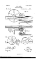
- Figure 1 is a side elevation of the hoistingmachine with the improved overhauling apparatus applied to it.
- Fig. 2 is a plan View of the same.
- the hoisting-machine consists, as now in use,
- the shaft 12 is geared with the driving-engine in any approved way, and the pinions h and t are fitted loosely,to be put in gear by the clutch, according as the fast or slow speed is required for light or heavy loads.
- This reversing-wheel a may be arranged to be thrust between said wheels Z and m, as represented in Figs. 5 and 6; but for the purpose of more rapid action it is preferred to fit said wheel a on acounter-shaft, w, having a wheel, :0, gearing with a larger wheel, 1;, on shaft a, for multiplying the speed, said shaft to being mounted in eccentric bearings q to which a foot'lever or hand-lever, z, is con nected suitably for shifting its wheels a and :0 into and out of gear with the wheels Z and 0, when required.
- Any other approved means of shifting the reversing-wheel may be used, as a lever swinging on a fulcrumpivot and carrying the shaft of said pulley a in one end; and the same lever arrangement or eccentric bearings 1 may be employed with suitable levers or supporting-arms, a, for working them, when it is preferred to dispense with the wheel 2; and arrange the reversing-wheel to work between wheels I and m, in which case said reversing wheel may be arranged under the drivingwheels, to be thrust upward between them as in Fig.
Landscapes
- Engineering & Computer Science (AREA)
- General Engineering & Computer Science (AREA)
- Mechanical Engineering (AREA)
- Jib Cranes (AREA)
Description
(No Model.) 2 Sheets-Sheet 1. 0. G.. ROSS.
HOISTI'NG vMAQHINE.
mvamrom ATTORNEYS l I l b l I l l I I I Patented July 1, 1884 o w J N PETERS. Pholo-Lilllognpller, WaShmglnn. Dv c,
(No Model.) 2 Sheets-Sheet 2.
0. G. ROSS.
HOISTING MAoHiNE. I No. 301,281. Patented July 1, 1884.
WITNESSES: 1 HWENTOR:
BY 1w ATTORNEYS.
35 more clearly.
' llriirnio fs 'r'a'rns Parana? @rrr'cri.
ooRNnLE e. ROSS, on RUTLAND, VERMONT, assrenon TO THE LINCOLN IRON wonKs, or SAME PLAOF.
elm-me- SPECIFICATION forming part of Letters Patent No. 301,281, dated July 1, 1884.
Application filed May 21, 1884. (No model.)
To all whom it 11mg concern.-
Be it known that I, OORNELE G. Ross, of Rutland, in the county of Rutland and State of Vermont, have invented certain new and useful Improvements in Hoisting Machinery,
of which the following is a full, clear, and eX- act description.
This invention relates to hoisting-machines in which a drum with suitable driving; mechm anism and a disconnecting-clutch are employed for winding up the rope of a derrick and unwinding or overhauling the rope, as the quarryanen say, in the handling of heavy stones and other objects in quarries, mines, and the I 5 like'places; and the invention consists of contrivauces for unwinding or overhauling the rope more rapidly than it can be done as these machines are commonly arranged, to economize time when working in deep mines,
quarries, and other places requiring the use hereinafter fully described.
Reference is to be had to the accompanying drawings,for1ning part of this specification, in which similar letters of reference indicate corresponding parts in all the figures.
Figure 1 is a side elevation of the hoistingmachine with the improved overhauling apparatus applied to it. Fig. 2 is a plan View of the same. Fig. 3 is a detail inside elevation on an enlarged scale to show the apparatus Fig. 4 is a plan View of the apparatus of Fig. 3 inverted, and Figs. 5 and 6 represent modifications of the apparatus in side elevation.
The hoisting-machine consists, as now in use,
0 of the rope-winding drum a, mounted on the shaft I), which is geared by the wheel a and pinion cl with the shaft 0, which is geared by differential wheels f g and pinions h t and the clutch j with the shaft 7;, which has a friction .5 wheel, Z, working between the friction-driver m on the driving-shaft n and the friction-post o, the shaft carrying said wheel [having its bearing in the eccentric p, by which the wheel Z is readily shifted from driver m to the middie position or to the :Irictioupost, according as the drum is to be turned by the driver on to raise the load, or be held fast to suspend the load by the friction-post, or to let'the load descend, or to allow the rope to be overhauled, said eccentric having a shifting-lever, q,.with a stop-latch, s, and a holding-rack, t, arranged. for shifting and setting it, as described. The shaft 12 is geared with the driving-engine in any approved way, and the pinions h and t are fitted loosely,to be put in gear by the clutch, according as the fast or slow speed is required for light or heavy loads.
These machines are constructed very heavy and strong for lifting great weights, and work with so much friction that the overhauling or unwinding of the rope for lowering the tackle to take a new loadrequires the gearing to be turned backward by the shaft k when the wheel 1 is set in the middle position, for which said shaft is commonly fitted with arms, like a Windlass, to be worked by hand, which is a very slow process, consuming too much time when working in quarries of much depth, and which construction it is now proposed to improve by the employment of a reversing friction-wheel, a, between the wheel Z and the driver at, or a multiplying-wheel, t, on the shaft a, to utilize the driving-power for overhauling the rope. This reversing-wheel a may be arranged to be thrust between said wheels Z and m, as represented in Figs. 5 and 6; but for the purpose of more rapid action it is preferred to fit said wheel a on acounter-shaft, w, having a wheel, :0, gearing with a larger wheel, 1;, on shaft a, for multiplying the speed, said shaft to being mounted in eccentric bearings q to which a foot'lever or hand-lever, z, is con nected suitably for shifting its wheels a and :0 into and out of gear with the wheels Z and 0, when required.
Any other approved means of shifting the reversing-wheel may be used, as a lever swinging on a fulcrumpivot and carrying the shaft of said pulley a in one end; and the same lever arrangement or eccentric bearings 1 may be employed with suitable levers or supporting-arms, a, for working them, when it is preferred to dispense with the wheel 2; and arrange the reversing-wheel to work between wheels I and m, in which case said reversing wheel may be arranged under the drivingwheels, to be thrust upward between them as in Fig. 5; or it may be arranged above them to produce the requisite friction by its weight and the weight of its arms, the supportingarms a being fitted to pivot-studs b of the eccentric bearings 3 Having thus described my invention, I claim as new and desire to secure by Letters Patent- 1. The combination of the reversing-wheel u and an eccentric shiftingbox, 3 with the driving-wheels Z and m of the hoisting-machine,
substantially as described.
2. The combination of the reversing-wheel a, wheel as, multiplying-wheel v, eccentric shift- I 5 ing-boxes y, and lever z with the drivingwheels 1. and m of the hoisting-machine, substantially as described.
OORNELE G. ROSS. Witnesses:
PATRICK KELLY,
NATHANIEL S. STEARNS.
Publications (1)
| Publication Number | Publication Date |
|---|---|
| US301281A true US301281A (en) | 1884-07-01 |
Family
ID=2370455
Family Applications (1)
| Application Number | Title | Priority Date | Filing Date |
|---|---|---|---|
| US301281D Expired - Lifetime US301281A (en) | Wobks |
Country Status (1)
| Country | Link |
|---|---|
| US (1) | US301281A (en) |
-
0
- US US301281D patent/US301281A/en not_active Expired - Lifetime
Similar Documents
| Publication | Publication Date | Title |
|---|---|---|
| US301281A (en) | Wobks | |
| US1008338A (en) | Tractor-hoist and tractor-excavator. | |
| US402378A (en) | Wrecking-car | |
| US166468A (en) | Improvement in windlasses | |
| US44124A (en) | Improvement in hoisting apparatus | |
| US548725A (en) | Traveling crane | |
| US81289A (en) | Improvement in hoisting-machines | |
| US253714A (en) | Hoisting-machine | |
| US220408A (en) | Improvement in windlass and derrick for boring artesian and other wells | |
| US285010A (en) | Apparatus for drilling wells | |
| US1026508A (en) | Well-drilling machine. | |
| USRE7727E (en) | Improvement in hqisting-machines | |
| US522078A (en) | Pulley-block | |
| US1000537A (en) | Hoisting and conveying apparatus. | |
| US308780A (en) | Revolving steam-derrick | |
| US279305A (en) | Hoisting apparatus | |
| US1281393A (en) | Safety device for forging-manipulators. | |
| US248286A (en) | bruner | |
| US1125838A (en) | Gearing. | |
| US475834A (en) | Elevator | |
| US255844A (en) | dobbie | |
| US210850A (en) | Improvement in hoisting-machines | |
| US5828A (en) | Hachine for hoisting | |
| USRE9153E (en) | alerx | |
| US906951A (en) | Hoist. |