US300809A - Adding-machine - Google Patents
Adding-machine Download PDFInfo
- Publication number
- US300809A US300809A US300809DA US300809A US 300809 A US300809 A US 300809A US 300809D A US300809D A US 300809DA US 300809 A US300809 A US 300809A
- Authority
- US
- United States
- Prior art keywords
- shaft
- cylinder
- machine
- wheel
- operating
- Prior art date
- Legal status (The legal status is an assumption and is not a legal conclusion. Google has not performed a legal analysis and makes no representation as to the accuracy of the status listed.)
- Expired - Lifetime
Links
- 230000000994 depressed Effects 0.000 description 10
- 238000010276 construction Methods 0.000 description 6
- 210000003414 Extremities Anatomy 0.000 description 4
- 239000007787 solid Substances 0.000 description 4
- 210000003746 Feathers Anatomy 0.000 description 2
- 240000001973 Ficus microcarpa Species 0.000 description 2
- RYGMFSIKBFXOCR-UHFFFAOYSA-N copper Chemical compound [Cu] RYGMFSIKBFXOCR-UHFFFAOYSA-N 0.000 description 2
Images

Classifications
-
- G—PHYSICS
- G06—COMPUTING; CALCULATING OR COUNTING
- G06G—ANALOGUE COMPUTERS
- G06G1/00—Hand manipulated computing devices
- G06G1/02—Devices in which computing is effected by adding, subtracting, or comparing lengths of parallel or concentric graduated scales
- G06G1/04—Devices in which computing is effected by adding, subtracting, or comparing lengths of parallel or concentric graduated scales characterised by construction
- G06G1/08—Devices in which computing is effected by adding, subtracting, or comparing lengths of parallel or concentric graduated scales characterised by construction with circular or helical scales
- G06G1/085—Devices in which computing is effected by adding, subtracting, or comparing lengths of parallel or concentric graduated scales characterised by construction with circular or helical scales borne by a cylinder
Definitions
- My invention relates to an improvement in adding-machines; and it consists', rst, in an adding-machine, in the combination of an endwise-moving registering-cylinder having the numbers spirally and consecutively arranged thereon, an endwise-moving shaft, and a suitable mechanism for rotating and moving the shaft endwise, second, in the combination of '2o an endwise-moving registering-cylinder having the numbers spirally and consecutively arranged thereon, an endwise-moving shaft having a spiral groove, and a suitable mechanism for rotating ⁇ and moving the shaft endwise; third, in the combination of the cylinder having the numbers spirally arranged thereon, an endwise-moving shaft to which the cylinder is secured, and which is provided with a thread or groove, and bearings for the 3o shaft, with la spur-wheel which is feathered upon the shaft, a pawl, and a suitable operating mechanism; fourth, in the combination of the cylinder having the numbers arranged spirally thereon, the shaft provided with a groove or thread, a
- the object of my invention is to produce an adding-machine that is simple in construction, is positive and accurate in its operation, and
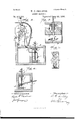
- Figure l is a front elevation of an adding-machine embodyiug my invention, portions of the casing being removed so as to disclose the operating mechanism.
- Fig. 2 is a vertical cross-sec- 'of which project the operating-rods C, which tional View taken on the line X X of Fig. l.
- Fig. 3 is a detailed longitudinal sectional view of the cylinder and the operating-shaft and its bearings on the line Y Y of Fig. l.
- Fig. 4 is a detailed view of one of the operatingkeys.
- Fig. 5 is a detached view of the cylinder alone.
- A represents an inclosing-case, of any suit- 6o able construction, in which the operating mechanism is located. This case is provided with an aperture, A.
- B represents the key-board, from the face have the buttons D on their upper ends, and have their lowerl ends socketed in a bar, E, that extends along the bottom of the case below the key-board, thus holding the rods in an upright position and allowing them a ver- 7o tical movement.
- These operating-rods are preferably nine in number, representing figures from l to 9, figure l being onthe left hand of the key-board, and the others extending therefrom to the right in numerical order.
- Each of these rods has its upper end screwthreaded, as at C', above the key-board, and has the clamping-nuts C2 applied thereon, the function of these nuts being to so adjust the rod in relation to the key-board that the rod will, upon being depressed, cause the addingcylinder to rotate a distance commensurate with the number that the rod may represent.
- the nuts on the said rod 3 should be so adjusted as to cause the cylinder to rotate through three spaces, and thus cause the number 7 to appear through the opening, and so on for each of the other rods.
- F represents an operating-lever, which eX- tends alongthe case beneath the key-board, is pivoted in said case at its right extremity, as at F', and is provided with the spring F at its left extremity, the function of this spring being to keep the lever normally in the hori- IOO Zontal position shown in liilig. l in solid lines. Extending through the rods C are the transverse pins C, which bear upon the upper edge of the lever li, and thereby depress said lever when one of the rods (l is depressed.
- rllhis lever G is l'ulcrumed to the rod at Gf, is eonlined at its inner end by the link Gi, and has its outer i'ree end extending through an opening, G, made :in the outer l'ace ol;n the case. ln the upper portion, lil, of the case is secured the operating-shalt l.
- This shaft l has one el its ends provided with a large open screw-thread, lf, which extends along the shalt a suitable distance.
- the smooth end ol' the shalt is provided with a groove, l?.
- the threaded end of the shalt is screwed through a nut, l, secured in the ease, which nut is provided with an inner extension, lli', long enough to Yl'orm a solid bearing l'or the sha-lt.
- the smooth end ol' lthe shalt passes through bearings L, secured to the opposite side el' the case, and in between these bearings and upon the shalt lf is placed a spur or ratchet wheel, M, provided with a feather, which 'lits into the groove lZ of the shalt, and thus causes the wheel M to rotate with the shalt, and at the same time allow the shalt an independent endwise movement in its bearings.
- r,llo one end of the shalt is attached a crank, J.
- ltigidly secured to the shaft l is a cylinder or drum, N, which may be ol any desired length.
- N a cylinder or drum, N, which may be ol any desired length.
- N a cylinder or drum, N, which may be ol any desired length.
- ⁇ l'ace of this cylinder are inscribed numbers from il. up to as large a number as may be desired. These numbers are arranged spirally upon. the cylinder, number l. being at the right thereoi, and there are as many numbers placed upon one spiral on thel cylinder as there are ratchets or teeth upon the wheel M. ll1us,il' there besevcnty-seven ratchcts upon said wheel, the numbers from il. to 7 7 inclusive, will make one spiral en the iaee of the cylinder. linrthen the spiral. threads l upon the shaft l must have as wide a space between them as there is between the dividing spiral
- O represents a pawl having a rearward ex tension, O.
- This pawl pivotedin a l'rame, Rwhich has its lower bil'ureated ends, l, pivn oted upon the shalt '.l on both sides ot' the bearings L.
- the pawl U engages with the ratchet-wheel M, and is provided wi th a spring, Ot", for making its action positive.
- lt represents a detentspring, which is secured in the rear side of the ease at its lower end, and has its upper l'ree end engaging with the rear side of the ratchet-wheel M.
- This spring is considerablybroader than the wheel. M, and projects a suitable distance to the lel't ci' said wheel.
- S represents a llatrod whiehproiects above the top ofthe case 'through a slit, ll, formed therein, has a button, S', secured to its upper end, and has its lower end passed through.
- .llhis rod is Ai'nrther provided with a stop, ti, for limiting its upward movement, a spring, S, l'or keeping it normally in that position, asv shown at Fig. 2, and incline Si), bearing against the projecting upper side ol" the detent-spring t, and a tap ⁇ pet-pin, S".
- Vhen the rod is depressed, the pin i5 strikes against the upper side of the rearward extension of the pawl. O, throwing said pawl out oi ⁇ connection with the ratchetwheel M,and the incline 55" presses the detentspring lt backward out ol' contact with the wheel M at the same time.
- T represents a connecting-rod, the upper end ol which is pivoted in the pivoted frame l?, while its lower end is secured in the operatinglever F.
- the machine is then ready :l'or use in adding lgures.
- a brake-shoe V, which is made ol.' some soft si'lbstanee, preferablyindia-rubher, and which :is caused to bear upon the cylinder at any suitable point.
- A. set-screw, NV enables the brake-shoe to bear against the cylinder with any requisite l'orec.
Description
(No Model.) K 2 Sheets-Sheet 1.
W. G. SMALSTIG.
ADDING MACHINE. N0. 800,800. Patented June 24, 1884.
N. PEYERS, mulvLimognpmr. wnhinpun. D. C4
. 04636 4 @any ZUM 7//// (No Model.)
/ ///&X\
' UNITED STATES Armar Erich.
VILLIAM C. SMALSTIG, OF SPRINGFIELD, MISSOURI.
ADDING-MACHINE.
SPECIFICATION forming part of Letters Patent No. 300,809, dated June 24, 1884.
Application filed October 6,1883. (No model.)
To all whom it may concern:
Be it known that I, WILLIAM C. SMALsrIG, of Springfield, in the county of Greene and State of Missouri, have invented certain new and useful Improvements in Adding-Machines; and I do hereby declare the following to be a full, clear, and exact description of the invention, such as will enable others skilled in the art to which it pertains to make and use it, 1o reference bein g had to the accompanying draw-- ings, which form part of this specification.
My invention relates to an improvement in adding-machines; and it consists', rst, in an adding-machine, in the combination of an endwise-moving registering-cylinder having the numbers spirally and consecutively arranged thereon, an endwise-moving shaft, and a suitable mechanism for rotating and moving the shaft endwise, second, in the combination of '2o an endwise-moving registering-cylinder having the numbers spirally and consecutively arranged thereon, an endwise-moving shaft having a spiral groove, and a suitable mechanism for rotating` and moving the shaft endwise; third, in the combination of the cylinder having the numbers spirally arranged thereon, an endwise-moving shaft to which the cylinder is secured, and which is provided with a thread or groove, and bearings for the 3o shaft, with la spur-wheel which is feathered upon the shaft, a pawl, and a suitable operating mechanism; fourth, in the combination of the cylinder having the numbers arranged spirally thereon, the shaft provided with a groove or thread, a nut which forms one of the bearings for the shaft, a spur-wheel which is feathered upon the shaft, a frame which is pivotcd on said shaft, a pawl, a detent, and suitable operating mechanism; fth, in the 4o combination and arrangement of parts, which will be more fully described hereinafter.
The object of my invention is to produce an adding-machine that is simple in construction, is positive and accurate in its operation, and
can be manufactured and sold at a much lower cost than any similar machine now upon the market.
In the accompanying drawings, Figure l is a front elevation of an adding-machine embodyiug my invention, portions of the casing being removed so as to disclose the operating mechanism. Fig. 2 is a vertical cross-sec- 'of which project the operating-rods C, which tional View taken on the line X X of Fig. l.
Fig. 3 is a detailed longitudinal sectional view of the cylinder and the operating-shaft and its bearings on the line Y Y of Fig. l. Fig. 4 is a detailed view of one of the operatingkeys. Fig. 5 is a detached view of the cylinder alone.
A represents an inclosing-case, of any suit- 6o able construction, in which the operating mechanism is located. This case is provided with an aperture, A.
B represents the key-board, from the face have the buttons D on their upper ends, and have their lowerl ends socketed in a bar, E, that extends along the bottom of the case below the key-board, thus holding the rods in an upright position and allowing them a ver- 7o tical movement. These operating-rods are preferably nine in number, representing figures from l to 9, figure l being onthe left hand of the key-board, and the others extending therefrom to the right in numerical order. Each of these rods has its upper end screwthreaded, as at C', above the key-board, and has the clamping-nuts C2 applied thereon, the function of these nuts being to so adjust the rod in relation to the key-board that the rod will, upon being depressed, cause the addingcylinder to rotate a distance commensurate with the number that the rod may represent. Thus, should the number 4 on the cylinder appear through the opening in the case and the rod 3 be depressed, the nuts on the said rod 3 should be so adjusted as to cause the cylinder to rotate through three spaces, and thus cause the number 7 to appear through the opening, and so on for each of the other rods. The lower ends of these rods have the coiled extensile springs C around them, which springs bear between the upper side of the bar E and the transverse pin C, with which each of the operating-rods is provided. rIhe function of these springs is to keep the operating-rods normally at the upper limit of their movement.
F represents an operating-lever, which eX- tends alongthe case beneath the key-board, is pivoted in said case at its right extremity, as at F', and is provided with the spring F at its left extremity, the function of this spring being to keep the lever normally in the hori- IOO Zontal position shown in liilig. l in solid lines. Extending through the rods C are the transverse pins C, which bear upon the upper edge of the lever li, and thereby depress said lever when one of the rods (l is depressed.
In Fig. Al l illl'istrate akey-lever, which may be applied to each el' the operating-rods should greater leverage be desirable, in order to lessen the labor of operating the machine. rllhis lever G is l'ulcrumed to the rod at Gf, is eonlined at its inner end by the link Gi, and has its outer i'ree end extending through an opening, G, made :in the outer l'ace ol;n the case. ln the upper portion, lil, of the case is secured the operating-shalt l. This shaft l has one el its ends provided with a large open screw-thread, lf, which extends along the shalt a suitable distance. The smooth end ol' the shalt is provided with a groove, l?. The threaded end of the shalt is screwed through a nut, l, secured in the ease, which nut is provided with an inner extension, lli', long enough to Yl'orm a solid bearing l'or the sha-lt. The smooth end ol' lthe shalt passes through bearings L, secured to the opposite side el' the case, and in between these bearings and upon the shalt lf is placed a spur or ratchet wheel, M, provided with a feather, which 'lits into the groove lZ of the shalt, and thus causes the wheel M to rotate with the shalt, and at the same time allow the shalt an independent endwise movement in its bearings. r,llo one end of the shalt is attached a crank, J.
ltigidly secured to the shaft l is a cylinder or drum, N, which may be ol any desired length. Upon the `l'ace of this cylinder are inscribed numbers from il. up to as large a number as may be desired. These numbers are arranged spirally upon. the cylinder, number l. being at the right thereoi, and there are as many numbers placed upon one spiral on thel cylinder as there are ratchets or teeth upon the wheel M. ll1us,il' there besevcnty-seven ratchcts upon said wheel, the numbers from il. to 7 7 inclusive, will make one spiral en the iaee of the cylinder. linrthen the spiral. threads l upon the shaft l must have as wide a space between them as there is between the dividing spiral lines N on the cylinder.
O represents a pawl having a rearward ex tension, O. This pawl pivotedin a l'rame, Rwhich has its lower bil'ureated ends, l, pivn oted upon the shalt '.l on both sides ot' the bearings L. The pawl U engages with the ratchet-wheel M, and is provided wi th a spring, Ot", for making its action positive.
lt represents a detentspring, which is secured in the rear side of the ease at its lower end, and has its upper l'ree end engaging with the rear side of the ratchet-wheel M. This spring is considerablybroader than the wheel. M, and projects a suitable distance to the lel't ci' said wheel.
S represents a llatrod whiehproiects above the top ofthe case 'through a slit, ll, formed therein, has a button, S', secured to its upper end, and has its lower end passed through. a
slitted bearingplate, Si, screwed to the inner side ot' the case. .llhis rod is Ai'nrther provided with a stop, ti, for limiting its upward movement, a spring, S, l'or keeping it normally in that position, asv shown at Fig. 2, and incline Si), bearing against the projecting upper side ol" the detent-spring t, and a tap` pet-pin, S". Vhen the rod is depressed, the pin i5 strikes against the upper side of the rearward extension of the pawl. O, throwing said pawl out oi` connection with the ratchetwheel M,and the incline 55" presses the detentspring lt backward out ol' contact with the wheel M at the same time.
T represents a connecting-rod, the upper end ol which is pivoted in the pivoted frame l?, while its lower end is secured in the operatinglever F. When the lever l? is depressed by one ol the keys, the movement of the lever l? is conununieated to the cylinderN throi'lgh the rod T, :trame l, pawl O, ratchet* wheel M, and shalt l, and the cylindermovcs through as many spaces as the number that the key represents. When the wheel M is released, as above stated, the crank .l can be turned backward, so as to move the cylinder to the lel't until the cipher thereon is visible through the aperture A. The machine is then ready :l'or use in adding lgures. In order to prevent any possible 'inaccuracy in the operation otl my machine by reason ol` the momentum of the registeringcylinder, ,l provide a brake-shoe, V, which is made ol.' some soft si'lbstanee, preferablyindia-rubher, and which :is caused to bear upon the cylinder at any suitable point. A. set-screw, NV, enables the brake-shoe to bear against the cylinder with any requisite l'orec.
The operation will be very readily understood :l'rom the foregoing deseri `rtion and by reference to the drawings hereto 4ftached.
I do not desire to limit myself to the precise construction and arriinlgement et' parts hereinbei'ore described, as itis obvious that many modilications maybe made therein without departing l'roin the spirit ot' my invention.
llaving thus described my invention, l elai1nl. ln an addiiig-machine, a registering-cylinder mounted on an endwise-moving shalt, and having the numbers spirally and consecutively arranged npon it, in combination with suitable mechanism for rotating and moving the shalt lengthwise, substantially as specilied.
2. ln an adding-machine, 'the combination ol the cylinder N, having the numbers spirally and consecutivelyarranged thereon, the shalt l', having the spiral. 'thread or groove l, and suitableaetnati ng mechanism, si'lbstantiall f as set forth.
3. ln an adding-machine, the combination ol" the cylinder N, having the numbers spirally and consecutively arranged thereon, the shalt l, having the spiral thread or groove l and crank` J', and suitable actuating inechan ism, substantially as described.
In an adding-machuie, 'the combination ICI of the cylinder N, having the numbers spirally and consecutively arranged thereon, shaft I, having thread or groove I', bearings for said shaft, Wheel M, feathered to said shaft, .pawl O, and suitable actuating mechanism; substantially as shown and described.-
5. In an adding-machine, the combination of the cylinder N, having the numbers spirally and consecutively arranged thereon, shaft I, having a thread or groove, I', bearings for said shaft, Wheel M, feathered to said shaft, paWl O, suitable actuating mechanism, and detent R, substantially 4as set forth.
6. In an adding-machine, the combination of the cylinder N, having the numbers spirally and consecutively arranged thereon, shaft I, having a thread or groove, I', nut K, forming a bearing for said shaft, Wheel M, feathered to said shaft, frame l?, pivoted on said shaft, paWl O, pivoted in frame IJ, detent R, and suitable actuating mechanism, substantially as specified.
7. In an adding-machine, the combination of the cylinder N, shaft I, crank J wheel M, frame I?, pawl O, detent R, tripping-rod S, and suitable operating mechanism, substantially as shown and described.
8. In an adding-machine, the combination of the registering-cylinder N, shaft I, crank J Wheel M, frame I), pawl O, detent R, tripping-rod S, connecting-rod T, operating-lever F, spring F2, and operating-keys C, substantially as set forth.
9. In an adding-machine, the combination of the registering-cylinder N, shaft I, crank J, Wh eel M, frame I), paWl O, detent R, trippingrod S, connecting-rod T, operating-lever F,
Spring F2, and operating-keys C, having adj usting devices, substantially as specified.
10. In an adding-machine, the combination of the registering-cylinder N, shaft I, crank J, Wheel M, frame I), paWl O, detent R, trippingrod S, connecting-rod T, operating-lever F, spring F2, and operating-keys C, having adjusting devices C2 and springs C3,substantially as set forth.
`1l. In an adding-machine, the combination of the registering-cylinder N, brake V, shaft I. crank J, Wheel M, frame I?, pawl 0detent R, tripping-rod S, connecting-rod T, operatinglever F, spring F2, and operating-keys C, al1 combined and arranged to operate substantially in the manner described.
In testimony whereof I affix my signature in presence of two witnesses.
p WV. C. SMALSTIG. Witnesses:
J. T. MEANs, WM. MoADAMs.
Publications (1)
| Publication Number | Publication Date |
|---|---|
| US300809A true US300809A (en) | 1884-06-24 |
Family
ID=2369985
Family Applications (1)
| Application Number | Title | Priority Date | Filing Date |
|---|---|---|---|
| US300809D Expired - Lifetime US300809A (en) | Adding-machine |
Country Status (1)
| Country | Link |
|---|---|
| US (1) | US300809A (en) |
Cited By (1)
| Publication number | Priority date | Publication date | Assignee | Title |
|---|---|---|---|---|
| AU661208B2 (en) * | 1992-10-19 | 1995-07-13 | Tapani Tirkkonen | A bag for curing food |
-
0
- US US300809D patent/US300809A/en not_active Expired - Lifetime
Cited By (1)
| Publication number | Priority date | Publication date | Assignee | Title |
|---|---|---|---|---|
| AU661208B2 (en) * | 1992-10-19 | 1995-07-13 | Tapani Tirkkonen | A bag for curing food |
Similar Documents
| Publication | Publication Date | Title |
|---|---|---|
| US300809A (en) | Adding-machine | |
| US415982A (en) | Register | |
| US256591A (en) | Adding-machine | |
| US994081A (en) | Ticket printing and delivering machine. | |
| US1012539A (en) | Set-works for sawmills. | |
| US563435A (en) | Adding-machine | |
| US566430A (en) | Register or counter | |
| US609938A (en) | keyes | |
| US633374A (en) | Adding and subtracting machine. | |
| US309035A (en) | Adding-machine | |
| US562143A (en) | mcg-inty | |
| US873754A (en) | Registering-counter. | |
| US385265A (en) | Cash indicator | |
| US28006A (en) | Machine toe adding- numbers | |
| US292256A (en) | Adding machine | |
| US495259A (en) | James p | |
| US446788A (en) | Grain-register | |
| US555038A (en) | dudley | |
| US277627A (en) | btettheb | |
| US515888A (en) | Fare-register | |
| US321062A (en) | Mechanical movement | |
| US537902A (en) | Automatic receding sawmill set-works | |
| US1011426A (en) | Clutch mechanism. | |
| US198761A (en) | Improvement in turnstile-registers | |
| US217220A (en) | Improvement in grain-tallies |