US3003233A - Electric shaver shearing head assembly - Google Patents
Electric shaver shearing head assembly Download PDFInfo
- Publication number
- US3003233A US3003233A US812702A US81270259A US3003233A US 3003233 A US3003233 A US 3003233A US 812702 A US812702 A US 812702A US 81270259 A US81270259 A US 81270259A US 3003233 A US3003233 A US 3003233A
- Authority
- US
- United States
- Prior art keywords
- spacer bar
- heads
- bar
- shearing
- electric shaver
- Prior art date
- Legal status (The legal status is an assumption and is not a legal conclusion. Google has not performed a legal analysis and makes no representation as to the accuracy of the status listed.)
- Expired - Lifetime
Links
Images
Classifications
-
- B—PERFORMING OPERATIONS; TRANSPORTING
- B26—HAND CUTTING TOOLS; CUTTING; SEVERING
- B26B—HAND-HELD CUTTING TOOLS NOT OTHERWISE PROVIDED FOR
- B26B19/00—Clippers or shavers operating with a plurality of cutting edges, e.g. hair clippers, dry shavers
- B26B19/02—Clippers or shavers operating with a plurality of cutting edges, e.g. hair clippers, dry shavers of the reciprocating-cutter type
- B26B19/04—Cutting heads therefor; Cutters therefor; Securing equipment thereof
Description
Oct. 10, 1961 A. R. VAN BAELEN ELECTRIC SHAVER SHEARING HEAD ASSEMBLY Filed May 12, 1959 United States Patent Delaware Filed May 12, 1959, Ser. No. 812,702 6 Claims. (CI. 30-43) This invention relates to electric shaver constructions in which shearing heads are to be assembled, as a unit, with a spacer bar between pairs of heads, the major object being to provide for the ready assembling and secure holding of the components but without the usually employed screws.
In the preferred form of the invention to be described, separate means are providedone for restraining the heads against sliding movement with respect to the spacer bar and the other for clamping the heads against lateral separation from the bar.
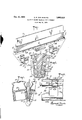
Other objects and advantages will be readily apparent from the following description of the accompanying drawings which illustrate the invention as applied to the clamping together of a single pair of shearing heads, FIG. 1 being an exploded perspective view of the spacer bar and clamping means, FIG. 2 a fragmentary bottom plan View of the assembled unit, FIG. 3 a vertical section on the line 33 of FIG. 2 and FIG. 4 a fragmentary, vertical section on the line 44 of FIG. 2, on an enlarged scale.
The spacer bar, generally designated 1, incorporates locating means for the shearing heads, such means herein comprising a recess in each side of the bar, formed by making a portion of the bar of downwardly tapering cross section. The recessed portion is of less length than that of the bar so that it is constituted by the sloped, side faces 2, the end faces 3 and the bottom faces or seats 4. When located in these recessed portions of the bar, the shearing heads, generally designated 10, are restrained against sliding movement, both endwise and downwardly, with respect to the spacer bar.
The heads are secured against lateral separation from the bar by spring clamping means, shown as comprising two U-shaped clips, 11 and 12, having what will be referred to as center portions 13, '14 and legs 15, 17 and 16, 18. To permit the upward insertion of the clips, as is preferred, the heads are provided with bottom openings. In the illustrated form, these bottom openings comprise the open bottoms 19 of the inverted channel members 20 which constitute the base portions of the heads, the walls of the channel members which are adjacent the spacer bar having openings 21, 22 (FIG. 4) to receive appropriate detent formations in the spring clips.
At least one leg of each clip is formed with an angularly disposed detent portion which, by the bias of the spring, is designed to hold one of the heads against upward separation from its bottom seat. Thus, as shown in FIG. 4, the leg 17 of clip 11 is formed with a detent portion 25 which, when the clip is inserted to the point of engaging its center portion with the bottom of the spacer bar, bears against and exerts a downwardly pull upon the edge 27 of opening 22, thereby holding that shearing head down against its seat 4. The leg 18 of clip 12 is similarly formed and, as shown in FIG. 1, this clip is inserted in a reverse position to that of clip 15, so that its detent portion 26 serves the same hold down function for the other shearing head. The other legs of the clips need not be so formed but, instead, may be provided with deformations 29, 30 which, approximately centered in the opposite channel openings, serve a safety or minor cating function.
Lastly, in order to locate the spring clips further and 3,003,233 Ce Patented Oct. 10, 1961 to restrain them against endwise movement with respect to the spacer bar, the bottom of the bar is provided with recesses 35, 36 (FIG. I) which receive the center portions of the clips, as indicated with respect to clip 13 in FIG. 2.
While the construction illustrated and described represents the preferred form of the invention, it will be recognized that the principles exemplified in it may be embodied in various forms and the details varied to meet the needs of particular cases. In the light of the foregoing, the following is claimed:
1. An electric shaver head unit of the kind including a pair of shearing heads having channel shaped base portions separated by and abutting the opposite side faces of a spacer bar, in which: walls of the said base portions which are adjacent the spacer bar are provided with openings, U-shaped spring clip means having the center part of the U engaged with the bottom of the spacer bar, the legs of the U embracing the said Walls and intervening spacer bar and having angularly disposed detent portions adapted to enter said openings in engagement with the lower edges thereof, the bottom of the spacer bar being provided with recesses to receive and locate the center part of the U of the spring clip means.
2. An electric shaver head unit of the kind including a pair of shearing heads having channel shaped base portions separated by and abutting the opposite side faces of a spacer bar, in which: Walls of the said base portions which are adjacent the spacer bar are provided with openings, -U-shaped spring clip means having the center part of the U engaged with the bottom of the spacer bar, the legs of the U embracing the said walls and intervening spacer bar and having angularly disposed detent portions adapted to enter said openings in engagement with the lower edges thereof.
3. In an electric shaver, the combination of a shearing head spacer bar having a portion of downwardly tapered cross section, providing sloped side faces, and also in corporating an integral shearing head seat at the lower edge of each side face, shearing heads disposed one on each side of the spacer bar in engagement with said faces and seats of the spacer bar, each shearing head having a bottom opening, and U-shaped spring clamp means with its legs entered in said openings, said clamp means being biased to hold the shearing heads in engagement with the said spacer bar faces and seats.
4. An electric shaver head unit of the kind including a pair of shearing heads having channel-shaped base portions separated by and abutting the opposite side faces of a spacer bar, in which: walls of the said base portions which are adjacent the spacer bar are provided with openings, U-shaped spring clip means having a detent portion adapted to enter one of said openings, the clip means embracing the said walls and the intervening spacer bar, thereby clamping the same against separation, and in which the spacer bar is provided with locating means engaged by the heads for restraining the same against sliding movement with respect to the bar independently of the spring clip means.
5. In an electric shaver of the kind including a pair of shearing heads separated by and abutting the opposite side faces of an intervening spacer bar, the improvement which comprises the combination of locating means carried by the bar and engaged by the heads to restrain them against longitudinal sliding movement with respect to the bar and spring clip means embracing portions of the shearing heads and the intervening spacer bar, said spring clip means being biased to clamp the heads and bar together and thereby hold them against lateral separation.
6. In an electric shaver, the combination of a shearing head spacer bar having on each side thereof a recess incorporating downwardly and inwardly sloped side faces and, bordering the latter faces, opposed end faces and upwardly directed bottom faces, shearing heads disposed one on each side of the spacer bar with portions located in said recesses and located by all said faces, and means clamping the heads against lateral movement out of the spacer bar recesses.
References Cited in the file of this patent UNITED STATES PATENTS 2,331,453 Carissimi Oct. 12, 1943 5 2,718,694 Scully Sept. 27, 1955 FOREIGN PATENTS 1,110,445 France Oct. 12 1955
Priority Applications (1)
| Application Number | Priority Date | Filing Date | Title |
|---|---|---|---|
| US812702A US3003233A (en) | 1959-05-12 | 1959-05-12 | Electric shaver shearing head assembly |
Applications Claiming Priority (1)
| Application Number | Priority Date | Filing Date | Title |
|---|---|---|---|
| US812702A US3003233A (en) | 1959-05-12 | 1959-05-12 | Electric shaver shearing head assembly |
Publications (1)
| Publication Number | Publication Date |
|---|---|
| US3003233A true US3003233A (en) | 1961-10-10 |
Family
ID=25210379
Family Applications (1)
| Application Number | Title | Priority Date | Filing Date |
|---|---|---|---|
| US812702A Expired - Lifetime US3003233A (en) | 1959-05-12 | 1959-05-12 | Electric shaver shearing head assembly |
Country Status (1)
| Country | Link |
|---|---|
| US (1) | US3003233A (en) |
Cited By (3)
| Publication number | Priority date | Publication date | Assignee | Title |
|---|---|---|---|---|
| US3044168A (en) * | 1960-01-05 | 1962-07-17 | Schick Inc | Spring holding means for electric shaver shearing head |
| US3111754A (en) * | 1961-01-09 | 1963-11-26 | Sperry Rand Corp | Cutter unit attachment and ejectment means for electric dry shaver |
| US3364569A (en) * | 1965-05-28 | 1968-01-23 | Sunbeam Corp | Electric shaver with magnetic latch and clutch actuated clipper |
Citations (3)
| Publication number | Priority date | Publication date | Assignee | Title |
|---|---|---|---|---|
| US2331453A (en) * | 1942-06-27 | 1943-10-12 | Remington Rand Inc | Shaver head mounting |
| US2718694A (en) * | 1950-05-26 | 1955-09-27 | John T Scully | Shaver with hair raising brush |
| FR1110445A (en) * | 1954-09-01 | 1956-02-13 | Adjustable cutting height shaving head |
-
1959
- 1959-05-12 US US812702A patent/US3003233A/en not_active Expired - Lifetime
Patent Citations (3)
| Publication number | Priority date | Publication date | Assignee | Title |
|---|---|---|---|---|
| US2331453A (en) * | 1942-06-27 | 1943-10-12 | Remington Rand Inc | Shaver head mounting |
| US2718694A (en) * | 1950-05-26 | 1955-09-27 | John T Scully | Shaver with hair raising brush |
| FR1110445A (en) * | 1954-09-01 | 1956-02-13 | Adjustable cutting height shaving head |
Cited By (3)
| Publication number | Priority date | Publication date | Assignee | Title |
|---|---|---|---|---|
| US3044168A (en) * | 1960-01-05 | 1962-07-17 | Schick Inc | Spring holding means for electric shaver shearing head |
| US3111754A (en) * | 1961-01-09 | 1963-11-26 | Sperry Rand Corp | Cutter unit attachment and ejectment means for electric dry shaver |
| US3364569A (en) * | 1965-05-28 | 1968-01-23 | Sunbeam Corp | Electric shaver with magnetic latch and clutch actuated clipper |
Similar Documents
| Publication | Publication Date | Title |
|---|---|---|
| US3242570A (en) | Blade tension means for hair clipper blades | |
| US3372522A (en) | Detachable grill assembly for window sash | |
| US2329688A (en) | Snap fastener and trim strip and the like | |
| US4459744A (en) | Razor blade apparatus and method | |
| US2794246A (en) | Disposable razor | |
| KR900017521A (en) | Adjustable fastener | |
| US3400435A (en) | Fastening device | |
| US3003233A (en) | Electric shaver shearing head assembly | |
| US3958691A (en) | Hanger cartridge for facilitating assembly of traverse rods | |
| KR940011372B1 (en) | Energy conductor supporting chain | |
| US3112960A (en) | Universal sliding drawer roller | |
| US2894302A (en) | Spring clip | |
| US3056198A (en) | Adjustable multiple shaving head assembly for electric shavers | |
| US3044168A (en) | Spring holding means for electric shaver shearing head | |
| GB1032858A (en) | Springy support for upholstery | |
| US3039188A (en) | Electric dry shaver | |
| US2323655A (en) | Mount for shearing heads | |
| US2998109A (en) | Mounting clips | |
| US4778096A (en) | Anvil for a disposable stapler | |
| US4701067A (en) | Device for snap fitting an electric apparatus onto a support bar | |
| US3106271A (en) | Grating clamp | |
| US2214519A (en) | Mop head | |
| US3191300A (en) | Guide means for inner cutter of a dry shaver | |
| US2914288A (en) | Spring clip means | |
| US3293686A (en) | Hanger for window sash balance |