US3003196A - Top roll assembly - Google Patents
Top roll assembly Download PDFInfo
- Publication number
- US3003196A US3003196A US831840A US83184059A US3003196A US 3003196 A US3003196 A US 3003196A US 831840 A US831840 A US 831840A US 83184059 A US83184059 A US 83184059A US 3003196 A US3003196 A US 3003196A
- Authority
- US
- United States
- Prior art keywords
- roll
- rolls
- cradle
- top roll
- saddle
- Prior art date
- Legal status (The legal status is an assumption and is not a legal conclusion. Google has not performed a legal analysis and makes no representation as to the accuracy of the status listed.)
- Expired - Lifetime
Links
- 238000009987 spinning Methods 0.000 description 18
- 125000006850 spacer group Chemical group 0.000 description 6
- 238000004519 manufacturing process Methods 0.000 description 4
- 238000009434 installation Methods 0.000 description 3
- 239000002184 metal Substances 0.000 description 3
- 238000003825 pressing Methods 0.000 description 3
- 230000008901 benefit Effects 0.000 description 2
- 238000004140 cleaning Methods 0.000 description 2
- 238000012423 maintenance Methods 0.000 description 2
- 239000000463 material Substances 0.000 description 2
- 239000002991 molded plastic Substances 0.000 description 2
- 229910000831 Steel Inorganic materials 0.000 description 1
- 238000009825 accumulation Methods 0.000 description 1
- 230000009471 action Effects 0.000 description 1
- 230000003749 cleanliness Effects 0.000 description 1
- 239000011248 coating agent Substances 0.000 description 1
- 238000000576 coating method Methods 0.000 description 1
- 238000010276 construction Methods 0.000 description 1
- 230000000994 depressogenic effect Effects 0.000 description 1
- 238000009826 distribution Methods 0.000 description 1
- 230000006872 improvement Effects 0.000 description 1
- 239000004033 plastic Substances 0.000 description 1
- 230000000750 progressive effect Effects 0.000 description 1
- 230000009467 reduction Effects 0.000 description 1
- 230000008439 repair process Effects 0.000 description 1
- 239000012858 resilient material Substances 0.000 description 1
- 239000011435 rock Substances 0.000 description 1
- 238000007789 sealing Methods 0.000 description 1
- 239000010959 steel Substances 0.000 description 1
Images


Classifications
-
- D—TEXTILES; PAPER
- D01—NATURAL OR MAN-MADE THREADS OR FIBRES; SPINNING
- D01H—SPINNING OR TWISTING
- D01H5/00—Drafting machines or arrangements ; Threading of roving into drafting machine
- D01H5/18—Drafting machines or arrangements without fallers or like pinned bars
- D01H5/56—Supports for drafting elements
Definitions
- My invention relates to spinning and roving frames and comprises in particular an improved assembly of top rolls and supporting structure.
- spinning and roving frames include a back bar whichruns the length of the frame and a number of top support arms which are supported from the back bar. These top support arms are arranged to pivot about the back bar and in their operating position they are brought down over the top back, middle and front rolls to support those rolis for rotation with corresponding bottom rolls.
- top support arms and back bars constitute a rather complex structure with a considerable number of parts. In addition totheir complexity, they account also for Significant equipment expense. Most important, though, by. their presence, they hamper the very necessary cleaning operations which are done to' remove lint and fly from the frames and they themselves provide. additional areas for the accumulation of lint. It is customary to provide an air blast to maintain cleanliness about the roving and spinning frames, and the back bars and top support arms bf present frames prevent free circulation andetlicient removal of lint by the air stream. x
- the primary object of my invention is to improve the fquality and efficiency of spinning and roving.
- Another object of my invention is to eliminate the intricate and delicate adjustments customarily required at frequent intervals in the course of operating a spinning or roving frame.
- Still another object of my invention is to improve the strength and consistency of yarn.
- a cradle supporting the middle top roll and rotatably mounted on the middle bottom roll shaft, the cradle having a rearwardly extending finger engaging the bottom of the back bottom roll and including a single adjustment for varying the fixed angular position of the ⁇ cradle
- the finger of the cradle may be designed to contact a fixed element of the frame such as the back bar where circumstances warrant this alternative.
- the back .top roll is supported by a saddle anchored to the middle top roll, and the front top roll is mounted on an arm pivotally :engaged with the saddle; consequently the adjustment of the finger simultaneously and permanently fixes the relationship of all three top rolls to the bottom rolls.
- Another feature of my invention lies in locating the pivot point between the saddle and the top roll supporting arm beneath the axes of the middle and back top rolls, .andso dimensioning the arm that the arc of movement got-the axis of the front top roll intersects the axis of the front bottom roll.
- the result is that no reduction in diameter of the front top roll cots (e.g. following bufling) will alter the location of the bite of the front top and bottom rolls.
- the position of each front top "roll in a spinning or roving frame must be adjusted after bufiing; otherwise yarn quality suffers.
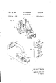
- FIG. 1 is a plan view of an assembly of top and bottom rolls, constructed in accordance with the invention
- PEG. 2 is a view in cross-section along the line 2-2 of FIG. 1,
- FIG. 3 is a View in perspective of the cradle
- 1 16.4 is an exploded view in perspective showing the adjusting elements for the cradle finger
- FIG. 5 is an exploded view in perspective showing the saddle and cooperating front top roll arm
- FIG. 6' is a view in side elevation, partly in cross-section showing a typical top roll
- FIG. 7 is a view in front elevation of the cradle and U-pin
- FIG. 8 is a view in perspective of the U-pin.
- the top rollassembly of my invention is applied to a conventional spinning or roving frame including the'customary base 10 and up standing frame members 12;.
- Each'of the latter has an integral inclined bracket 14 at its upper end, provided with journals supporting three bottom roll shafts; a front bottom roll shaft 16 having at spaced intervals integral enlarged roll portions 22 with knurled or fluted surfaces; a middle bottom roll shaft 13 with knurled or fluted roll portions 24; and a ack bottom roll shaft 20 with knurled or fluted roll portions 26.
- each top roll includes an arbor or shaft 159 on which i disposed a tubular central spacer 18.51 molded upon a knurled surface hand on the shaft 150.
- the spacer 153i is flanked by a pair of tubular sleeves 152 each having an integral shoulder 154; At each end of the arbor 15% is a cot res comprising a ho].
- each cot 156 Pressed into each end of each cot 156 is a cup-shaped member 153. Within each of the cups 158 is a lint sealing assembly of washers lot and a bearing cone 162 on which a race of bearing balls 164 is mounted. The cups and cots turn The middle top roll differs only in employing cots of less diameter, while in the front top roll the spacer 152 is replaced by an integral arm and spacer 114, 118.
- annular V-sh'aped space 159 Between the cups 158 is an annular V-sh'aped space 159. If the strand 30 is directed upon the center of the cot, the space 15? permits the resilient cot to flex, a result which allows operation of the frame without traverse for satisfactorily long periods of cot life.
- top rolls are shown slightly separated from the bottom rolls, in the interest of clarity. In actuality the top rolls are pressed into firm engagement with the bottom rolls.
- the cradle is organized about a pair of flat side members 34 of identical configuration and conveniently made of molded plastic material.
- the side members 34 are maintained in rigid spaced parallel relation by means of a pair of flat stiff metal bars 36 and 38 the ends of which are anchored in sockets formed in the side members.
- Each side member includes a downwardly extending peninsular 40 shaped to form one leg of an arcuate recess 42 open at the bottom of the cradle and including an are slightly in excess of 180.
- the side members 34 are also shaped to form sub stantially U-shapcd recesses 41 opening upwardly and separated from the recesses 42 by thin, flexible webs 46.
- the front edge of each member 34 is provided with an integral lug 48 providing supports for the. mounting of a stiff metal U-pin 130 (of. FIGS. 7 and 8), whose function will later be described.
- U-shaped bracket 5% having aligned recessee 52 of roughly hourglass configuration cut in the rearwardly extending bracket legs.
- a short flat metal bar 54 is held at each end in the recesses 52, and it is important to, note that the hourglass shape of the recesses 52 permit the bar 54 to rock on a horizontal axis through a limited are. (See FIG. 3.)
- a plastic finger tip 58 has a downwardly extending channel portion 60 including a circular recess 61 accommodating a desired number of washers 56 by means of which the bar 54 may be adjustably spaced from the bottom of the inverted channel 60.
- the upper portion of the finger tip 58 is curved as shown at 64 to provide an arcuate seat having a radius approximately equal to that of the back bottom roll 26.
- a machine screw 66 passes through the bottom of the arcuate seat 64 into a hole tapped into the flat bar 54, thus holding the finger tip assembly in place on the bracket 50.
- the assembly includes a pair of the cradles 32, each of which is snapped over the middle bottom roll shaft 18, the side members of each cradle embracing the middle 'bottorn rolls 24.
- the cradles When the cradles are installed, they .flex at the web portions 46 so that the arcuate recesses 42 are temporarily enlarged as they slip over the roll shaft 18. Because these recesses exceed 180, it will be evident that the cradles are removably but firmly locked in place upon the middle bottom roll shaft 15.
- the engagement of the finger tip 58 with the back bottom roll 26 limits the rotation of the cradle 32 about the middle bottom roll shaft in the counter-clockwise direction.
- a middle top roll 124 is mounted on the cradles 32.
- the end caps 170 and spacer sleeves 152 engage the edges of the U-shaped recesses 41.
- a rubber belt or apron 132 passes around the circumference of each of the pair of knurled middle bottom rolls 24 and about the lower leg of the U-pins 130 held in the cradles 32. Similar aprons 134 pass around the circumference of the middle upper top roll 124 and about the upper leg of the U-pins 130. Thus the two aprons cooperate on the strand passing between them.
- the action of the aprons is conventional and requires no further description. However, it is important to note that the U-pin 130 is not of conventional form. It ispro- ,4 vided with a U-shaped clip 132 on the upper surface of the upper leg, the sides of the clip serving as guides maintaining the alignment of the upper aprons 134.
- the vertical position of the discharge end of the nip of the aprons 1.32 and 134 is fixed by the engagement of the finger tip SE5 with the bottom of the back bottom roll 26.
- the distance between the discharge end of the nip of the aprons and the bite of the front rolls 22 and 129 is also critical, and I provide another form of permanent adjustment to take care of it. That dimension may be determined by the breadth of the U-pin 130. If it is found that the distance is too short, for example, I may use a broader U-pin in cooperation with slightly longer aprons. Conversely, a thinner U-pin 130 and shorter aprons are employed if it is found desirable to decrease the distance.
- the integral center sleeve of the middle upper top roll provides a seat for one end of a saddle member 102, best shown inFIG. 5.
- the saddle 102 includes a pair of arcuate fingers 1M and 106 and a depressed center portion 1% including a hemispherical recess 110.
- the finger 14M rests on the center of the middle upwr top roll, and the finger 104 rests on the center portion of the back top roll 70.
- the breadth of the fingers 104 and 166 is sutficient to span enough of the associated top rolls to ensure that the back top roll is firmly gripped and maintained in parallel relation to the middle top roll as well as to the bottom rolls. It is important to observe that the distance between the middle and back top rolls is fixed and that there is no adjustment, contrary to customary practice. Because the top roll assembly of my invention may be installed on spinning and roving frames of various models and manufacture, the required distance between the middle and back top rolls will vary. That is why it is customary to provide some means of adjusting that distance. I have found, however, that, because the distance is critical, it is preferable to use a saddle 102 properly and permanently dimensioned for the particular frame on which the assembly will be used.
- Seated in the socket 110 is the rounded end 112 of a curved arm 114 which terminates at its forward end in a sleeve 118 which forms the center spacer sleeve of the front top roll 119 provided with the customary cots 120.
- the ball and socket engagement of the arm 114 and saddle 102 permits the front top roll 119 to pivot laterally, while vertical movement is restrained by a stirrup 200 as will later be described. Since the, cots 120 of thefront top roll 119 are rotated by their engagement with the driven front bottom rolls, the front top roll 119 is self-aligning. Consequently the front top roll .is automatically maintained in proper parallel relation to the front bottom roll, and, again, no adjustment is necessary.
- the arm 114 may conveniently comprise a steel member having a molded plastic coating and is provided with a plurality of serrations 116 along its upper edge near the forward end.
- the serrations provide adjustable positioning means for a stirrup 200 which projects downwardly between the cradles 32 and between the front and middle bottom roll shafts.
- the upper end of the stirrup is formed with a circular recess by means of which the stirrup may he slipped over the arm 114 and moved to desired position in engagement with one of the serrations 116.
- the lower end of the stirrup 200 is slotted to receive a lever 202 having a hook 204 at its forward end engaging an eye-bolt 206 secured to the frame base 10.
- the rear end of the lever 202 has a slight hook 208 which engages a vertical rod 210 at the lower end of which is a weight (not shown).
- the weight on the end of the rod 210 works through the lever 202, the stirrup 200 and the arm 114 to apply pressure upon all three top rolls.
- the pressure on the front top roll is direct through the arm 114, while the rear end of the arm 114 bears on the saddle member 102 and thereby exerts downward pressure on the middle and back top rolls.
- the stirrup 200 is disposed forwardly of the cradles 32, there is also a force tending to rotate both cradles incounter-clockwise direction, and that force is resisted by the engagement of the finger tip 58 with the bottom of the back bottom rolls 26.
- the necessary adjustment can very simply be accomplished by slipping the upper end of the stirrup 200 into the proper serration 116.
- any reasonable number may be utilized and each given a fixed positionrequiring. no adjustment once set.
- screw adjustments or the like are provided. Variable adjustments such as the screw are either neglectedby unskilled help or require too frequent attention by skilled help. In either case the result is undesirable; pooryarn or undue expense is encountered and these difiiculties are eliminated by the fixed adjustments provided by the serrations and their associated stirrup.
- the setting once established also promotes consistency of output because the system may be taken apart if necessary and reassembled with the identical adjustment existing before disassembly.
- the relative positions of the front top and bottom rolls and their position relative to the discharge end of the bite of the aprons 132 and 134 are of critical importance in the production of quality yarns.
- the arm 114 pivots by reason of the engagement of its rounded end 112 in the hemispherical recess 110 of the saddle 102. It should be noted that the pivot point is below the centers of the middle and back top rolls and that it is so located that, the axis of the front top roll moves through an are which intercepts the axis of the front bottom roll 22. If the diameter of the cots 120 of the front top roll is reduced, as happens when the cots are buffed, the location of the bite of the front top and bottom rolls remains in prccisley the same location.
- the relative positions of the bite of the front top and bottom rolls and the discharge end of the bite of the aprons 132 and 134 are permanently fixed after the finger tip 58 has been adjusted by means of the washers 56.
- the rolls may be disassembled and re-assembled without in any way altering the critical relationships. Consequently a properly installedassembly can never get out of adjustment, and the usual requirement that exceptionally skilled workers dismount and clean top rolls is completely eliminated. The ultimate result is a striking improvement in the quality and consistency of the yarn.
- a roll assembly for spinning and roving frames which include a frame, three spaced parallel bottom rolls and three spaced parallel top rolls
- apparatus for supporting said top rolls in juxtaposition to said bottom rolls comprising a cradle having a first surface for engaging the upper portion of the middle one of said bottom rolls, a second surface for engaging the lower portion of another of said bottom rolls, and means for adjusting th engagement of one of the surfaces with one of said bottom rolls to vary the rotational position of said cradle about the other of said bottom rolls and the position of said top rolls relative to said bottom rolls.
- a roll assembly for spinning and roving frames which includes a frame, spaced parallel back, middle, and front bottom rolls, and spaced parallel back, middle, and front top rolls
- apparatus for supporting said top rolls in juxtaposition to corresponding ones of said bottom rolls comprising a cradle having a first surface rotatable about and engaged by the upper portion of said middle bottom roll and a second surface engaged by the lower portion of said back bottom roll, said middle top roll being mounted for rotation in said cradle, means supported from said cradle for retaining said front and back top rolls in juxtaposition with said front and back bottom rolls, and means for adjusting the distance of said sec; ond surface from the body of said cradle to rotate said cradle about said middle bottom roll and to vary the positions of all of said top rolls relative to corresponding bottom rolls.
- Roll assembly for spinning and roving frames comprising a frame, three spaced parallel bottom rolls mounted in said frame, a cradle engaging the upper portion of the middle bottom roll, a finger secured to said cradle and engaging the bottom of the back bottom roll, a middle top roll mounted in said cradle above the middle bottom roll, a back top roll, a saddle having fingers engaging the tops of the middle and back top rolls, a front top roll, an arm engaging the saddle between said fingers thereof, said arm also engaging said front top roll, and means for applying pressure on said arm to urge the arm, saddle and all .top rolls against the bottom rolls.
- Roll assembly for spinning and roving frames comprising a frame, three spaced parallel bottom rolls mounted in said frame, a cradle engaging the upper portion of the middle bottom roll, a finger secured to said cradle and engaging the bottom of the back bottom roll, a mid dle top roll mounted in said cradle above the middle bottom roll, a back top roll, a saddle having curved fingers engaging the tops of the middle and back top rolls, an arm pivotally engaging the saddle between said fingers, a front top roll secured to said arm, and means for applying pressure on said arm to urge the arm, saddle and all top rolls against the bottom rolls.
- Roll assembly for spinning and roving frames comprising a frame, three spaced parallel bottom rolls mounted in said frame, a cradle engaging the upper portion of the middle bottom roll, a finger secured to said cradle and engaging the bottom of the back bottom roll, a middle top roll mounted in said cradle above the middle bottom roll, a back top roll, a saddle having fingers engaging the tops of the middle and back top rolls, an arm pivotally engaging the saddle between said fingers thereof, a front top roll secured to said arm, the axes of the front top and bottom rolls both lying on an are having as its center the pivot point between said arm and saddle, and means for applying pressure on said arm to urge the arm, saddle and all top rolls against the bottom rolls.
- a cradle rotatably mounted on the middle bottom roll and having an adjustable finger engaging the bottom of another bottom roll, means on the cradle for mounting the middle top roll, a saddle connected to the middle top roll and having means for holding another top roll, a third top roll supporting means pivotally connected to the saddle, and means for applying downward pressure upon said third top roll supporting means at a point between said other and middle top rolls, whereby said cradle is rotated until said finger bears against the bot tom of said other bottom roll, adjustment of said finger serving simultaneously to vary the positions :of all three top rolls with respect to the bottom rolls.
- a spinning or roving frame having front, middle and back bottom rolls and roll shafts, the combination of a cradle mounted on the middle bottom roll shaft, a finger secured to said cradle and bearing upon one of the other bottom roll shafts to limit rotation of the cradle, a middle top roll carried in said cradle, a back top roll, a saddle connected to the middle top roll for mounting the back top roll over the back bottom roll, a front top roll, means secured to said saddle for, mounting said front top roll over the front bottom roll, means for weighting said means, and means for varying the length of said finger in order simultaneously to adjust the positions of all three top rolls with respect to the bottom rolls.
- a cradle mounted on the middle bottom roll shaft, means fixed to said cradle to limitrotation of said cradle, a middle top roll carried in said cradle, a back top roll, a saddle connected to the middle top, roll for mounting the back top roll over the back bottom roll, a front top roll, means secured to said saddle for mounting said front top roll over the front bottom roll, means for weighting said means, and means for varying the length of said means fixed to said cradle in order simultaneously to adjust the positions of all three top rolls with respect to the bottom rolls.
- a cradle rotatably mounted on the, middle bottom roll and having a finger engaging the bottom .of another bottom roll
- the middle top roll rotatably mounted on said cradle
- a saddle engaging the tops of the middle'and another top roll
- an arm pivotally engaging the saddle between said middle top roll and said. other top roll
- said arm secured to the third top roll, and means for applying downward pressure upon said arm, whereby said cradle is rotated until said finger bears against the bottom of said other bottom roll, and said top rolls are urged into engagement with said bottom rolls.
Landscapes
- Engineering & Computer Science (AREA)
- Mechanical Engineering (AREA)
- Textile Engineering (AREA)
- Spinning Or Twisting Of Yarns (AREA)
Description
1961 K. P. SWANSON 3,003,196
TOP ROLL ASSEMBLY 7 Filed Aug- 5. 1959 4 Sheets-Sheet 1 FIG. I INVENTOR.
KENNETH P. SWANSON mm, mm, mm a. mum
ATTORNEYS Oct. 10, 1961 K. P. SWANSON 3,003,196
TOP ROLL ASSEMBLY Filed Aug. 5, 1959 4 Sheets-Sheet 2 I 202 FIG. 2 I T lllllll zzvmvron. KENNETH P. SWANSON {\EMWAY, JENNEY, WiTTER & WLWT ATTORNEYS V Oct. 10, 1961 K. P. SWANSON TOP ROLL ASSEMBLY 4 Sheets-Sheet 3 Filed Aug. 5, 1959 INVENTOR. KEN NETH P. SWANSON KENWAY, JENNEY, WITTER & HILDREU'I ATTORNEYS 4 Sheets-Sheet 4 INVENTOR. KENNETH Ff SWANSON KiHWAY, JENNEY, WITTER & HILDRETH,
ATTORNEYS K. P. SWANSON TOP ROLL ASSEMBLY Oct. 10, 1961 Filed Aug. 5. 1959 Un e S at s Patent 3,093,196 TOP R'SLL ASSEMBLY Kenneth P. Swanson, Abington, Mass, assignor to Progressive Engineering, Inc., Rockland, Mass, :1 corporation of Massachusetts Filed Aug. 5, 1959, Ser. No. 831,840
11 Claims. (Cl. 19-131) My invention relates to spinning and roving frames and comprises in particular an improved assembly of top rolls and supporting structure.
Currently available spinning and roving frames include a back bar whichruns the length of the frame and a number of top support arms which are supported from the back bar. These top support arms are arranged to pivot about the back bar and in their operating position they are brought down over the top back, middle and front rolls to support those rolis for rotation with corresponding bottom rolls.
The top support arms and back bars constitute a rather complex structure with a considerable number of parts. In addition totheir complexity, they account also for Significant equipment expense. Most important, though, by. their presence, they hamper the very necessary cleaning operations which are done to' remove lint and fly from the frames and they themselves provide. additional areas for the accumulation of lint. It is customary to provide an air blast to maintain cleanliness about the roving and spinning frames, and the back bars and top support arms bf present frames prevent free circulation andetlicient removal of lint by the air stream. x
Otherdifficulties in the areas of installation, adjustment and maintenance are found in present day spinning frames and it is withthe overcoming of these 'difficulties that'the prment invention is generally concerned.
" The primary object of my invention is to improve the fquality and efficiency of spinning and roving.
Another object of my invention is to eliminate the intricate and delicate adjustments customarily required at frequent intervals in the course of operating a spinning or roving frame.
Another object of my invention-is to reduce the manufacturing installation, and maintenance costs of top rolls and top roll mounting devices.
Still another object of my invention is to improve the strength and consistency of yarn. I I
-An important feature of my invention resides in the combination of a cradle supporting the middle top roll and rotatably mounted on the middle bottom roll shaft, the cradle having a rearwardly extending finger engaging the bottom of the back bottom roll and including a single adjustment for varying the fixed angular position of the {cradle Although, as I have indicated above, I prefer to eliminate the back bar of frames utilizing my invention, :the finger of the cradle may be designed to contact a fixed element of the frame such as the back bar where circumstances warrant this alternative. The back .top roll is supported by a saddle anchored to the middle top roll, and the front top roll is mounted on an arm pivotally :engaged with the saddle; consequently the adjustment of the finger simultaneously and permanently fixes the relationship of all three top rolls to the bottom rolls.
Another feature of my invention lies in locating the pivot point between the saddle and the top roll supporting arm beneath the axes of the middle and back top rolls, .andso dimensioning the arm that the arc of movement got-the axis of the front top roll intersects the axis of the front bottom roll. The result is that no reduction in diameter of the front top roll cots (e.g. following bufling) will alter the location of the bite of the front top and bottom rolls. Ordinarily the position of each front top "roll in a spinning or roving frame must be adjusted after bufiing; otherwise yarn quality suffers.
ice
Still another noteworthy feature of my invention stems from the use of the novel cradle described above. The back bars and top support arms now almost universally provided in spinning and roving frames are supplanted by the cradle and associated elements in my invention permitting easy access to and convenient changing of the frame.
These and other objects and features of my invention, together with the incident advantages, will be more readily understood and appreciated from the following detailed description of a preferred embodiment thereof selected for purposes of illustration and shown in the accompanying drawings, in which:
FIG. 1 is a plan view of an assembly of top and bottom rolls, constructed in accordance with the invention,
PEG. 2 is a view in cross-section along the line 2-2 of FIG. 1,
FIG. 3 is a View in perspective of the cradle,
1 16.4 is an exploded view in perspective showing the adjusting elements for the cradle finger,
FIG. 5 is an exploded view in perspective showing the saddle and cooperating front top roll arm,
low cylinder made of resilient material.
FIG. 6' is a view in side elevation, partly in cross-section showing a typical top roll,
FIG. 7 is a view in front elevation of the cradle and U-pin, and FIG. 8 is a view in perspective of the U-pin. j As best shown in FIGS. 1 and 2 the top rollassembly of my invention is applied to a conventional spinning or roving frame including the'customary base 10 and up standing frame members 12;. Each'of the latter has an integral inclined bracket 14 at its upper end, provided with journals supporting three bottom roll shafts; a front bottom roll shaft 16 having at spaced intervals integral enlarged roll portions 22 with knurled or fluted surfaces; a middle bottom roll shaft 13 with knurled or fluted roll portions 24; and a ack bottom roll shaft 20 with knurled or fluted roll portions 26. The rolls 22, 24 and 26 are established in spaced parallel relationship and are also aligned from front to back. Each assembly includes a total of six top and bottom rolls, and there are several ing the strand by virtue of an improved ball bearing top roll construction shown in FIG. 6 and described in detail in my copending application Serial No. 817,513, filed June Briefly speaking, each top roll includes an arbor or shaft 159 on which i disposed a tubular central spacer 18.51 molded upon a knurled surface hand on the shaft 150. The spacer 153i is flanked by a pair of tubular sleeves 152 each having an integral shoulder 154; At each end of the arbor 15% is a cot res comprising a ho]. Pressed into each end of each cot 156 is a cup-shaped member 153. Within each of the cups 158 is a lint sealing assembly of washers lot and a bearing cone 162 on which a race of bearing balls 164 is mounted. The cups and cots turn The middle top roll differs only in employing cots of less diameter, while in the front top roll the spacer 152 is replaced by an integral arm and spacer 114, 118.
Between the cups 158 is an annular V-sh'aped space 159. If the strand 30 is directed upon the center of the cot, the space 15? permits the resilient cot to flex, a result which allows operation of the frame without traverse for satisfactorily long periods of cot life.
I shall now describe the structure by means of which the, three top rolis are mounted in desired relation to the bottom rolls, first pointing out that in FIG. 2 the top rolls are shown slightly separated from the bottom rolls, in the interest of clarity. In actuality the top rolls are pressed into firm engagement with the bottom rolls.
Perhaps the key element is a cradle shown generally at 32 and best illustrated in FIG. 3. The cradle is organized about a pair of flat side members 34 of identical configuration and conveniently made of molded plastic material. The side members 34 are maintained in rigid spaced parallel relation by means of a pair of flat stiff metal bars 36 and 38 the ends of which are anchored in sockets formed in the side members. Each side member includes a downwardly extending peninsular 40 shaped to form one leg of an arcuate recess 42 open at the bottom of the cradle and including an are slightly in excess of 180. The side members 34 are also shaped to form sub stantially U-shapcd recesses 41 opening upwardly and separated from the recesses 42 by thin, flexible webs 46. The front edge of each member 34 is provided with an integral lug 48 providing supports for the. mounting of a stiff metal U-pin 130 (of. FIGS. 7 and 8), whose function will later be described.
Welded or otherwise secured to the lower surface of the bar 58 is a U-shaped bracket 5% having aligned recessee 52 of roughly hourglass configuration cut in the rearwardly extending bracket legs. A short flat metal bar 54 is held at each end in the recesses 52, and it is important to, note that the hourglass shape of the recesses 52 permit the bar 54 to rock on a horizontal axis through a limited are. (See FIG. 3.)
As best shown in FIG. 4, a plastic finger tip 58 has a downwardly extending channel portion 60 including a circular recess 61 accommodating a desired number of washers 56 by means of which the bar 54 may be adjustably spaced from the bottom of the inverted channel 60.
The upper portion of the finger tip 58 is curved as shown at 64 to provide an arcuate seat having a radius approximately equal to that of the back bottom roll 26. A machine screw 66 passes through the bottom of the arcuate seat 64 into a hole tapped into the flat bar 54, thus holding the finger tip assembly in place on the bracket 50.
The assembly includes a pair of the cradles 32, each of which is snapped over the middle bottom roll shaft 18, the side members of each cradle embracing the middle 'bottorn rolls 24. When the cradles are installed, they .flex at the web portions 46 so that the arcuate recesses 42 are temporarily enlarged as they slip over the roll shaft 18. Because these recesses exceed 180, it will be evident that the cradles are removably but firmly locked in place upon the middle bottom roll shaft 15. The engagement of the finger tip 58 with the back bottom roll 26 limits the rotation of the cradle 32 about the middle bottom roll shaft in the counter-clockwise direction. Since the cradles are subjected to a downward pull (as will later be explained) the finger tip 58 is forced upwardly against the back bottom roll, and the cradle is thereby fixed in a position which can be adjusted by adding or removing washers 56; the adjustment is permanent once it has been made. A middle top roll 124 is mounted on the cradles 32. The end caps 170 and spacer sleeves 152 engage the edges of the U-shaped recesses 41.
A rubber belt or apron 132 passes around the circumference of each of the pair of knurled middle bottom rolls 24 and about the lower leg of the U-pins 130 held in the cradles 32. Similar aprons 134 pass around the circumference of the middle upper top roll 124 and about the upper leg of the U-pins 130. Thus the two aprons cooperate on the strand passing between them. The action of the aprons is conventional and requires no further description. However, it is important to note that the U-pin 130 is not of conventional form. It ispro- ,4 vided with a U-shaped clip 132 on the upper surface of the upper leg, the sides of the clip serving as guides maintaining the alignment of the upper aprons 134. As has been explained, the vertical position of the discharge end of the nip of the aprons 1.32 and 134 is fixed by the engagement of the finger tip SE5 with the bottom of the back bottom roll 26. The distance between the discharge end of the nip of the aprons and the bite of the front rolls 22 and 129 is also critical, and I provide another form of permanent adjustment to take care of it. That dimension may be determined by the breadth of the U-pin 130. If it is found that the distance is too short, for example, I may use a broader U-pin in cooperation with slightly longer aprons. Conversely, a thinner U-pin 130 and shorter aprons are employed if it is found desirable to decrease the distance.
The integral center sleeve of the middle upper top roll provides a seat for one end of a saddle member 102, best shown inFIG. 5. The saddle 102 includes a pair of arcuate fingers 1M and 106 and a depressed center portion 1% including a hemispherical recess 110. The finger 14M rests on the center of the middle upwr top roll, and the finger 104 rests on the center portion of the back top roll 70.
The breadth of the fingers 104 and 166 is sutficient to span enough of the associated top rolls to ensure that the back top roll is firmly gripped and maintained in parallel relation to the middle top roll as well as to the bottom rolls. It is important to observe that the distance between the middle and back top rolls is fixed and that there is no adjustment, contrary to customary practice. Because the top roll assembly of my invention may be installed on spinning and roving frames of various models and manufacture, the required distance between the middle and back top rolls will vary. That is why it is customary to provide some means of adjusting that distance. I have found, however, that, because the distance is critical, it is preferable to use a saddle 102 properly and permanently dimensioned for the particular frame on which the assembly will be used. It is a simple matter to manufacture saddles of various lengths, and the great resulting advantage is that once a proper installation has been made, no subsequent adjustment is ever needed. Moreover the assembly can be dismounted for cleaning or repair and then reinstalled quite simply by unskilled labor.
Seated in the socket 110 is the rounded end 112 of a curved arm 114 which terminates at its forward end in a sleeve 118 which forms the center spacer sleeve of the front top roll 119 provided with the customary cots 120. The ball and socket engagement of the arm 114 and saddle 102 permits the front top roll 119 to pivot laterally, while vertical movement is restrained by a stirrup 200 as will later be described. Since the, cots 120 of thefront top roll 119 are rotated by their engagement with the driven front bottom rolls, the front top roll 119 is self-aligning. Consequently the front top roll .is automatically maintained in proper parallel relation to the front bottom roll, and, again, no adjustment is necessary. The arm 114 may conveniently comprise a steel member having a molded plastic coating and is provided with a plurality of serrations 116 along its upper edge near the forward end. The serrations provide adjustable positioning means for a stirrup 200 which projects downwardly between the cradles 32 and between the front and middle bottom roll shafts. The upper end of the stirrup is formed with a circular recess by means of which the stirrup may he slipped over the arm 114 and moved to desired position in engagement with one of the serrations 116. The lower end of the stirrup 200 is slotted to receive a lever 202 having a hook 204 at its forward end engaging an eye-bolt 206 secured to the frame base 10. The rear end of the lever 202 has a slight hook 208 which engages a vertical rod 210 at the lower end of which is a weight (not shown).
The weight on the end of the rod 210 works through the lever 202, the stirrup 200 and the arm 114 to apply pressure upon all three top rolls. The pressure on the front top roll is direct through the arm 114, while the rear end of the arm 114 bears on the saddle member 102 and thereby exerts downward pressure on the middle and back top rolls. Because the stirrup 200 is disposed forwardly of the cradles 32, there is also a force tending to rotate both cradles incounter-clockwise direction, and that force is resisted by the engagement of the finger tip 58 with the bottom of the back bottom rolls 26. Assuming that the arm 114 and saddle 102 are properly dimensioned to begin with, it will be evident that the relationship of all three top rolls with their corresponding bottom rolls is permanently fixed by means of the engagement of-the finger tip 58 with the back bottom rolls and that all those relationshipsxare simultaneously adjusted by adding or subtracting washers 56 to adjust the height of the finger tip and the rotational position of the cradle about the middle bottom roll shaft.
Here it isimportantto note that the pressure distribution on the three top rolls needs to be altered in order to make the assembly operate properly on various types of yarn materials. As best shown in FIG. 2, the necessary adjustment can very simply be accomplished by slipping the upper end of the stirrup 200 into the proper serration 116. Although three serrations are shown, any reasonable number may be utilized and each given a fixed positionrequiring. no adjustment once set. This is in contrastto known systems wherein screw adjustments or the like are provided. Variable adjustments such as the screw are either neglectedby unskilled help or require too frequent attention by skilled help. In either case the result is undesirable; pooryarn or undue expense is encountered and these difiiculties are eliminated by the fixed adjustments provided by the serrations and their associated stirrup. The setting once established also promotes consistency of output because the system may be taken apart if necessary and reassembled with the identical adjustment existing before disassembly.
The relative positions of the front top and bottom rolls and their position relative to the discharge end of the bite of the aprons 132 and 134 are of critical importance in the production of quality yarns. The arm 114 pivots by reason of the engagement of its rounded end 112 in the hemispherical recess 110 of the saddle 102. It should be noted that the pivot point is below the centers of the middle and back top rolls and that it is so located that, the axis of the front top roll moves through an are which intercepts the axis of the front bottom roll 22. If the diameter of the cots 120 of the front top roll is reduced, as happens when the cots are buffed, the location of the bite of the front top and bottom rolls remains in prccisley the same location. The relative positions of the bite of the front top and bottom rolls and the discharge end of the bite of the aprons 132 and 134 are permanently fixed after the finger tip 58 has been adjusted by means of the washers 56. The rolls may be disassembled and re-assembled without in any way altering the critical relationships. Consequently a properly installedassembly can never get out of adjustment, and the usual requirement that exceptionally skilled workers dismount and clean top rolls is completely eliminated. The ultimate result is a striking improvement in the quality and consistency of the yarn.
Having thus disclosed by invention what I claim as new and desire to secure by Letters Patent of the United States is:
1. In a roll assembly for spinning and roving frames which include a frame, three spaced parallel bottom rolls and three spaced parallel top rolls, apparatus for supporting said top rolls in juxtaposition to said bottom rolls comprising a cradle having a first surface for engaging the upper portion of the middle one of said bottom rolls, a second surface for engaging the lower portion of another of said bottom rolls, and means for adjusting th engagement of one of the surfaces with one of said bottom rolls to vary the rotational position of said cradle about the other of said bottom rolls and the position of said top rolls relative to said bottom rolls.
2. In a roll assembly for spinning and roving frames which includes a frame, spaced parallel back, middle, and front bottom rolls, and spaced parallel back, middle, and front top rolls, apparatus for supporting said top rolls in juxtaposition to corresponding ones of said bottom rolls comprising a cradle having a first surface rotatable about and engaged by the upper portion of said middle bottom roll and a second surface engaged by the lower portion of said back bottom roll, said middle top roll being mounted for rotation in said cradle, means supported from said cradle for retaining said front and back top rolls in juxtaposition with said front and back bottom rolls, and means for adjusting the distance of said sec; ond surface from the body of said cradle to rotate said cradle about said middle bottom roll and to vary the positions of all of said top rolls relative to corresponding bottom rolls. I I 3. Roll assembly for spinning and roving frames, comprising a frame, three spaced parallel bottom rolls mounted in said frame, a cradle engaging the upper portion of the middle bottom roll, a finger secured to said cradle and engaging the bottom of the back bottom roll, a middle top roll mounted in said cradle above the middle bottom roll, a back top roll, a saddle having fingers engaging the tops of the middle and back top rolls, a front top roll, an arm engaging the saddle between said fingers thereof, said arm also engaging said front top roll, and means for applying pressure on said arm to urge the arm, saddle and all .top rolls against the bottom rolls.
4. Roll assembly for spinning and roving frames,'comprising a frame, three spaced parallel bottom rolls mounted in said frame, a cradle engaging the upper portion of the middle bottom roll, a finger secured to said cradle and engaging the bottom of the back bottom roll, a mid dle top roll mounted in said cradle above the middle bottom roll, a back top roll, a saddle having curved fingers engaging the tops of the middle and back top rolls, an arm pivotally engaging the saddle between said fingers, a front top roll secured to said arm, and means for applying pressure on said arm to urge the arm, saddle and all top rolls against the bottom rolls.
5. Roll assembly for spinning and roving frames, comprising a frame, three spaced parallel bottom rolls mounted in said frame, a cradle engaging the upper portion of the middle bottom roll, a finger secured to said cradle and engaging the bottom of the back bottom roll, a middle top roll mounted in said cradle above the middle bottom roll, a back top roll, a saddle having fingers engaging the tops of the middle and back top rolls, an arm pivotally engaging the saddle between said fingers thereof, a front top roll secured to said arm, the axes of the front top and bottom rolls both lying on an are having as its center the pivot point between said arm and saddle, and means for applying pressure on said arm to urge the arm, saddle and all top rolls against the bottom rolls.
6. In a drawing frame having three spaced parallel bottom rolls and three top rolls, the combination of a cradle rotatably mounted on the middle bottom roll and having an adjustable finger engaging the bottom of another bottom roll, means on the cradle for mounting the middle top roll, a saddle connected to the middle top roll and having means for holding another top roll, a third top roll supporting means pivotally connected to the saddle, and means for applying downward pressure upon said third top roll supporting means at a point between said other and middle top rolls, whereby said cradle is rotated until said finger bears against the bot tom of said other bottom roll, adjustment of said finger serving simultaneously to vary the positions :of all three top rolls with respect to the bottom rolls.
7. The combination defined in claim 6 wherein said cradle is provided with means for supporting cooperating aprons disposed about the middle top and bottom rolls, and adjustment of said finger also serves, to position the nip of the aprons With respect to a third bottom roll.
8. In a spinning or roving frame having front, middle and back bottom rolls and roll shafts, the combination of a cradle mounted on the middle bottom roll shaft, a finger secured to said cradle and bearing upon one of the other bottom roll shafts to limit rotation of the cradle, a middle top roll carried in said cradle, a back top roll, a saddle connected to the middle top roll for mounting the back top roll over the back bottom roll, a front top roll, means secured to said saddle for, mounting said front top roll over the front bottom roll, means for weighting said means, and means for varying the length of said finger in order simultaneously to adjust the positions of all three top rolls with respect to the bottom rolls.
9. In a spinning or roving frame having front, middle and back bottom rolls and roll shafts, the combination of a cradle mounted on the middle bottom roll shaft, means fixed to said cradle to limitrotation of said cradle, a middle top roll carried in said cradle, a back top roll, a saddle connected to the middle top, roll for mounting the back top roll over the back bottom roll, a front top roll, means secured to said saddle for mounting said front top roll over the front bottom roll, means for weighting said means, and means for varying the length of said means fixed to said cradle in order simultaneously to adjust the positions of all three top rolls with respect to the bottom rolls.
7 10. In a roll assembly for spinning and roving frames,
the combination of a frame, a plurality of spaced bottom rolls mounted in said frame, a cradle engaging the upper portion of one of said bottom rolls and the lower portion of an adjacent bottom roll,.alike plurality of spaced top rolls aligned with and bearing upon said plurality of bottom rolls, one of said top rolls being mounted for rotation in said cradle, means for adjusting the position of said cradle relative to said lower portion of said adjacent bottom roll, and means supported from said one of said top rolls for retaining the remainder of said top rolls in predetermined relationship to said bottom rolls.
11. In a drawing frame having three spaced parallel bottom rolls and three top rolls, the combination of a cradle rotatably mounted on the, middle bottom roll and having a finger engaging the bottom .of another bottom roll, the middle top roll rotatably mounted on said cradle, a saddle engaging the tops of the middle'and another top roll, an arm pivotally engaging the saddle between said middle top roll and said. other top roll, said arm secured to the third top roll, and means for applying downward pressure upon said arm, whereby said cradle is rotated until said finger bears against the bottom of said other bottom roll, and said top rolls are urged into engagement with said bottom rolls.
References Cited in the file of this patent UNITED STATES PATENTS 2,635,299 Abernethy Apr. 21, 1953 2,834,996 Rulon-Miller et al. May 20, 1958 FOREIGN PATENTS 787,086 Great Britain Dec. 4, 1957 828,493 Germany Jan. 17, 1952
Priority Applications (1)
| Application Number | Priority Date | Filing Date | Title |
|---|---|---|---|
| US831840A US3003196A (en) | 1959-08-05 | 1959-08-05 | Top roll assembly |
Applications Claiming Priority (1)
| Application Number | Priority Date | Filing Date | Title |
|---|---|---|---|
| US831840A US3003196A (en) | 1959-08-05 | 1959-08-05 | Top roll assembly |
Publications (1)
| Publication Number | Publication Date |
|---|---|
| US3003196A true US3003196A (en) | 1961-10-10 |
Family
ID=25259993
Family Applications (1)
| Application Number | Title | Priority Date | Filing Date |
|---|---|---|---|
| US831840A Expired - Lifetime US3003196A (en) | 1959-08-05 | 1959-08-05 | Top roll assembly |
Country Status (1)
| Country | Link |
|---|---|
| US (1) | US3003196A (en) |
Cited By (5)
| Publication number | Priority date | Publication date | Assignee | Title |
|---|---|---|---|---|
| US3124845A (en) * | 1964-03-17 | Magnetic top roll support guide | ||
| US4770654A (en) * | 1985-09-26 | 1988-09-13 | Alcon Laboratories Inc. | Multimedia apparatus for driving powered surgical instruments |
| US20080027574A1 (en) * | 2006-07-25 | 2008-01-31 | Thomas Roger D | Surgical console operable to playback multimedia content |
| US20080085499A1 (en) * | 2006-10-05 | 2008-04-10 | Christopher Horvath | Surgical console operable to simulate surgical procedures |
| US20090118714A1 (en) * | 2007-11-07 | 2009-05-07 | Dan Teodorescu | Surgical console information display system and method |
Citations (4)
| Publication number | Priority date | Publication date | Assignee | Title |
|---|---|---|---|---|
| DE828493C (en) * | 1950-12-23 | 1952-01-17 | Deutscher Spinnereimaschb Ingo | Loading device for drafting equipment |
| US2635299A (en) * | 1948-06-21 | 1953-04-21 | Willie J Laughridge | Spinning or roving frame |
| GB787086A (en) * | 1955-05-11 | 1957-12-04 | Casablancas High Draft Co Ltd | Improvements in or relating to drafting apparatus for textile fibres |
| US2834996A (en) * | 1954-08-16 | 1958-05-20 | Dixon Corp | Saddle for spinning frame or the like |
-
1959
- 1959-08-05 US US831840A patent/US3003196A/en not_active Expired - Lifetime
Patent Citations (4)
| Publication number | Priority date | Publication date | Assignee | Title |
|---|---|---|---|---|
| US2635299A (en) * | 1948-06-21 | 1953-04-21 | Willie J Laughridge | Spinning or roving frame |
| DE828493C (en) * | 1950-12-23 | 1952-01-17 | Deutscher Spinnereimaschb Ingo | Loading device for drafting equipment |
| US2834996A (en) * | 1954-08-16 | 1958-05-20 | Dixon Corp | Saddle for spinning frame or the like |
| GB787086A (en) * | 1955-05-11 | 1957-12-04 | Casablancas High Draft Co Ltd | Improvements in or relating to drafting apparatus for textile fibres |
Cited By (6)
| Publication number | Priority date | Publication date | Assignee | Title |
|---|---|---|---|---|
| US3124845A (en) * | 1964-03-17 | Magnetic top roll support guide | ||
| US4770654A (en) * | 1985-09-26 | 1988-09-13 | Alcon Laboratories Inc. | Multimedia apparatus for driving powered surgical instruments |
| US20080027574A1 (en) * | 2006-07-25 | 2008-01-31 | Thomas Roger D | Surgical console operable to playback multimedia content |
| US8396232B2 (en) | 2006-07-25 | 2013-03-12 | Novartis Ag | Surgical console operable to playback multimedia content |
| US20080085499A1 (en) * | 2006-10-05 | 2008-04-10 | Christopher Horvath | Surgical console operable to simulate surgical procedures |
| US20090118714A1 (en) * | 2007-11-07 | 2009-05-07 | Dan Teodorescu | Surgical console information display system and method |
Similar Documents
| Publication | Publication Date | Title |
|---|---|---|
| US2565228A (en) | Drawing mechanism for spinning and roving frames | |
| US3003196A (en) | Top roll assembly | |
| US2143996A (en) | Drafting mechanism | |
| US2758340A (en) | Drafting mechanism | |
| US2751631A (en) | Textile drafting apparatus | |
| US2326979A (en) | Guiding arrangement for top rolls | |
| US2947039A (en) | Roller mounting for spinning machines | |
| US2881481A (en) | Top roll positioning and tensioning mechanism for textile drafting apparatus | |
| US2607083A (en) | Textile fiber drafting frame | |
| JPH03161526A (en) | Apparatus for drafting in spinning frame | |
| US3636695A (en) | Roving stop | |
| JPS6132410B2 (en) | ||
| US2825198A (en) | Mounting for the suction tube and the clearer in spinning machines | |
| US2145630A (en) | Underclearer and mounting therefor in textile spinning, doubling, twisting, and like machines | |
| US2689383A (en) | Drafting mechanism | |
| US3778995A (en) | Drafting method | |
| US2582213A (en) | Drawing mechanism for textile fibers | |
| US3031724A (en) | Top roll guides | |
| US2884664A (en) | Mechanism for applying pressure to the drafting rollers of spinning and other textile preparatory machines | |
| US2840862A (en) | Suction head mounting for vacuum clearing systems | |
| US2858575A (en) | Drawing roll clearer | |
| US2621371A (en) | Gill drawing frame | |
| JPS63303130A (en) | Bottom epron cradle apparatus for spinning frame | |
| US2896270A (en) | Top roll supporting and weighting apparatus for textile drafting machines | |
| US3235914A (en) | Filament drafting device for a spinning machine |