US2995210A - Rail lubricator delivery and applying device - Google Patents
Rail lubricator delivery and applying device Download PDFInfo
- Publication number
- US2995210A US2995210A US745891A US74589158A US2995210A US 2995210 A US2995210 A US 2995210A US 745891 A US745891 A US 745891A US 74589158 A US74589158 A US 74589158A US 2995210 A US2995210 A US 2995210A
- Authority
- US
- United States
- Prior art keywords
- delivery
- lubricant
- rail
- slot
- applying
- Prior art date
- Legal status (The legal status is an assumption and is not a legal conclusion. Google has not performed a legal analysis and makes no representation as to the accuracy of the status listed.)
- Expired - Lifetime
Links
- 239000000314 lubricant Substances 0.000 description 43
- 210000002445 nipple Anatomy 0.000 description 10
- 238000009825 accumulation Methods 0.000 description 7
- 230000003014 reinforcing effect Effects 0.000 description 4
- 150000001875 compounds Chemical class 0.000 description 1
- 238000010276 construction Methods 0.000 description 1
- 238000009826 distribution Methods 0.000 description 1
- 230000000694 effects Effects 0.000 description 1
- 239000004519 grease Substances 0.000 description 1
- 230000001050 lubricating effect Effects 0.000 description 1
- 238000003754 machining Methods 0.000 description 1
- 238000007789 sealing Methods 0.000 description 1
- 125000006850 spacer group Chemical class 0.000 description 1
- 238000006467 substitution reaction Methods 0.000 description 1
- 238000009827 uniform distribution Methods 0.000 description 1
Images


Classifications
-
- B—PERFORMING OPERATIONS; TRANSPORTING
- B61—RAILWAYS
- B61K—AUXILIARY EQUIPMENT SPECIALLY ADAPTED FOR RAILWAYS, NOT OTHERWISE PROVIDED FOR
- B61K3/00—Wetting or lubricating rails or wheel flanges
Definitions
- Rail lubricators of the Heidenthal type have been in commercial use for many years and have given generally satisfactory service. These devices comprise a wheeloperated ramp on the running rail driving a series of lubricant gear pumps located in the bottom of the lubricant reservoir alongside the track. The pumps feed lubricant to a lubricant delivery or applying device mounted on the gauge side of the running rail, which delivers lubricant to the wheel flanges in a long substantially continuous thin line.
- the prior delivery device comprises essentially a series-- of lubricant chambers adjacent the rail web, which chambers deliver the lubricant through a substantially continuous longitudinal delivery slot formed between a bevel on the cut-away rail head and a delivery member bolted to the rail.
- Each pump feeds two adjacent lubricant chambers through an externally branched piping sys tem.
- Each chamber is provided with a special equalizing rib to equalize the lubricant feed to its respective delivery slot.
- Objects of the present invention are to improve the uniformity of lubricant feed to the delivery and applying slot, to reduce the amount of external branched'piping, and in general, to simplify the lubricant feedto the delivery and applying devices.
- a delivery bar and delivery plate are bolted together and to the rail.
- the delivery bar is provided with a primary-longitudinal groove to whose mid-point the pump delivers lubricant; 'the delivery bar is also provided with a pair of aligned secondary longitudinal grooves whose mid-points are connected by junctions to the ends of the primary groove.
- Each set of special grooves comprises a center group of smaller cross section adjoining itsparticular junction, and end groups of; larger cross section on either side.
- the delivery plate has an upper longitudinal rib with a beveled inner face which forms, with the bevel on the rail head, a deep accumulation and applying slot. This upper rib also has a beveled outer face to clear the wheel flange.
- the several grooves are so shaped and proportioned that, when the pump is operated to force lubricant to the delivery device, the lubricant is squirted through the restricted orifices, formed by the restricted grooves and delivery plate, into the deep accumulation slot where the lubricant builds up and finally oozes out, and from which it is wiped ofl by the wheel flanges in a substantially continuous long thin line.
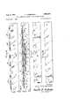
- FIG. 1 is a perspective of a running rail illustrating two delivery units, according to the invention, each delivery unit comprising a delivery plate and delivery bar;
- FIG. 2 is a section on the line 22 of FIG. 1 taken through a short machine bolt;
- FIG. 3 is a section on the line 3-3 of FIG. 1 taken through a long through bolt
- FIG. 4 is a section on the line 4-4 of FIG. 1 taken through a lubricant supply nipple;
- FIG. 5 is a side elevation of the delivery plate looking at the face which contacts the delivery bar;
- FIG. 6 is a side elevation of the delivery bar looking at the face which contacts the delivery plate;
- FIG. 7 is an elevation of a single reinforcing strap used when two applying units are used, as illustrated in FIG. 1;
- FIG. 8 is a side elevation of a reinforcing strap used when a single applying unit is used
- FIG. 9 is a perspective of a section of delivery bar illustrating the primary longitudinal groove, the secondary longitudinal grooves, and the restricted grooves.
- FIG. l0- is a fragmentary cross section taken on the line 10-10 of FIG. 9 illustrating the different size restricted grooves.
- the running rail is a standard T-rail having base 13, web 14 and head 15. The side of head 15 is cut away to form bevellfi. It will be understood that the number of delivery devices used depends upon the amount of lubricant it is desired to apply to the wheel flanges. Each applying device will be supplied with lubricant by its own single gear pump operated by suitable operating mechanism (not shown).
- Each lubricant applying device comprises, in general, a delivery or D-bar 11 and a delivery plate 12 suitably clamped together and to the running rail 10.
- the clamped plates provide branched distributing ducts (FIGS. 2 and 4) to deliver lubricant to a deep accumulating and applying slot 28; slot 28 is formed by a bevel on the delivery plate 12 and by the bevel '16 on rail head 15.
- the applying slot 28 applies lubricant to the flanges 17 of railway wheels, as indicated particularly in FIG. 2.
- the delivery bar 11 has a longitudinal primary groove 20 having an enlarged mid-point 19.
- Bar 11 also has two longitudinal secondary grooves 21.
- the secondary grooves 21 are connected end-to-end to form a single groove, but may be considered, for purposes of explanation, as two separate grooves.
- the mid-point of each secondary groove 21 is connected to the end of the primary groove 20 by a junction groove 22.
- Delivery bar 11 also has a number of vertical restricted slots 23 and 24 connecting secondary grooves 21 with space above the bar.
- these slots 23, 2.4 become, in effect, orifices which feed the deep applying slot 28.
- primary groove 20 is both wider and deeper than secondary groove 21 and that secondary groove 21 is deeper than restricted slots 23 and 24.
- the relation between the cross sections of these ducts will be discussed more at length below.
- the delivery plate 12 has an upper rib 26 having an outer beveled surface 29 and an inner beveled surface forming, with the head bevel 16, the deep slot 28. Delivery plate 12 also has a series of spacers 31 welded thereto which engage the rail head 15 to prevent the applying slot 28 from being closed by pressure of wheel flanges 17. Plate 12 also has openings for the shortbolts '34 and through bolts 35, and an opening 36 for feed nipple 30.
- the delivery bar 11 has a longitudinal back slot 37 facing the rail web, which houses the square heads of the short bolts 34 to keep them from turning.
- through bolts 35 pass through the rail web 14 and through reinforcing strap 38 to clamp the entire assembly together.
- a grease-tight seal between the delivery plate 12 and delivery bar 11 is obtained by having smooth meeting surfaces and applying a light coat of plastic sealing compound to the surfaces. This seal, together with the fact that the two plates are drawn together by a series of short bolts 34 and through bolts 35, prevents any leakage of grease forced through the several branched ducts.
- the nipple 30 is fed with lubricant by a single pump (not shown) of the positive discharge gear type, such as disclosed in Heidenthal Patents 2,059,235 or 2,185,810.
- the operating mechanism (not shown) for driving the pump may be of the type shown in these patents; or, if desired, the operating mechanism for driving the pump may be of the type disclosed in oopending application, Serial No. 729,735, filed April 21, 1958, in the name of Oscar F. Magnus, and assigned to the present assignee.
- the operating mechanism may be mounted on the track in any-convenient or desirable location depending upon the particular operating mechanism and other requirements.
- the reinforcing strap 38 of FIG. 7 is used, which extends substantially the entire length of the two units.
- the shorter strap of FIG. 8 will be used, which extends substantially the length of only one unit.
- Uniform distribution of lubricant along the deep delivery slot 28 depends upon the proportioning of the restricted orifices and the shapes and dimensions of the primary and secondary feed conduits and of the restricted orifices.
- the restricted orifices may be divided into groups indicated by A to F in FIG. 6.
- Center groups B and E adjoining junctions 22 are smaller in cross section; whereas end groups A and C, on the one hand, and D and F, on the other, remote from junctions 22, are of larger cross section.
- Center groups B and E each contain eight orifices and end groups A, C, D and F each contain seven orifices, making fortyfour orifices in all.
- the restricted orifices are vtapered or wedge shape in cross section, the larger orifices 24 being deeper and wider than the smaller orifices 23.
- the cross sections of the several feed ducts are also important to obtaining uniform lubricant distribution along the length of the applying slot. Taking the cros section of the three-quarter inch nipple 30 as one hundred percent, in practice the cross sectional area of the primary groove 20 was taken at'about thirty-four percent and since the lubricant moves in both directions from the mid-point, the total effective cross section of both branches of primary groove 20 is sixty-eight percent. The.
- cross section of the secondary grooves 21 was reduced to about sixteen percent of the original nipple, and since the lubricant moves in two directions from each junction point 22, the total effective cross sectional areas of the four branches of the secondary grooves.21 amounted to sixty-four percent of the cross section of the feed nipple this is slightly less than the total efiective cross section of the primary grooves 20.
- the accumulating slot 28 is deliberately made deep s as to act as a sort of storage or accumulation space. Thir depth, together with the angularity between the orifi 23, 24 and the side of the rail head absorbs the s of lubricant from the restricted orifices 23, 24 and -pre vents them from squirting the lubricant too far where the lubricant can get on the wheel treads.
- the accurnulation slot 28 thus retards or absorbs the squirts, preventing them from reaching the wheel treads and at the same time permits a certain longitudinal flow of lubricant, length-Y Wise of the rail, to equalize the feed along the length of the delivery slot. The lubricant oozes from the top of the slot 28 where it is picked up by the passing wheel flange 17 in a long thin line.
- a rail lubricant delivery applying device which is simple in construction and reliable in operation. It distributes the lubricant evenly and uniformly along the longitudinal delivery and applying slot.
- the delivery device applies the lubricant in a long thin line to the wheel flanges without any danger of getting the lubricant on the wheel treads in spite of the squirting action of the restricted orifices.
- the invention also reduces the amount of external branch piping and need for machining the running rail.
- a running T-rail a delivery bar member adjacent the rail web, a delivery plate member fitting against said bar member and having an upper rib forming, with the rail head, a deep lubricant accumulation and applying slot, the meeting surface of at least one of said members containing a primary longitudinal duct, a set of secondary longitudinal ducts above said primary duct, junction ducts at the ends of said primary duct, each junction duct connecting the primary duct with the midpoint of its respective secondary duct, a series of upright restricted orifice ducts connecting said secondary ducts with said accumulation slot, and feed means communicating with the mid-point of said primary duct.
- a running T-rail having a beveled surface at the under corner of its head, a D-bar adjacent the rail web and fitting the upper fillet of the rail, said D-bar having an upright face registering with the lower edge of said beveled surface, a delivery plate fitting against said D-bar and having an upper rib whose inner fiace carries a beveled surface to form, with said head beveled surface, a deep accumulation slot, said rib having a beveled outer surface to clear wheel flanges; said D-bar having a primary longitudinal groove, a set of aligned secondary longitudinal grooves above said primary groove, junction grooves at the ends of said primary groove, each junction groove connecting the primary groove with the mid-point of its respective secondary groove, a series of upright restricted orifices connecting said secondary grooves with said accumulation slot, those restricted orifices near said junction grooves being of smaller cross section than those remote firom said junction grooves; said delivery plate having a feed opening communicating with the mid-point of said
Landscapes
- Engineering & Computer Science (AREA)
- Mechanical Engineering (AREA)
- Coating Apparatus (AREA)
Description
RAIL LUBRICATOR DELIVERY AND APPLYING DEVICE Filed July l, 1958 Aug. 8, 1961 J. STEMBERGER 4 Sheets-Sheet 1 INVENTOR. JOHN STEM BERGER HTTOENE f RAIL LUBRICATOR DELIVEFY AND APPLYING DEVICE Filed July 1. 1958 Aug. 8, 1961 .1. STEMBERGER 4 Sheets-Sheet 2 m W 3 w A r g w .8 s. a k v 8 8 k a m x 3 kn l mu: .IJ-.M....,. W .1 .L L &
9N QN v Q mE RMUVO E T WJT S 0 MM 1961 J. STEMBERGER- 2,995,210
RAIL LUBRICATOR DELIVERY AND APPLYING DEVICE Filed July 1, 1958 4 Sheets-Sheet 3 United States Patent Ofiiice 2,995,210 Patented Aug. 8, 1961 2 995 RAIL LUBRICATOR DELIVERY AND APPLYING The invention relates to lubricating devices for railway rails and more particularly of the type shown in Heiden- {hal Patent 2,185,810, dated January 2, 1940, although not limited to such use.
Rail lubricators of the Heidenthal type have been in commercial use for many years and have given generally satisfactory service. These devices comprise a wheeloperated ramp on the running rail driving a series of lubricant gear pumps located in the bottom of the lubricant reservoir alongside the track. The pumps feed lubricant to a lubricant delivery or applying device mounted on the gauge side of the running rail, which delivers lubricant to the wheel flanges in a long substantially continuous thin line.
The prior delivery device comprises essentially a series-- of lubricant chambers adjacent the rail web, which chambers deliver the lubricant through a substantially continuous longitudinal delivery slot formed between a bevel on the cut-away rail head and a delivery member bolted to the rail. Each pump feeds two adjacent lubricant chambers through an externally branched piping sys tem. Each chamber is provided with a special equalizing rib to equalize the lubricant feed to its respective delivery slot.
Objects of the present invention are to improve the uniformity of lubricant feed to the delivery and applying slot, to reduce the amount of external branched'piping, and in general, to simplify the lubricant feedto the delivery and applying devices.
According to a preferred form of the present invention, a delivery bar and delivery plate are bolted together and to the rail. The delivery bar is provided with a primary-longitudinal groove to whose mid-point the pump delivers lubricant; 'the delivery bar is also provided with a pair of aligned secondary longitudinal grooves whose mid-points are connected by junctions to the ends of the primary groove.
Connecting with the secondary grooves at the top edge of the bar are two sets of special grooves of restricted cross section. Each set of special grooves comprises a center group of smaller cross section adjoining itsparticular junction, and end groups of; larger cross section on either side. The delivery plate has an upper longitudinal rib with a beveled inner face which forms, with the bevel on the rail head, a deep accumulation and applying slot. This upper rib also has a beveled outer face to clear the wheel flange.
The several grooves" are so shaped and proportioned that, when the pump is operated to force lubricant to the delivery device, the lubricant is squirted through the restricted orifices, formed by the restricted grooves and delivery plate, into the deep accumulation slot where the lubricant builds up and finally oozes out, and from which it is wiped ofl by the wheel flanges in a substantially continuous long thin line.
Other objects and features of the invention will be more apparent from the following description and claims when considered with the accompanying drawings in which:
FIG. 1 is a perspective of a running rail illustrating two delivery units, according to the invention, each delivery unit comprising a delivery plate and delivery bar;
FIG. 2 is a section on the line 22 of FIG. 1 taken through a short machine bolt;
FIG. 3 is a section on the line 3-3 of FIG. 1 taken through a long through bolt;
FIG. 4 is a section on the line 4-4 of FIG. 1 taken through a lubricant supply nipple;
FIG. 5 is a side elevation of the delivery plate looking at the face which contacts the delivery bar;
FIG. 6 is a side elevation of the delivery bar looking at the face which contacts the delivery plate;
FIG. 7 is an elevation of a single reinforcing strap used when two applying units are used, as illustrated in FIG. 1;
FIG. 8 is a side elevation of a reinforcing strap used when a single applying unit is used;
FIG. 9 is a perspective of a section of delivery bar illustrating the primary longitudinal groove, the secondary longitudinal grooves, and the restricted grooves; and
FIG. l0-is a fragmentary cross section taken on the line 10-10 of FIG. 9 illustrating the different size restricted grooves.
In the following description and in the claims, various details will be identified by specific names for convenience, but they are intended to be as generic in their application as the art will permit.
Like reference characters denote like parts in the several figures of the drawings.
In the accompanying drawings and in the description forming part of this specification, certain specific disclosure of the invention is made for purposes of explanation, but it will be understood that the details may be modified in various respects without departure from the broad aspect of the invention.
Referring now to the drawings and more particularly to FIG. 1, two lubricant delivery or applying devices 8 and 9 are shown applied to running rail 10. The running rail is a standard T-rail having base 13, web 14 and head 15. The side of head 15 is cut away to form bevellfi. It will be understood that the number of delivery devices used depends upon the amount of lubricant it is desired to apply to the wheel flanges. Each applying device will be supplied with lubricant by its own single gear pump operated by suitable operating mechanism (not shown).
Since the lubricant applying devices 8 and 9 are identical, it is only necessary to describe one. Each lubricant applying device comprises, in general, a delivery or D-bar 11 and a delivery plate 12 suitably clamped together and to the running rail 10. The clamped plates provide branched distributing ducts (FIGS. 2 and 4) to deliver lubricant to a deep accumulating and applying slot 28; slot 28 is formed by a bevel on the delivery plate 12 and by the bevel '16 on rail head 15. The applying slot 28 applies lubricant to the flanges 17 of railway wheels, as indicated particularly in FIG. 2.
Referring now to FIGS. 6, 9 and 10, the delivery bar 11 has a longitudinal primary groove 20 having an enlarged mid-point 19. Bar 11 also has two longitudinal secondary grooves 21. The secondary grooves 21 are connected end-to-end to form a single groove, but may be considered, for purposes of explanation, as two separate grooves. The mid-point of each secondary groove 21 is connected to the end of the primary groove 20 by a junction groove 22.
It will be noted that primary groove 20 is both wider and deeper than secondary groove 21 and that secondary groove 21 is deeper than restricted slots 23 and 24. The relation between the cross sections of these ducts will be discussed more at length below.
Referring also to FIG. 5, the delivery plate 12 has an upper rib 26 having an outer beveled surface 29 and an inner beveled surface forming, with the head bevel 16, the deep slot 28. Delivery plate 12 also has a series of spacers 31 welded thereto which engage the rail head 15 to prevent the applying slot 28 from being closed by pressure of wheel flanges 17. Plate 12 also has openings for the shortbolts '34 and through bolts 35, and an opening 36 for feed nipple 30.
The delivery bar 11 has a longitudinal back slot 37 facing the rail web, which houses the square heads of the short bolts 34 to keep them from turning. In addition to the short bolts 34, through bolts 35 pass through the rail web 14 and through reinforcing strap 38 to clamp the entire assembly together.
It will be understood that a grease-tight seal between the delivery plate 12 and delivery bar 11 is obtained by having smooth meeting surfaces and applying a light coat of plastic sealing compound to the surfaces. This seal, together with the fact that the two plates are drawn together by a series of short bolts 34 and through bolts 35, prevents any leakage of grease forced through the several branched ducts.
The nipple 30 is fed with lubricant by a single pump (not shown) of the positive discharge gear type, such as disclosed in Heidenthal Patents 2,059,235 or 2,185,810. The operating mechanism (not shown) for driving the pump may be of the type shown in these patents; or, if desired, the operating mechanism for driving the pump may be of the type disclosed in oopending application, Serial No. 729,735, filed April 21, 1958, in the name of Oscar F. Magnus, and assigned to the present assignee. The operating mechanism may be mounted on the track in any-convenient or desirable location depending upon the particular operating mechanism and other requirements.
Since two applying devices 8 and 9 are illustrated, the reinforcing strap 38 of FIG. 7 is used, which extends substantially the entire length of the two units. In the event only one applying device is used, the shorter strap of FIG. 8 will be used, which extends substantially the length of only one unit.
Uniform distribution of lubricant along the deep delivery slot 28 depends upon the proportioning of the restricted orifices and the shapes and dimensions of the primary and secondary feed conduits and of the restricted orifices.
Referring to FIGS. 6, 9 and 10, the restricted orifices may be divided into groups indicated by A to F in FIG. 6. Center groups B and E adjoining junctions 22 are smaller in cross section; whereas end groups A and C, on the one hand, and D and F, on the other, remote from junctions 22, are of larger cross section. Center groups B and E each contain eight orifices and end groups A, C, D and F each contain seven orifices, making fortyfour orifices in all. As shown particularly in FIGS. 9 and 10, the restricted orifices are vtapered or wedge shape in cross section, the larger orifices 24 being deeper and wider than the smaller orifices 23.
It will be understood that the number of restricted orifices 2'3, 24, their actual cross section, and the number of different cross sections may be varied, and still obtain desirable results.
In practice, excellent results have been obtained using only two sizes of orifices and with the number and arrangement illustrated. The smaller restricted wedgeshape orifices 23 were made .027 inch deep while the larger restricted orifices 24 were made .037 inch deep, with corresponding difference in width. In each case depth was measured from the surface of the bar 11 to the bottom of the grooves as indicated by X in 'FIG. 10. The angle of the wedge was 45 with respect to the center line Y of the wedge. The orifices were about one inch apart, from center to center.
The cross sections of the several feed ducts are also important to obtaining uniform lubricant distribution along the length of the applying slot. Taking the cros section of the three-quarter inch nipple 30 as one hundred percent, in practice the cross sectional area of the primary groove 20 was taken at'about thirty-four percent and since the lubricant moves in both directions from the mid-point, the total effective cross section of both branches of primary groove 20 is sixty-eight percent. The. cross section of the secondary grooves 21 was reduced to about sixteen percent of the original nipple, and since the lubricant moves in two directions from each junction point 22, the total effective cross sectional areas of the four branches of the secondary grooves.21 amounted to sixty-four percent of the cross section of the feed nipple this is slightly less than the total efiective cross section of the primary grooves 20.
The total effective cross sectional area of all forty-four restricted orifices of groups .A to F amounted to about sixteen percent of the cross section of the nipple, or onequarter of the total effective cross sectional area of the secondary grooves 21. This considerable reduction in area causes the lubricant to flow through the restricted orifices 23, 24 at a higher speed. It has been found that if the lubricant is not forced through these orifices quickly, the flow has a tendency to become sluggish and thedistribution uneven. 7
The accumulating slot 28 is deliberately made deep s as to act as a sort of storage or accumulation space. Thir depth, together with the angularity between the orifi 23, 24 and the side of the rail head absorbs the s of lubricant from the restricted orifices 23, 24 and -pre vents them from squirting the lubricant too far where the lubricant can get on the wheel treads. The accurnulation slot 28 thus retards or absorbs the squirts, preventing them from reaching the wheel treads and at the same time permits a certain longitudinal flow of lubricant, length-Y Wise of the rail, to equalize the feed along the length of the delivery slot. The lubricant oozes from the top of the slot 28 where it is picked up by the passing wheel flange 17 in a long thin line.
It will be understood that the velocity of flow of lubricant from the nipple -30 to the restricted orifices 23, 24- progressively increases, reaching a maximum velocity through the restricted orifices. Also, that the single gear type pump, which feeds the nipple with lubricant, is sulfi- 'ciently.large, and that the operating mechanism, which operates the pump, is sufliciently powerful to cause the desired velocity through the restricted orifices 23, 24. It will be understood that the operating mechanism, operated by the passage of car wheels, operates the pump inter- .mittently so that the lubricant is delivered to nipple 30 in a series of pulses.
Thus a rail lubricant delivery applying device is pro-' vided which is simple in construction and reliable in operation. It distributes the lubricant evenly and uniformly along the longitudinal delivery and applying slot. The delivery device applies the lubricant in a long thin line to the wheel flanges without any danger of getting the lubricant on the wheel treads in spite of the squirting action of the restricted orifices. The invention also reduces the amount of external branch piping and need for machining the running rail.
While certain novel features of the invention have been disclosed herein, and are pointed out in the annexed claims, it will be understood that various omissions, substitutions and changes may be made by those skilled in the art without departing from the spirit of the invention.
What is claimed is:
1. In a rail lubricator, a running T-rail, a delivery bar member adjacent the rail web, a delivery plate member fitting against said bar member and having an upper rib forming, with the rail head, a deep lubricant accumulation and applying slot, the meeting surface of at least one of said members containing a primary longitudinal duct, a set of secondary longitudinal ducts above said primary duct, junction ducts at the ends of said primary duct, each junction duct connecting the primary duct with the midpoint of its respective secondary duct, a series of upright restricted orifice ducts connecting said secondary ducts with said accumulation slot, and feed means communicating with the mid-point of said primary duct.
2. In the rail lubricator of claim 1, a series of blocks located in said applying slot and spaced along the length thereof, said blocks being secured to a wall of said applying slot and acting to prevent car wheels from closing said slot.
3. In a rail lubricator, a running T-rail having a beveled surface at the under corner of its head, a D-bar adjacent the rail web and fitting the upper fillet of the rail, said D-bar having an upright face registering with the lower edge of said beveled surface, a delivery plate fitting against said D-bar and having an upper rib whose inner fiace carries a beveled surface to form, with said head beveled surface, a deep accumulation slot, said rib having a beveled outer surface to clear wheel flanges; said D-bar having a primary longitudinal groove, a set of aligned secondary longitudinal grooves above said primary groove, junction grooves at the ends of said primary groove, each junction groove connecting the primary groove with the mid-point of its respective secondary groove, a series of upright restricted orifices connecting said secondary grooves with said accumulation slot, those restricted orifices near said junction grooves being of smaller cross section than those remote firom said junction grooves; said delivery plate having a feed opening communicating with the mid-point of said primary groove.
4. In the rail lubricator of claim 3, said restricted orifices being tapered in cross section.
References Cited in the file of this patent UNITED STATES PATENTS
Priority Applications (1)
| Application Number | Priority Date | Filing Date | Title |
|---|---|---|---|
| US745891A US2995210A (en) | 1958-07-01 | 1958-07-01 | Rail lubricator delivery and applying device |
Applications Claiming Priority (1)
| Application Number | Priority Date | Filing Date | Title |
|---|---|---|---|
| US745891A US2995210A (en) | 1958-07-01 | 1958-07-01 | Rail lubricator delivery and applying device |
Publications (1)
| Publication Number | Publication Date |
|---|---|
| US2995210A true US2995210A (en) | 1961-08-08 |
Family
ID=24998667
Family Applications (1)
| Application Number | Title | Priority Date | Filing Date |
|---|---|---|---|
| US745891A Expired - Lifetime US2995210A (en) | 1958-07-01 | 1958-07-01 | Rail lubricator delivery and applying device |
Country Status (1)
| Country | Link |
|---|---|
| US (1) | US2995210A (en) |
Cited By (7)
| Publication number | Priority date | Publication date | Assignee | Title |
|---|---|---|---|---|
| FR2670167A1 (en) * | 1990-12-05 | 1992-06-12 | Brincourt Guy | Device for depositing a substantially fluid material in a given zone of the lateral surface of rails |
| US5394958A (en) * | 1992-12-22 | 1995-03-07 | Portec Inc. | Rail lubrication apparatus |
| US5641037A (en) * | 1995-06-06 | 1997-06-24 | Portec, Inc., R M P Division | Rail lubrication apparatus |
| US5722509A (en) * | 1996-05-14 | 1998-03-03 | Consolidated Rail Corporation | Flange oiler |
| US6719095B2 (en) * | 2000-09-22 | 2004-04-13 | Lincoln Industrial Corporation | Railroad track lubrication and monitoring thereof |
| GB2433538A (en) * | 2005-12-22 | 2007-06-27 | Multiclip Co Ltd | Lubricating rail joints |
| US10358152B2 (en) * | 2015-08-28 | 2019-07-23 | Loram Maintenance Of Way, Inc. | Method and apparatus for gauge-face lubrication |
Citations (7)
| Publication number | Priority date | Publication date | Assignee | Title |
|---|---|---|---|---|
| US1728412A (en) * | 1927-07-16 | 1929-09-17 | Albert G Humphries | Track lubricator |
| US1918146A (en) * | 1932-11-02 | 1933-07-11 | Ardco Mfg Company | Rail and wheel flange lubricator |
| US2016975A (en) * | 1933-09-29 | 1935-10-08 | Ardco Mfg Company | Rail flange lubricator |
| US2047600A (en) * | 1931-05-29 | 1936-07-14 | Ardco Mfg Company | Rail flange lubricator |
| US2077077A (en) * | 1935-10-31 | 1937-04-13 | Ardco Mfg Company | Lubricating device for railways |
| US2170917A (en) * | 1935-07-11 | 1939-08-29 | Ardco Mfg Co | Rail lubricating device |
| US2884093A (en) * | 1956-07-05 | 1959-04-28 | John K Stewart | Rail lubricators |
-
1958
- 1958-07-01 US US745891A patent/US2995210A/en not_active Expired - Lifetime
Patent Citations (7)
| Publication number | Priority date | Publication date | Assignee | Title |
|---|---|---|---|---|
| US1728412A (en) * | 1927-07-16 | 1929-09-17 | Albert G Humphries | Track lubricator |
| US2047600A (en) * | 1931-05-29 | 1936-07-14 | Ardco Mfg Company | Rail flange lubricator |
| US1918146A (en) * | 1932-11-02 | 1933-07-11 | Ardco Mfg Company | Rail and wheel flange lubricator |
| US2016975A (en) * | 1933-09-29 | 1935-10-08 | Ardco Mfg Company | Rail flange lubricator |
| US2170917A (en) * | 1935-07-11 | 1939-08-29 | Ardco Mfg Co | Rail lubricating device |
| US2077077A (en) * | 1935-10-31 | 1937-04-13 | Ardco Mfg Company | Lubricating device for railways |
| US2884093A (en) * | 1956-07-05 | 1959-04-28 | John K Stewart | Rail lubricators |
Cited By (8)
| Publication number | Priority date | Publication date | Assignee | Title |
|---|---|---|---|---|
| FR2670167A1 (en) * | 1990-12-05 | 1992-06-12 | Brincourt Guy | Device for depositing a substantially fluid material in a given zone of the lateral surface of rails |
| US5394958A (en) * | 1992-12-22 | 1995-03-07 | Portec Inc. | Rail lubrication apparatus |
| US5641037A (en) * | 1995-06-06 | 1997-06-24 | Portec, Inc., R M P Division | Rail lubrication apparatus |
| US5722509A (en) * | 1996-05-14 | 1998-03-03 | Consolidated Rail Corporation | Flange oiler |
| US6719095B2 (en) * | 2000-09-22 | 2004-04-13 | Lincoln Industrial Corporation | Railroad track lubrication and monitoring thereof |
| GB2433538A (en) * | 2005-12-22 | 2007-06-27 | Multiclip Co Ltd | Lubricating rail joints |
| US10358152B2 (en) * | 2015-08-28 | 2019-07-23 | Loram Maintenance Of Way, Inc. | Method and apparatus for gauge-face lubrication |
| US10994757B2 (en) * | 2015-08-28 | 2021-05-04 | Loram Maintenance Of Way, Inc. | Method and apparatus for gauge-face lubrication |
Similar Documents
| Publication | Publication Date | Title |
|---|---|---|
| US2995210A (en) | Rail lubricator delivery and applying device | |
| DE2264827B2 (en) | Device for treating and / or processing the surface of a workpiece | |
| US3147822A (en) | Rail and flange lubricating apparatus | |
| EP0010269B1 (en) | Process and apparatus for splitting a stream of lubricant droplets in a carrying medium into at least two separate outgoing flows | |
| DE2320158A1 (en) | TRANSPORT EQUIPMENT | |
| DE19700028C2 (en) | Device for the continuous production of flexible plastic corrugated pipes in corrugated pipe forming machines | |
| DE6912437U (en) | ALL SIDE ROLLER FOR ALL SIDE ROLLER CONVEYORS | |
| DE863953C (en) | Hydraulically operated feed device, especially for conveyor wagons in mining operations | |
| RU97104884A (en) | DEVICE FOR COATING PROCESSED GOODS BY PAINT BY SPRAYING | |
| US2185810A (en) | Rail lubricator | |
| US1880672A (en) | Wheel flange oiler | |
| EP0293399A1 (en) | Guiding rail and link chain for chain saws. | |
| USRE29493E (en) | Cable cleaning units | |
| DE2535151C3 (en) | Fifth wheel for road vehicles | |
| DE202007005930U1 (en) | Device for dividing a lubricant flow conveyed by means of a gas flow | |
| AT400427B (en) | STATIONARY LUBRICATION SYSTEM | |
| DE1926915A1 (en) | Rotary feeder for feeding in waste material | |
| DE19804419A1 (en) | Machine precision interface for two linear motion machine parts | |
| US3581844A (en) | Veneer lathe oiler | |
| DE9319684U1 (en) | Locomotive device for driving through tubular channels or the like. | |
| DE3736580A1 (en) | BEAM TRACK BRAKE FOR BRAKING RAILWAYS | |
| US3709268A (en) | Drum barker | |
| US2145067A (en) | Wheel flange oiler | |
| US1342605A (en) | Lubricating apparatus | |
| DE1208692B (en) | Storage device for pneumatic tube boxes, in particular large pneumatic tube containers |