US2984426A - Continuous roll winder - Google Patents
Continuous roll winder Download PDFInfo
- Publication number
- US2984426A US2984426A US737311A US73731158A US2984426A US 2984426 A US2984426 A US 2984426A US 737311 A US737311 A US 737311A US 73731158 A US73731158 A US 73731158A US 2984426 A US2984426 A US 2984426A
- Authority
- US
- United States
- Prior art keywords
- roll
- rolls
- web
- winding
- drum
- Prior art date
- Legal status (The legal status is an assumption and is not a legal conclusion. Google has not performed a legal analysis and makes no representation as to the accuracy of the status listed.)
- Expired - Lifetime
Links
Images


Classifications
-
- B—PERFORMING OPERATIONS; TRANSPORTING
- B65—CONVEYING; PACKING; STORING; HANDLING THIN OR FILAMENTARY MATERIAL
- B65H—HANDLING THIN OR FILAMENTARY MATERIAL, e.g. SHEETS, WEBS, CABLES
- B65H19/00—Changing the web roll
- B65H19/22—Changing the web roll in winding mechanisms or in connection with winding operations
- B65H19/2238—The web roll being driven by a winding mechanism of the nip or tangential drive type
-
- B—PERFORMING OPERATIONS; TRANSPORTING
- B65—CONVEYING; PACKING; STORING; HANDLING THIN OR FILAMENTARY MATERIAL
- B65H—HANDLING THIN OR FILAMENTARY MATERIAL, e.g. SHEETS, WEBS, CABLES
- B65H19/00—Changing the web roll
- B65H19/22—Changing the web roll in winding mechanisms or in connection with winding operations
- B65H19/26—Cutting-off the web running to the wound web roll
-
- Y—GENERAL TAGGING OF NEW TECHNOLOGICAL DEVELOPMENTS; GENERAL TAGGING OF CROSS-SECTIONAL TECHNOLOGIES SPANNING OVER SEVERAL SECTIONS OF THE IPC; TECHNICAL SUBJECTS COVERED BY FORMER USPC CROSS-REFERENCE ART COLLECTIONS [XRACs] AND DIGESTS
- Y10—TECHNICAL SUBJECTS COVERED BY FORMER USPC
- Y10T—TECHNICAL SUBJECTS COVERED BY FORMER US CLASSIFICATION
- Y10T83/00—Cutting
- Y10T83/364—By fluid blast and/or suction
-
- Y—GENERAL TAGGING OF NEW TECHNOLOGICAL DEVELOPMENTS; GENERAL TAGGING OF CROSS-SECTIONAL TECHNOLOGIES SPANNING OVER SEVERAL SECTIONS OF THE IPC; TECHNICAL SUBJECTS COVERED BY FORMER USPC CROSS-REFERENCE ART COLLECTIONS [XRACs] AND DIGESTS
- Y10—TECHNICAL SUBJECTS COVERED BY FORMER USPC
- Y10T—TECHNICAL SUBJECTS COVERED BY FORMER US CLASSIFICATION
- Y10T83/00—Cutting
- Y10T83/647—With means to convey work relative to tool station
- Y10T83/6584—Cut made parallel to direction of and during work movement
- Y10T83/6592—Interrelated work-conveying and tool-moving means
- Y10T83/6595—With means to move tool laterally of feed direction during cutting
-
- Y—GENERAL TAGGING OF NEW TECHNOLOGICAL DEVELOPMENTS; GENERAL TAGGING OF CROSS-SECTIONAL TECHNOLOGIES SPANNING OVER SEVERAL SECTIONS OF THE IPC; TECHNICAL SUBJECTS COVERED BY FORMER USPC CROSS-REFERENCE ART COLLECTIONS [XRACs] AND DIGESTS
- Y10—TECHNICAL SUBJECTS COVERED BY FORMER USPC
- Y10T—TECHNICAL SUBJECTS COVERED BY FORMER US CLASSIFICATION
- Y10T83/00—Cutting
- Y10T83/869—Means to drive or to guide tool
- Y10T83/8821—With simple rectilinear reciprocating motion only
- Y10T83/8822—Edge-to-edge of sheet or web [e.g., traveling cutter]
Landscapes
- Replacement Of Web Rolls (AREA)
- Winding Of Webs (AREA)
Description
y 16, 1961 R. MCNEAMAN JOHNSON 2,984,426
CONTINUOUS ROLL WINDER 5 Sheets-Sheet 1 Filed May 23, 1958 Rube! Mc/Vemm z c/b/msan y 16, 1961 R. MCNEAMAN JOHNSON 2,984,425
commons ROLL WINDER Filed May 23, 1958 5 Sheets-Sheet 2 Fube/ McA/eamazz Johnson Z7 1 W W EH 5 y 1961 R. MCNEAMAN JOHNSON CONTINUOUS ROLL WINDER 5 Sheets-Sheet 3 Filed May 23, 1958 he EZ'UT Eube/ Mc/Veaman Johnson 9 R R E M RL Tx ME n Hum m M M n w n mum M NW am a a WM mm M m. H m W N WTSM. 5 H a 3 y 1951 R. MCNEAMAN JOHNSON ,984,426
CONTINUOUS ROLL WINDER 5 Sheets-Sheet 4 Filed May 25, 1958 he afar .Pubel Mc/Veman :Mmsan y- 1961 R. MCNEAMAN JOHNSON 2,984,426
commuous ROLL WINDER Filed May 25, 1958 5 Sheets-Sheet 5 lU-V a 22212: I Rube! Mc/Veamazq Johns on -%$M WWW 5177775 CONTINUOUS ROLL WINDER Rubel McNeaman Johnson, Rte. 2, Box 25, Crossett, Arlr.
Filed May 23, 1958, Ser. No. 737,311
Claims. (Cl. 242-56) The present invention relates to improvements in winding machines, and particularly to an improved automatic winding machine for sequentially winding rolls from a continuous supply web of material.
An object of the invention is to provide an improved roll winding machine well suited for winding rolls of paper or the like, which is well adapted to high speed winding and makes possible smooth transition from roll to roll, and provides an improved transfer of the winding web automatically from a completed roll to a succeeding core.
Another object of the invention is to provide an apparatus for winding continuous web material on separate successive rolls with use only of smoothly rotating members with fluid cushioned movements, and wherein controlled hardness of the rolls is obtainable in a completely automatic machine.
A further object of the invention is to provide a winding machine of the character described wherein the functions of discharging a wound roll and replacing it with a fresh core, the ejecting of a completed roll, and the driving of the core in controlled rotation are enhanced to obtain an improved winding machine.
The present invention contemplates providing a winding drum with a plurality of parallel annularly arranged riding rolls carried on a reel positioned above the drum and operative to successively bring fresh cores into a winding nest between the drum and rolls and to eject finished rolls. A feature of the invention is the provision of a plurality of rider rolls which are driven continuously to rotate the cores and to create a force which tends to take up any backlash in the mechanism for indexing the reel carrying the rolls. The core being wound is caged between a pair of rider rolls and the drum, and when a wound core reaches a predetermined size, slightly less than the finished size, the reel indexes to carry the wound core over the surface of the drum to the position from which it is to be eased onto the receiving rack which is provided for receiving finished rolls. During the indexing operation the roll of paper is held in the winding nest by a holding roll. At the same time, the indexing of the reel also brings a fresh core into position ready to receive the web for starting a new roll of paper. By the time the indexing operation is completed, the roll of paper is built to full size and the transfer operation begins and proceeds as follows. A slitter knife engages the moving web to cut a narrow strip along the edge. The narrow strip is separated by a blasting device which carries the separated end of the strip around a fresh core. The knife then moves across the broad remaining portion of the web to sever it. When the transfer of the web to the fresh core is completed, the finished roll is eased from the winding nest onto the receiving rack. Both the drum and the rider rolls are driven continuously with all of the rider rolls being rotated during machine operation. A variable speed drive controls the relative speeds of rotation to control the hardness of the wound roll. A
j States Fatent ice pressure control device controls the weight applied by the reel of rider rolls against a core being wound.
Other features and objects will become apparent with the teachings of the principles of the invention in connection with the disclosure of the preferred embodiments thereof in the specification, claims and drawings, in which:
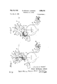
Figure 1 is an end elevational view shown in diagrammatic form of a winding machine constructed in accordance with the principles of the present invention;
Figures 2, 3 and 4 are end elevational views in diagrammatic form similar to Figure 1, and illustrating the position of the parts in successive stages of winding operation, and especially as related to the automatic ejection of a wound roll and the replacement of a fresh core;
Figure 5 is a schematic showing of the arrangement of the control wiring for the machine for obtaining automatic operation;
Figure 6 is a sectional view taken along line VI-VI of Figure 2, and illustrating a cutter mechanism for cutting the web;
Figure 7 is an enlarged sectional view taken along line VII-VII of Figure 3, and illustrating the details of a blasting device for cutting a strip formed in the web;
Figure 8 is an end elevational view of the complete mechanism with parts removed and parts broken away for clarity; and,
Figure 9 is a front elevational view of the machine with the center portions of the rolls removed and with other parts omitted for drawing clarity.
As shown on the drawings:
As illustrated in Figure l, a roll 10 is being completed and will soon be ejected from the machine. The roll is caged between a winding drum 12, and a pair of rider rolls 14 and 16, and rotates in a winding nest 18.
The rider rolls 14 and 16 are carried in a cluster with additional rolls 20, 22, 24 and 26 being shown. The rider rolls are annularly disposed and parallel to each other, being carried on a reel 28. The entire cluster of rider rolls rides on top of the roll 10 being wound. The reel 28 is carried on an arm 30, on one side of the machine, as shown in Figures 1-4, and it will be understood that another carrying arm is provided at the other side of the machine, as will later become clear. The downward pressure of the rolls is controlled by a mechanism which will be described later in connection with the detailed drawings of Figures 8 and 9.
A supply strip 38 of web material is carried over the surface of the drum 12 to be wound on the roll 10. The web will pass under a roll 40, and when the machine changes rolls, the web is acted on by a cutter 42 or a slitter, as will be described.
When the roll 10 reaches the desired size, a switch 46 is actuated by a member 44 on the reel. This initiates the actuation of automatic mechanism for changing rolls. While the indexing changing cycle is shown triggered by a switch which is responsive to the size of the roll being wound, other means may be employed and the machine may be indexed manually, by the position of the cluster of rider rolls, or by the arm 30 carrying the reels, by a timing device set to correspond with the speed of the drum or rolls, by a torque device responsive to the drive for the rider rolls or the drum, or other means as will be appreciated by those skilled in the art.
The switch 46 is also shown in Figure 5 as closing a circuit formed by electrical leads 48 to a sequential control timer 50. The timer will operate the various actuating mechanisms in the proper sequence, as will be observed with the description of the sequence of events.
The reel 28 first indexes in a clockwise direction to the position shown in Figure 2 rolling the wound roll over the top of the surface of the drum 12 to engage a hold back roll 52. The roll 10 continues to wind the web until the material is cut to start on a new roll. The wound roll 10 will then be eased onto racks 54 by the holding roll being released to move from the solid line positions of Figures 1 and 3 to the dotted line position of Figure 4. For this purpose, the holding roll is mounted on pivotal arms 55 and 57, which are controlled in a manner which will be described in connection with Figures 8 and 9.
Referring again to Figure 2, when the reel 28 indexes, the slitter 42 will operate by moving a slitter knife 56 into the web 38.
As illustrated in Figures 1, 2 and 6, the slitter knife 56 is mounted in free trailing fashion with the knife having a rigid back 53 carried on a vertical spindle 58 which is freely pivotal in a bearing 59 on a laterally sliding sleeve 60. The sleeve slides on a squared rod 66. The rod is pivoted by a crank 67 at its end to move the knife between non-cutting position, as shown in Fig. l, and cutting position, as shown in Fig. 2. The sleeve is moved laterally along the rod by suitable mechanism to obtain the lateral cut 62. The free trailing mounting for the blade accommodates cutting along the web length or laterally thereof. The sleeve is controllably moved laterally along the squared rod by a suitable drive, such as by a chain 69 fastened to the sleeve and driven by a drive sprocket 73. The chain 69 pulls the sleeve to move the knife in a direction across the sheet, as shown in Figure 6, with rotation of the sprocket in one direction, and the chain 69 passes over a freely rotatable sprocket 75 and returns the knife with rotation of the drive sprocket 73 in the other direction. The drive sprocket 73 driven by a motor 77, the operation and direction of rotation of which is controlled by a switch 79.
The slitter knife 56 first moves downwardly into the web near the side edge 68 to form a narrow strip 70 along the edge of the web. This narrow strip 70 is severed or broken by a blasting cutter 72, as shown in Figures 3 and 7. The cutter 72 is in the form of a cutting gun having a barrel 74 with a hollow chamber 76 therein. A line 78 leads to the chamber to supply an explosive material, such as a mixture of oxygen and acetylene. The chamber 76 has an open end aligned with an opening '80 in a flange 82 on the drum 12. The gun is provided with an ignition plug 84 which fires the material in the chamber to sever the strip 70. The blast also blows the leading severed end 85, Figure 3, up against the fresh core 36, which is in the winding nest 18. Just prior to cutting the strip 70, a spray of Water is directed against the core 36 by a nozzle 86 to cause the end 85 of the strip to adhere to the fresh core. The slitter knife 56 will be moved transversely across the web 38 along the line 62, as shown in Figure 6, and the strip 70 will be wound on the core to be followed by the entire width of the web. The trailing cut end winds onto the roll 10 which is then lowered onto the rack 54.
Each time the reel 28 indexes, a new core 88 is dropped into an outwardly facing cage from a core rack 90. This may be accomplished by a release pin 92, as illustrated in Figure 4, being withdrawn to drop a core to be carried by the reel.
As illustrated in Figure 5, the series of aforedescribed functions of the machine are inaugurated by operation of the timer sequence control 50, which electrically connects to operate the various machine elements listed in Figure 5 as the Nest Index, Slitter Knife, Spray, Cutter, Slitter Lateral, Holding Roll Release and Core Release. The mechanism for each of the foregoing labeled units will be described in connection with Figures 8 and 9. In most instances, the mechanism is electrically operated,
and labeled squares may be relays or other electrical operating devices for driving the elements. It will be appreciated by those skilled in the art that various other operating devices might be used, such as a cam shaft with actuating switches.
The operating mechanism for the core release 92 is not shown in detail, but may be a solenoid operated trip or the like. Also, the mechanism for operating the slitter knife is not shown in full detail, but, as will be appreciated by those skilled in the art, the pivotal holder for the knife 56 may be rotated by a suitable mechanism such as a rack and pinion, and the sleeve 60 may he slid across the rod 66 by a pinion traveling on a rack or by an elongated cylinder and plunger arrangement or the like, and these details of structure have been omitted for clarity.
Referring to Figures 8 and 9, the machine is supported on a frame. Carried on the frame is a drive shaft 98. The drive shaft is driven by a suitable prime mover, and carries at one end a multi-unit V-belt sheave 188 driving belts 102, which drive a variable pitch sheave 104 that is mounted on a shaft 106 carrying the winding drum 12. The shaft 106 extends across the frame of the machine which includes supporting columns 108 and 110 at each end, mounted on bases 96 and 97 to support the machine on a suitable supporting surface, such as the floor of a manufacturing area.
The drive shaft 98 also is provided with a sprocket 112 driving a chain 114 which drives a spool 115 by drivingly engaging a sprocket 116 on the spool 115. The spool 115 is mounted for free rotation on the end of a reel-carrying shaft 118 and is provided with a sun gear 120 which drives a series of planetary gears that are drivingly connected to the rider rolls. As illustrated in Figure 8, the rider roll 20 is mounted on a shaft 122 which has a planetary gear 124 connected at its end with the planetary gear being driven by the sun gear 120. As illustrated in Figure 9, the sun gear also drives a planetary gear 126 mounted on the end of a shaft 128 which carries the rider roll 22.
Thus the variable pitch sheave 104 can be changed to change the apportionment of total power input between the drum 12 and the rider rolls. For example, an increase in power to the drum will result in a decrease in power to the rider rolls loosening the roll being wound. To tighten the roll, the power delivered to the drum 12 is decreased.
The planetary gear arrangement is enclosed in a housing 129 which is mounted for rotation with the reel shaft 118. The reel 28, at the left end, as shown in Figure 9, is formed of the housing 129 which has a plurality of bearings such as 130 for carrying the shafts, with the bearing 130 being illustrated as carrying the shaft 128. At the other end of the reel shaft 118 is a spider 132 also provided with bearings for carrying the rider roll shafts, and bearing 134 is illustrated as carrying the other end of the shaft 128 for the rider roll 22.
The reel is indexed as a whole by rotating the reel shaft 118. For this purpose, the reel shaft 118 carries a sprocket 136 at its end driven by a chain 138 passing over a drive sprocket 140, which is driven by a motor 142. The motor is electrically operated for short indexing periods by the control mechanism. It will be appreciated by those skilled in the art that other forms of indexing mechanisms may be also expeditiously used.
Extending across between the columns 108 and 110 is a shaft 144 on which arms 55 and 57 are mounted, and which carry at their outer ends the hold-back roll 52. The arms are secured to the shaft to pivot therewith, and the position of the hold-back roll and its shaft 144 is controlled by a crank arm 146 projecting beneath the shaft, in the manner shown in Figures 8 and 9, and connected to a piston rod 148 mounted on a piston slidably located within a cylinder 150. The cylinder may be a pneumatic or hydraulic cylinder controlled through a fluid supply line 152, having an electrically operated flow control valve 154. As the holdback roll 52 is relieved of pressure it eases a wound roll onto the rack 54. This may be done by fiuid permitting to escape from the cylinder 150 through the valve 154 and line 152. Pressurized fluid again directed to the cylinder will move the hold-back roll 52 back into position. It will be appreciated by those skilled in the art that various other forms of control for the hold-back roll 52 may be employed.
The entire cluster of rider rolls carried on the reel 28 rests on the core being wound. The pressure applied by the pair of riding rolls to the core being wound with web material is controlled by cylinders 156 and 158. These cylinders are provided with pistons slidably located therein which have rods 160 and 162 to apply a pressure to the reel 28 to either increase its weight against the roll being wound, or to lift it and decrease the weight. The piston rod 162 is connected to an arm 163 which supports a bearing 164 rotatably carrying the reel shaft 118 for indexing rotation. The piston rod 160 connects to an annular ring 131 supporting the housing 129 in bearings 133 for indexing rotation. The arm 163 and the ring 131 are both mounted for pivotal up and down movement on the drive shaft 98, and permit free controlled movement of the cluster of rider rolls. Fluid pressure lines 166 and 168 lead into the upper ends of the cylinder 156 and 158, and fluid pressure lines 170 and 172 lead into the lower ends of the cylinders. Each of the pressure lines is provided with a control valve with the valves being uniformly operated to control the force applied to the reel. The spider 132 and the housing 129 are each provided with slots for carrying cores between the rider rolls. As illustrated in Figure 9, the spider 132 has a slot 174 to receive the end of the core 36 and the housing 129 has a slot 176 to receive the other end of the core 36. The core may be provided with bearings 178 and 180 at its ends. Means such as a spring loaded detent 182 which is within the slot 184, Figure 8, may be provided for each of the slots to hold the cores in place. It will be appreciated by those skilled in the art that various other core retaining devices might be employed. The slots for the housing 129 to receive the cores are shown at 176, 184, 186, 188, 190 and 192 in Figure 8.
In operation, winding drum 12 and the rider rolls 14, 16, 20, 22, 24 and 26 are all driven in rotation. Thus, the roll 10, which is being wound in the winding nest 18 is driven by the rider rolls 14 and 16, and the winding drum 12. A control in apportionment between the power directed to the drum 12 and directed to the rider rolls can be obtained by the variable pitch sheave 104, thereby controlling the hardness of the wound roll 10. When the Wound roll reaches the desired size, the switch 46 is actuated by the reel 28 being carried upwardly, and the reel is caused to index in a clockwise direction, as illustrated in Figures 1 through 4.
The wound roll 10 is rolled across the top of the drum 12 to the position shown in Figure 2, and the slitter knife 56 enters the web to form the strip 70. This strip is cut by a blast from the cutter 72 which also carries a separated end 85 of the strip onto a fresh core 36. Water is sprayed onto the core 36 to cause the lead end of the strip to adhere thereto. A knife then moves laterally across the web in the path 62, as shown in Figure 6, to separate the rest of the web. The finished roll 10 is then allowed to be eased onto the racks 54 by the release of holding pressure on the hold-rack roll 52.
Thus, it will be seen that I have provided an improved automatic winding mechanism which meets the objectives and advantages hereinbefore set forth. The mechanism is well adapted to high speed automatic roll winding operation. Steps in the automatic sequence are performed without shock and the parts and rolls are eased into position. Control of the functions of the elements is obtained for control of the winding operation and for control of the hardness of the roll. Improved cutting and transfer mechanism is provided for sure rapid change of material from a wound roll to a fresh core.
I have, in the drawings and specification presented a detailed disclosure of the preferred embodiment of my invention, and it is to be understod that I do not intend to limit the invention to the specific forms disclosed, but intend to cover all modifications, changes and alternative constructions and methods falling within the scope of the principles taught by my invention.
I claim as my invention:
1. A winding machine for automatically winding successive rolls from a supply Web comprising a winding nest wherein a core is wound with web material, means for removing wound cores from the nest and for bringing fresh cores into the nest, a slitter positioned in advance of said nest, slitter operating means for moving the slitter into the web adjacent the edge to form a narrow strip and to subsequently move the slitter laterally across the remaining width of the web, an explosive chamber for an explosive material having an opening positioned adjacent a fresh core in said nest, and an igniting means in said chamber for igniting said explosive material to direct an exploded jet of gases through the opening against said narrow strip to separate the strip.
2. A Winding machine for sequentially winding a series of rolls from a continuous supply web which comprises a winding drum, a pair of rider rolls facing said drum and forming a winding cage therebetween, means for rotating a core in the cage to be wound with a web passing over the surface of said drum, cutting means positioned for forming a slit along one edge of the web to form a narow strip and for laterally cutting the remainder of the web, a strip cutting opening formed in the surface of said drum, a firing chamber for containing explosive material having an opening position in alignment with said strip cutting opening to discharge a blast of gases across said strip to sever the strip and force it against a fresh core to start a new roll, and igniting means in the chamber for exploding said explosive material.
3. A winding machine for automatically winding a series of rolls from a supply web comprising a winding drum, first drive means for driving said drum in rotation, a plurality of parallel riding rolls carried on a supporting reel in annularly disposed rotatable support, second drive means for simultaneously rotating all of said riding rolls, a single power drive connected to deliver power to said first and second drive means, a power control connected to control the apportionment of total power from the power drive between said first and second drive means to control the tightness with which the material is wound on a core, fluid actuating biasing means between the winding drum and the reel selectively urging said drum and reel relatively toward each other or away from each other, fluid control means for controllably varying the force applied by said biasing means by varying the fluid supply to said biasing means, means for indexing said reel to bring a fresh core against the drum when a core is filled rolling a wound core off the drum, a holding roll positioned parallel to the drum and located to be engaged by a wound roll as it moves off the drum, means for controlling the lateral movement of the holding roll to control the position of the wound roll, a rack positioned to receive the wound roll, a slitter knife positioned in advance of the drum, slitter operating means moving the knife into engagement with the web to form a narrow strip at the edge and to subsequently move the'knife laterally across the broad strip of the web to sever the web, a firing chamber for containing explosive material having an opening position to discharge a blast of exploding gases across said narrow strip to sever the strip and force it against a fresh core to start a new roll, igniting means in the chamber for exploding said explosive material, and a nozzle positioned to spray liquid on the core to adhere the strip thereto.
4. A mechanism for winding successive rolls from a continuous supply web comprising in combination a winding drum carrying a web to be wound on a roll along the drum surface to a winding nest, a plurality of annularly disposed parallel spaced rolls, a reel supported on an axis for rotatably supporting said spaced rolls and successively indexing the rolls on the reel to the winding nest to coact with the drum and support a roll being wound therein, means for driving the roll in rotation to wind the web thereon, means for cutting the web behind the roll when it is moved from a winding nest by indexing the reel, means for supporting fresh cores in outwardly facing cages defined by adjacent spaced rolls, fluid actuated biasing means selectively urging said drum and reel relatively toward each other or away from each other, and fluid control means for controllably varying the force applied by said biasing means by varying the fluid supply to said biasing means to determine the force applied to the roll being wound.
5. A winding machine for automatically winding a series of individual rolls from a supply web comprising in combination a rotatable cylindrically shaped winding drum carrying a web to a winding nest, a plurality of cylindrically shaped rider rolls extending parallel to the drum and being annularly arranged, a reel supported on a movable axis for rotatably carrying said annularly arranged rider rolls, first driving means for rotating the drum, second driving means for simultaneously rotating said rider rolls, a single power drive connected to de liver power to drive said first and second driving means, a power control connected to control the apportionment of total power from the power drive between said first and second driving means to control the tightness with which the material is wound on a core held between the rider rolls and drum, means for removably supporting individual fresh cores between adjacent rider rolls, means for automatically indexing said reel at a predetermined time to carry a wound core out of the winding nest between the drum and rolls and to carry a fresh core into the winding nest, and means for cutting the web between the completed roll and the fresh core.
Corbin et al. Sept. 25, 1945 Moody Jan. 4, 1955
Priority Applications (1)
| Application Number | Priority Date | Filing Date | Title |
|---|---|---|---|
| US737311A US2984426A (en) | 1958-05-23 | 1958-05-23 | Continuous roll winder |
Applications Claiming Priority (1)
| Application Number | Priority Date | Filing Date | Title |
|---|---|---|---|
| US737311A US2984426A (en) | 1958-05-23 | 1958-05-23 | Continuous roll winder |
Publications (1)
| Publication Number | Publication Date |
|---|---|
| US2984426A true US2984426A (en) | 1961-05-16 |
Family
ID=24963400
Family Applications (1)
| Application Number | Title | Priority Date | Filing Date |
|---|---|---|---|
| US737311A Expired - Lifetime US2984426A (en) | 1958-05-23 | 1958-05-23 | Continuous roll winder |
Country Status (1)
| Country | Link |
|---|---|
| US (1) | US2984426A (en) |
Cited By (25)
| Publication number | Priority date | Publication date | Assignee | Title |
|---|---|---|---|---|
| US3087687A (en) * | 1959-08-01 | 1963-04-30 | Lilla Edets Pappersbruks Aktie | Machine for winding a web into rolls |
| US3123315A (en) * | 1964-03-03 | Cutting sheets of web material | ||
| US3365992A (en) * | 1965-09-23 | 1968-01-30 | Donald F. Dreher | Web severing apparatus |
| US3430880A (en) * | 1965-10-13 | 1969-03-04 | Etudes De Machines Speciales | Automatic tote rewind |
| US3592403A (en) * | 1968-04-08 | 1971-07-13 | Weser Lenze Stahlkontor | Apparatus for replacing cores and severing webs in high-speed multiple winding machines |
| US3697010A (en) * | 1971-01-20 | 1972-10-10 | Paper Converting Machine Co | Web winder with improved transfer |
| US3734423A (en) * | 1967-09-08 | 1973-05-22 | Method and apparatus for continuously producing small dispensing rolls of sheet | |
| JPS5031586B1 (en) * | 1970-03-30 | 1975-10-13 | ||
| JPS5034688B1 (en) * | 1970-05-27 | 1975-11-11 | ||
| US4458852A (en) * | 1981-06-05 | 1984-07-10 | American Hoechst Corporation | Web transfer apparatus |
| US4588138A (en) * | 1984-06-29 | 1986-05-13 | Paper Converting Machine Company | Web winding machine |
| US4606381A (en) * | 1984-02-16 | 1986-08-19 | Tsudakoma Kogyo Kabushiki Kaisha | Method and apparatus for automatically exchanging cloth rollers in a loom |
| US4723724A (en) * | 1985-04-17 | 1988-02-09 | Paper Converting Machine | Web winding machine and method |
| US4895315A (en) * | 1981-06-18 | 1990-01-23 | Heinolan Newtec Oy | Method for reeling a web of material and an apparatus for it |
| EP0543788A1 (en) * | 1991-11-18 | 1993-05-26 | Valmet Paper Machinery Inc. | Method in the reeling of a web |
| US5377930A (en) * | 1993-01-15 | 1995-01-03 | International Paper Company | Paper turn-up system and method |
| DE4415324A1 (en) * | 1994-05-02 | 1995-11-09 | Kleinewefers Gmbh | Device for winding up a continuously running web, in particular a paper web |
| US5655730A (en) * | 1994-01-15 | 1997-08-12 | Voith Sulzer Papiermaschinen Gmbh | Paper machine carrier drum apparatus |
| US5954291A (en) * | 1995-05-24 | 1999-09-21 | Voith Sulzer Papiermaschinen Gmbh | Winding device for taking up a paper web |
| US6508429B1 (en) * | 1999-03-10 | 2003-01-21 | Voith Sulzer Papiertechnik Patent Gmbh | Linear drive assembly and process of using same |
| US6679451B1 (en) | 1999-03-22 | 2004-01-20 | Fabio Perini S.P.A. | Device and method for unwinding reels of web material |
| US20040129822A1 (en) * | 2000-12-20 | 2004-07-08 | Luc Nicolai | Apparatus and method for winding of webs |
| US20040135025A1 (en) * | 2000-12-20 | 2004-07-15 | Luc Nicolai | Apparatus and method for winding of webs |
| US6834824B1 (en) * | 1999-03-16 | 2004-12-28 | Black Clawson Converting Machinery, Inc. | Continuous winder and method of winding slit rolls of large diameter on small diameter cores |
| US6854682B1 (en) * | 1999-06-16 | 2005-02-15 | Dupont Teijin Films U.S. Limited Partnership | Apparatus and method for winding of webs |
Citations (2)
| Publication number | Priority date | Publication date | Assignee | Title |
|---|---|---|---|---|
| US2385691A (en) * | 1942-03-12 | 1945-09-25 | Scott Paper Co | Continuous winding machine |
| US2698662A (en) * | 1951-05-14 | 1955-01-04 | Eddie L Moody | Automatic papercutter |
-
1958
- 1958-05-23 US US737311A patent/US2984426A/en not_active Expired - Lifetime
Patent Citations (2)
| Publication number | Priority date | Publication date | Assignee | Title |
|---|---|---|---|---|
| US2385691A (en) * | 1942-03-12 | 1945-09-25 | Scott Paper Co | Continuous winding machine |
| US2698662A (en) * | 1951-05-14 | 1955-01-04 | Eddie L Moody | Automatic papercutter |
Cited By (30)
| Publication number | Priority date | Publication date | Assignee | Title |
|---|---|---|---|---|
| US3123315A (en) * | 1964-03-03 | Cutting sheets of web material | ||
| US3087687A (en) * | 1959-08-01 | 1963-04-30 | Lilla Edets Pappersbruks Aktie | Machine for winding a web into rolls |
| US3365992A (en) * | 1965-09-23 | 1968-01-30 | Donald F. Dreher | Web severing apparatus |
| US3430880A (en) * | 1965-10-13 | 1969-03-04 | Etudes De Machines Speciales | Automatic tote rewind |
| US3734423A (en) * | 1967-09-08 | 1973-05-22 | Method and apparatus for continuously producing small dispensing rolls of sheet | |
| US3592403A (en) * | 1968-04-08 | 1971-07-13 | Weser Lenze Stahlkontor | Apparatus for replacing cores and severing webs in high-speed multiple winding machines |
| JPS5031586B1 (en) * | 1970-03-30 | 1975-10-13 | ||
| JPS5034688B1 (en) * | 1970-05-27 | 1975-11-11 | ||
| US3697010A (en) * | 1971-01-20 | 1972-10-10 | Paper Converting Machine Co | Web winder with improved transfer |
| US4458852A (en) * | 1981-06-05 | 1984-07-10 | American Hoechst Corporation | Web transfer apparatus |
| US4895315A (en) * | 1981-06-18 | 1990-01-23 | Heinolan Newtec Oy | Method for reeling a web of material and an apparatus for it |
| US4606381A (en) * | 1984-02-16 | 1986-08-19 | Tsudakoma Kogyo Kabushiki Kaisha | Method and apparatus for automatically exchanging cloth rollers in a loom |
| US4588138A (en) * | 1984-06-29 | 1986-05-13 | Paper Converting Machine Company | Web winding machine |
| US4723724A (en) * | 1985-04-17 | 1988-02-09 | Paper Converting Machine | Web winding machine and method |
| EP0543788A1 (en) * | 1991-11-18 | 1993-05-26 | Valmet Paper Machinery Inc. | Method in the reeling of a web |
| US5360179A (en) * | 1991-11-18 | 1994-11-01 | Valmet Paper Machinery Inc. | Method and device for reeling a web |
| US5377930A (en) * | 1993-01-15 | 1995-01-03 | International Paper Company | Paper turn-up system and method |
| US5655730A (en) * | 1994-01-15 | 1997-08-12 | Voith Sulzer Papiermaschinen Gmbh | Paper machine carrier drum apparatus |
| DE4415324A1 (en) * | 1994-05-02 | 1995-11-09 | Kleinewefers Gmbh | Device for winding up a continuously running web, in particular a paper web |
| US5577685A (en) * | 1994-05-02 | 1996-11-26 | Voith Sulzer Finishing Gmbh | Apparatus for winding a continuously incoming paper web |
| US6149099A (en) * | 1995-05-24 | 2000-11-21 | Voith Sulzer Papiermaschinen Gmbh | Winding device for the winding-up of a paper web |
| US5954291A (en) * | 1995-05-24 | 1999-09-21 | Voith Sulzer Papiermaschinen Gmbh | Winding device for taking up a paper web |
| US6508429B1 (en) * | 1999-03-10 | 2003-01-21 | Voith Sulzer Papiertechnik Patent Gmbh | Linear drive assembly and process of using same |
| US6834824B1 (en) * | 1999-03-16 | 2004-12-28 | Black Clawson Converting Machinery, Inc. | Continuous winder and method of winding slit rolls of large diameter on small diameter cores |
| US6679451B1 (en) | 1999-03-22 | 2004-01-20 | Fabio Perini S.P.A. | Device and method for unwinding reels of web material |
| US6854682B1 (en) * | 1999-06-16 | 2005-02-15 | Dupont Teijin Films U.S. Limited Partnership | Apparatus and method for winding of webs |
| US20040129822A1 (en) * | 2000-12-20 | 2004-07-08 | Luc Nicolai | Apparatus and method for winding of webs |
| US20040135025A1 (en) * | 2000-12-20 | 2004-07-15 | Luc Nicolai | Apparatus and method for winding of webs |
| US7156339B2 (en) | 2000-12-20 | 2007-01-02 | Dupont Teijin Films U.S. Limited Partnership | Apparatus and method for winding of webs |
| US7261252B2 (en) | 2000-12-20 | 2007-08-28 | Dupont Teijen Films U.S. Limited Partnership | Apparatus and method for winding of webs |
Similar Documents
| Publication | Publication Date | Title |
|---|---|---|
| US2984426A (en) | Continuous roll winder | |
| US2989262A (en) | Counter roll winder | |
| US3472462A (en) | Turret winder for tape | |
| US3089661A (en) | Automatic cigarette paper splicer | |
| US5226611A (en) | Twin station rewinder | |
| US3052073A (en) | Strip rolling and wrapping machine | |
| US3494566A (en) | Sheet material winding machines | |
| US2237759A (en) | Paper winding machine | |
| GB1224827A (en) | Device for changing the reel and cutting across webs travelling at high speed in multiple winding machines | |
| US1966525A (en) | Automatic rewinding machine | |
| CN104773578B (en) | Cast film machining production line | |
| US4030681A (en) | Roll winder | |
| DE2809360C3 (en) | Method and device for winding and cassette film tape | |
| US1986680A (en) | Winding machine | |
| US1819406A (en) | Roll winding machine | |
| EP0268634B1 (en) | Slitting and winding machine for tapes | |
| US2585227A (en) | Winding apparatus | |
| EP0360948B1 (en) | Perfected machine with continuous operating cycle for the packaging in rolls of various strap-shaped materials by means of a plurality of simultaneous longitudinal cuts of a wide strip of material fed by a roller | |
| US3498557A (en) | Machine for forming wound rolls of sheet material | |
| US3075719A (en) | Method of and apparatus for the longitudinal cutting and subsequent winding of a paper web | |
| US2877612A (en) | Rewinding apparatus | |
| US2337585A (en) | Roll handling apparatus | |
| US2728532A (en) | Web winding | |
| US3091412A (en) | Automatic rewinding devices for webs of paper and the like | |
| US3591044A (en) | Patch-feeding device for cigar-making machine |