US2964324A - Sound recording and reproducing apparatus - Google Patents
Sound recording and reproducing apparatus Download PDFInfo
- Publication number
- US2964324A US2964324A US529609A US52960955A US2964324A US 2964324 A US2964324 A US 2964324A US 529609 A US529609 A US 529609A US 52960955 A US52960955 A US 52960955A US 2964324 A US2964324 A US 2964324A
- Authority
- US
- United States
- Prior art keywords
- record
- head
- sound
- solenoid
- recording
- Prior art date
- Legal status (The legal status is an assumption and is not a legal conclusion. Google has not performed a legal analysis and makes no representation as to the accuracy of the status listed.)
- Expired - Lifetime
Links
- 230000001276 controlling effect Effects 0.000 description 2
- 239000000463 material Substances 0.000 description 2
- 238000010276 construction Methods 0.000 description 1
- 230000002596 correlated effect Effects 0.000 description 1
- 230000000875 corresponding effect Effects 0.000 description 1
- 238000010586 diagram Methods 0.000 description 1
- 239000000696 magnetic material Substances 0.000 description 1
Images

Classifications
-
- G—PHYSICS
- G11—INFORMATION STORAGE
- G11B—INFORMATION STORAGE BASED ON RELATIVE MOVEMENT BETWEEN RECORD CARRIER AND TRANSDUCER
- G11B15/00—Driving, starting or stopping record carriers of filamentary or web form; Driving both such record carriers and heads; Guiding such record carriers or containers therefor; Control thereof; Control of operating function
- G11B15/02—Control of operating function, e.g. switching from recording to reproducing
-
- G—PHYSICS
- G11—INFORMATION STORAGE
- G11B—INFORMATION STORAGE BASED ON RELATIVE MOVEMENT BETWEEN RECORD CARRIER AND TRANSDUCER
- G11B21/00—Head arrangements not specific to the method of recording or reproducing
-
- G—PHYSICS
- G11—INFORMATION STORAGE
- G11B—INFORMATION STORAGE BASED ON RELATIVE MOVEMENT BETWEEN RECORD CARRIER AND TRANSDUCER
- G11B21/00—Head arrangements not specific to the method of recording or reproducing
- G11B21/02—Driving or moving of heads
-
- G—PHYSICS
- G11—INFORMATION STORAGE
- G11B—INFORMATION STORAGE BASED ON RELATIVE MOVEMENT BETWEEN RECORD CARRIER AND TRANSDUCER
- G11B25/00—Apparatus characterised by the shape of record carrier employed but not specific to the method of recording or reproducing, e.g. dictating apparatus; Combinations of such apparatus
- G11B25/04—Apparatus characterised by the shape of record carrier employed but not specific to the method of recording or reproducing, e.g. dictating apparatus; Combinations of such apparatus using flat record carriers, e.g. disc, card
Definitions
- the present invention relates to improvements in sound recording and reproducing devices in which an elongated sound track receiving or bearing record is intermittently advanced with a step-by-step movement and the recording and reproducing head moves in alternately reverse directions generally across the record during the periods of rest of the record.
- the invention is particularly applicable to sound recording and reproducing devices of the electro-magnetie type, in which the record incorporates at least a layer of magnetizable material responsive to the head so as to form a sound track on the record when the device is recording, and to play back the sound from the sound track when the device is reproducing.
- the means for traversing the head and the means for intermittently advancing the record are so connected that during reproduction the direction of traverse of the sound head is automatically correlated with the intermittent feeding of the record so that the movement of the head during reproduction automatically takes place in the same direction in which the sound track was recorded on the record.
- the device of the invention includes a first means for advancing the record in a first series of alternate steps and a second means for advancing the record in the other series of alternatesteps, such two record-advancing means being alternately energized by means connected to the head so that when the head is in .a first terminal position, at one side of the record, only the first record-advancing means is energized, and so that when the head is in its other terminal position, at the other side of the record, only the second record-advancing means is energized.
- Such mechanism in combination with recording engaging 'means which positively engages the record in a position only when the record is correctly placed with respect to the head, insures that the record will be correctly reproduced without the necessity of manually operated means to bring the traverse of the head into correct phase with respect to the sound track.
- Fig. 1 is a diagrammatic fragmentary view in plan of the device
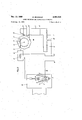
- Fig. 2 is a schematic view and wiring diagram of the mechanism for controlling movement of the sound recording and reproducing head and of the sound track bearing recording of the device. 7
- FIG. 1 there is shown a portion of a sound recording and reproducing device of a presently preferred embodiment of the invention.
- a sound recording and reproducing device of a presently preferred embodiment of the invention.
- Such device incorporates a horizontal record-supporting table 26 having an arcuate slot therein, indicated by dotted lines.
- An elongated sound track receiving and bearing record 27, incorporating at least a layer of magnetic material lies upon the table 26, as shown, and is driven by means to be described with a step-by-step movement past the slot in the table and longitudinally of the record, each movement of the record occurring immediately after the head 24 has reached one of the termini 28, 29 of the slot.
- the device when it is recording sound, it creates a Zigzag sound track upon the record, such sound track being composed of a series of parallel arcuate runs lying generally transverse to the length of the record, successive runs of the sound track being connected by short runs along the sides of the record and lying parallel thereto.
- the shaft 5 bearing the head 24 is oscillated by a mechanism such as that shown and described in the related patent application Serial No. 529,608, filed August 22, 1955, which corresponds to French patent application Serial No. 682,189, filed December 21, 1954.
- the mechanism for oscillating shaft 5 there shown comprises a piston, specifically a solenoid plunger, which is alternately moved in reverse directions by a driving mechanism.
- a crank and lever system connects the piston or solenoid plunger to the shaft 5, whereby to oscillate the shaft upon reciprocation of the piston.
- the piston or solenoid plunger is reciprocated by two alternately energized solenoid cells 1 and 2.
- the record 27 is provided with a series of edge notches 32 along each longitudinal edge thereof, such edge notches meshing with the respective one of the two worm gears 21 and 25 which are mounted on opposite sides of the table 26 parallel to the length thereof and with their axes lying generally in the plane of the record ly ing on the table 26.
- the worm gears 21 and 25 are of opposite hand, so as to maintain the record stably on the table 26 during record-driving rotation of the worm gears.
- the worm gears are, connected together, by means not shown, and are driven at the same speed by means comprising a ratchet wheel 11 which is intermittently rotated by a solenoid 8 having a solenoid coil 8', and a plunger 9 which is biased to the right (Fig. 2) by a spring means not shown.
- ratchet Wheel 11 and gear 31 are mounted to rotate together on shaft 10.
- Gear 31 meshes with the smaller gear 30 on shaft 20.
- the device of the invention incorporates controlling mechanism whereby record-advancing movement of the worm gears takes place only after the sound recording and reproducing head has reached each terminus of its travel.
- the control device further is so constructed and arranged that when the record 27 bearing a recorded sound track thereon is mounted on the machine at an initial reproducingposition longitudinally thereof with respect to the path of travel of the head, the initial soundreproducing traverse of the head will automatically be in the correct position to reproduce the sound on the record; in other words, the head will automatically travel in the same direction in which the sound track was recorded.
- Such control means comprises a first switch having a V-shaped contactor 7 fixedly mounted on the oscillating shaft 5. As shown, contactor 7 is connected to the groundedlead 16 from a current source, not shown.
- the first switch has a central fixed contact block 6 bearing opposite contacts 61 and 62 which cooperate, respectively, with the contact points 71 and 72 mounted adjacent the outer end of each arm of the movable contactor 7.
- the switch is so arranged that, when the head 24 is in one terminal position, the energizing circuit for the solenoid 8' is completed through the contacts 61 and 71 of the switch, and then when the head 24 is in its other terminal position, the energizing circuit for the coil 8' of the solenoid is completed through contacts 62 and 72.
- a movable grounded contactor 12 of a second switch Mounted on shaft 10 to rotate with ratchet wheel 11 is a movable grounded contactor 12 of a second switch.
- Contactor 12 has a series of radial projections 13, 13, on its outer rim, there being half as many of such projections as there are operative teeth on the ratchet wheel 11.
- a fixed contactor blade 14 is mounted angularly with respect to contactor 12 so that a circuit is completed between a projection 13 of contactor 12 and blade 14 each time the ratchet wheel 11 has completed one of a first alternate series of record-advancing partial rotations.
- the projections 13 on contactor 12 and switch blade 14 function alternately to energize and de-energize the coil 1 of the first solenoid through the circuit 3, 18 and 17.
- the first solenoid impels the sound head 24 in one direction.
- the solenoid 1 and the sound head 24 are driven in said first direction only at the end of each of the first alternate sets of record-advancing movements.
- a second fixed switch blade is positioned outwardly of the contactor 12 at a position displaced from the switch blade 14 at an angle equalling the angle between successive operative ratchet teeth on the ratchet wheel 11.
- Switch blade 15 is interposed in the energizing circuit 4, 18, and 17, for the second solenoid 2 for energizing the head-driving solenoid plunger in the second reverse direction.
- Solenoid coil 2- is, therefore, energized when the ratchet wheel 11 and the contactor 12 are moved counterclockwise from the position of Fig. 2 through an angle equalling the angle between operative ratchet teeth on ratchet wheel 11. In such position the projection 13' on contactor 12 contacts switch blade 15, and the contact between the switch blade 14 and contactor 12 is broken. Solenoid coil 2, therefore, moves the sound head in the second, reverse direction only after each of the second alternate series of record movements.
- solenoid coil 1 functions to advance the record only when the head 24 has reached a given one of its termini, and that solenoid coil 2 will be energized only when head 24 has reached the other one of its termini.
- the machine establishes a fixed correlation, not only between the timing of the step-by-step record advance, but also between the direction in which the sound track on the recordwas recorded and the direction in which the head moves to reproduce the sound track.
Landscapes
- Recording Or Reproducing By Magnetic Means (AREA)
- Moving Of Heads (AREA)
- Adjustment Of The Magnetic Head Position Track Following On Tapes (AREA)
Applications Claiming Priority (1)
| Application Number | Priority Date | Filing Date | Title |
|---|---|---|---|
| FR1120142T | 1955-01-17 |
Publications (1)
| Publication Number | Publication Date |
|---|---|
| US2964324A true US2964324A (en) | 1960-12-13 |
Family
ID=9631315
Family Applications (1)
| Application Number | Title | Priority Date | Filing Date |
|---|---|---|---|
| US529609A Expired - Lifetime US2964324A (en) | 1955-01-17 | 1955-08-22 | Sound recording and reproducing apparatus |
Country Status (8)
| Country | Link |
|---|---|
| US (1) | US2964324A (de) |
| AT (1) | AT195138B (de) |
| CA (1) | CA629140A (de) |
| CH (1) | CH333984A (de) |
| DE (1) | DE1063398B (de) |
| ES (1) | ES233450A3 (de) |
| FR (1) | FR1120142A (de) |
| GB (1) | GB792435A (de) |
Cited By (8)
| Publication number | Priority date | Publication date | Assignee | Title |
|---|---|---|---|---|
| US3124360A (en) * | 1964-03-10 | Dictating machine drive mechanism | ||
| US3129295A (en) * | 1958-12-22 | 1964-04-14 | Cie Crouzet | Automatic telephone call device |
| US3176083A (en) * | 1960-03-07 | 1965-03-30 | Hauser Fred | Recording and reproducing machine |
| US3255307A (en) * | 1961-09-08 | 1966-06-07 | Telefunken Patent | Magnetic recorder-reproducer having grooved tape |
| US3281803A (en) * | 1955-11-16 | 1966-10-25 | Scm Corp | Magnetic tape transducer apparatus |
| US3320371A (en) * | 1963-01-08 | 1967-05-16 | Bach Auricon Inc | Video tape recording apparatus utilizing transversely scanning erase and record heads |
| US3401945A (en) * | 1965-06-29 | 1968-09-17 | Electroacustic Gmbh | Sound-reproducing apparatus |
| US3583709A (en) * | 1969-01-14 | 1971-06-08 | Ibm | Scanning head direction memory device for recording and reproducing apparatus |
Families Citing this family (1)
| Publication number | Priority date | Publication date | Assignee | Title |
|---|---|---|---|---|
| DE1185838B (de) | 1961-07-28 | 1965-01-21 | Usines Gustave Staar S A | Antriebsvorrichtung fuer den bandfoermigen Aufzeichnungstraeger von Tonaufzeichnungs- und Wiedergabegeraeten mit quer zur Vorschubrichtung des Aufzeichnungstraegers erfolgender Aufzeichnung und Wiedergabe in Zeilenschrift |
Citations (7)
| Publication number | Priority date | Publication date | Assignee | Title |
|---|---|---|---|---|
| US462687A (en) * | 1891-11-10 | Phonograph | ||
| US2124673A (en) * | 1935-03-22 | 1938-07-26 | Puma John | Sound reproducing mechanism |
| US2127331A (en) * | 1936-01-09 | 1938-08-16 | Fulton Otho | Apparatus for use in facsimile transmitting systems |
| US2245286A (en) * | 1936-06-26 | 1941-06-10 | Marzocchi Luigi | Electromagnetic sound recording |
| FR877126A (fr) * | 1958-03-15 | 1942-11-27 | Licentia Gmbh | Appareil à dicter, d'après le procédé magnétique sonore |
| US2546829A (en) * | 1948-12-18 | 1951-03-27 | Bell Telephone Labor Inc | Magnetic recorder and reproducer |
| FR1041699A (fr) * | 1951-04-05 | 1953-10-26 | Procédé et appareil pour l'enregistrement et la reproduction des sons sur papier magnétique |
-
0
- CA CA629140A patent/CA629140A/en not_active Expired
-
1955
- 1955-01-17 FR FR1120142D patent/FR1120142A/fr not_active Expired
- 1955-08-22 US US529609A patent/US2964324A/en not_active Expired - Lifetime
-
1956
- 1956-01-11 AT AT195138D patent/AT195138B/de active
- 1956-01-11 GB GB984/56A patent/GB792435A/en not_active Expired
- 1956-01-11 CH CH333984D patent/CH333984A/fr unknown
- 1956-01-17 DE DEA24128A patent/DE1063398B/de active Pending
-
1957
- 1957-02-06 ES ES233450A patent/ES233450A3/es not_active Expired
Patent Citations (7)
| Publication number | Priority date | Publication date | Assignee | Title |
|---|---|---|---|---|
| US462687A (en) * | 1891-11-10 | Phonograph | ||
| US2124673A (en) * | 1935-03-22 | 1938-07-26 | Puma John | Sound reproducing mechanism |
| US2127331A (en) * | 1936-01-09 | 1938-08-16 | Fulton Otho | Apparatus for use in facsimile transmitting systems |
| US2245286A (en) * | 1936-06-26 | 1941-06-10 | Marzocchi Luigi | Electromagnetic sound recording |
| US2546829A (en) * | 1948-12-18 | 1951-03-27 | Bell Telephone Labor Inc | Magnetic recorder and reproducer |
| FR1041699A (fr) * | 1951-04-05 | 1953-10-26 | Procédé et appareil pour l'enregistrement et la reproduction des sons sur papier magnétique | |
| FR877126A (fr) * | 1958-03-15 | 1942-11-27 | Licentia Gmbh | Appareil à dicter, d'après le procédé magnétique sonore |
Cited By (8)
| Publication number | Priority date | Publication date | Assignee | Title |
|---|---|---|---|---|
| US3124360A (en) * | 1964-03-10 | Dictating machine drive mechanism | ||
| US3281803A (en) * | 1955-11-16 | 1966-10-25 | Scm Corp | Magnetic tape transducer apparatus |
| US3129295A (en) * | 1958-12-22 | 1964-04-14 | Cie Crouzet | Automatic telephone call device |
| US3176083A (en) * | 1960-03-07 | 1965-03-30 | Hauser Fred | Recording and reproducing machine |
| US3255307A (en) * | 1961-09-08 | 1966-06-07 | Telefunken Patent | Magnetic recorder-reproducer having grooved tape |
| US3320371A (en) * | 1963-01-08 | 1967-05-16 | Bach Auricon Inc | Video tape recording apparatus utilizing transversely scanning erase and record heads |
| US3401945A (en) * | 1965-06-29 | 1968-09-17 | Electroacustic Gmbh | Sound-reproducing apparatus |
| US3583709A (en) * | 1969-01-14 | 1971-06-08 | Ibm | Scanning head direction memory device for recording and reproducing apparatus |
Also Published As
| Publication number | Publication date |
|---|---|
| AT195138B (de) | 1958-01-25 |
| GB792435A (en) | 1958-03-26 |
| FR1120142A (fr) | 1956-07-02 |
| CH333984A (fr) | 1958-11-15 |
| DE1063398B (de) | 1959-08-13 |
| CA629140A (en) | 1961-10-17 |
| ES233450A3 (es) | 1957-05-16 |
Similar Documents
| Publication | Publication Date | Title |
|---|---|---|
| US2964324A (en) | Sound recording and reproducing apparatus | |
| US2419476A (en) | Winding control means for magnetic recording and reproducing apparatus | |
| US2694110A (en) | Equipment for use with magnetic tape records | |
| US2043789A (en) | Multiple record phonograph | |
| US2304913A (en) | Winding and reeling means for sound recording and reproducing apparatus | |
| US3870320A (en) | Pickup arm control for video disc player | |
| US2066041A (en) | Sound reproducing apparatus | |
| US2481398A (en) | Selector system for magnetic wire reproducers | |
| US3289962A (en) | Apparatus for and method of automatically changing tape cartridges | |
| US3512786A (en) | Tape player utilizing plurality of endless magnetic tape cartridges | |
| US897765A (en) | Multiple telegraphone system. | |
| US2910669A (en) | System for magnetic storage of data | |
| US3443037A (en) | Multitrack tape recorder with mechanical track-change system | |
| US3124360A (en) | Dictating machine drive mechanism | |
| US2873926A (en) | Magnetic tape recording equipment | |
| US3599986A (en) | Tape player utilizing plurality of endless magnetic tape cartridges | |
| US2869876A (en) | Sound recording and reproducing apparatus | |
| US2371116A (en) | Phonograph | |
| GB1152801A (en) | Improvements in or relating to Electric Signal Transducer Apparatus | |
| US2651461A (en) | Record sensing and data storage device | |
| US3254245A (en) | Stepping motor | |
| US2883476A (en) | Indexing means for drum-feed screw type translating device | |
| US3487374A (en) | Magnetic-film input-output element | |
| US3279708A (en) | Electrical solenoid winding machines | |
| US1859435A (en) | Sound-on-film phonograph |