US2957421A - Fuel supply pump for prime movers - Google Patents
Fuel supply pump for prime movers Download PDFInfo
- Publication number
- US2957421A US2957421A US416750A US41675054A US2957421A US 2957421 A US2957421 A US 2957421A US 416750 A US416750 A US 416750A US 41675054 A US41675054 A US 41675054A US 2957421 A US2957421 A US 2957421A
- Authority
- US
- United States
- Prior art keywords
- pump
- plate
- wobble plate
- fuel
- force
- Prior art date
- Legal status (The legal status is an assumption and is not a legal conclusion. Google has not performed a legal analysis and makes no representation as to the accuracy of the status listed.)
- Expired - Lifetime
Links
Images


Classifications
-
- F—MECHANICAL ENGINEERING; LIGHTING; HEATING; WEAPONS; BLASTING
- F04—POSITIVE - DISPLACEMENT MACHINES FOR LIQUIDS; PUMPS FOR LIQUIDS OR ELASTIC FLUIDS
- F04B—POSITIVE-DISPLACEMENT MACHINES FOR LIQUIDS; PUMPS
- F04B1/00—Multi-cylinder machines or pumps characterised by number or arrangement of cylinders
- F04B1/12—Multi-cylinder machines or pumps characterised by number or arrangement of cylinders having cylinder axes coaxial with, or parallel or inclined to, main shaft axis
- F04B1/26—Control
- F04B1/28—Control of machines or pumps with stationary cylinders
- F04B1/29—Control of machines or pumps with stationary cylinders by varying the relative positions of a swash plate and a cylinder block
- F04B1/295—Control of machines or pumps with stationary cylinders by varying the relative positions of a swash plate and a cylinder block by changing the inclination of the swash plate
Definitions
- This invention relates to fuel pumps of the variable displacement, reciprocating plunger swash plate type for pressurizing fuel to prime movers, especially gas turbine engines for aircraft, and adapted to respond automatically to a change in pressure requirements.
- Certain types of engines notably turbojet engines for aircraft, may require extremely high delivery pressures at the burner discharge nozzles to obtain good fuel atomization and efiicient combustion, and the nozzle pressure requirements may vary over a wide range between operation at sea level and high altitudes.
- the reciprocating plunger, swash plate type of pump is well adapted to supply fuel at high pressures, but automatic regulation or variation of pump delivery in relation to engine fuel requirements poses quite a problem, and an object of the present invention is to provide in a pump of the type specified self-contained, reliable, regulator mechanism which acts to vary the angle of the swash plate as a function of pump discharge pressure and engine speed.
- Another object is to provide in a pump of the type specified regulator mechanism which may be readily adapted to deliver fuel at pressures conforming todifferent engine requirements.
- Another object is to provide in a pump of the type.
- specified regulator mechanism operative to control the pumping stroke in such a manner that sufficient discharge pressure is maintained for the required fuel delivery under all operating conditions and said pressure is also automatically maintained within safe limits so as to maximize the operating life of the pump.
- a further and more specific object is to provide regulator mechanism for a swash or wobble plate type of fuel pump embodying means for interposing a resilient force on the plate tending to push the plate to maximum stroke position against the resistance of plunger return springs, which mechanism may be arranged so that such force will remain substantially constant throughout the different pitch positions of said plate, or will vary according to any desired predetermined schedule.
- Another object of this invention is to provide regulator mechanism for a swash or wobble plate type of fuel pump embodying means for producing a resultant of mechanical moments about the pivot or trunnion of the swash plate at any given pump speed which varies in such a way that pump discharge pressure follows, or is a direct function of pump flow at each given pump speed.
- a further object is to provide regulator mechanism for a pump of the type specified embodying pump speed sensing means arranged to vary the effective moment force about the trunnion of the swash plate in a predetermined manner, as the swash plate moves from a zero to a maximum stroke position at any given pump speed,
- Another object is to provide regulator mechanism for a pump of the type specified embodying pump speed sensing means arranged to vary the effective moment force about the trunnion of the swash plate in a predetermined manner at a given position of the swash plate during an increase in pump speed.
- Another object is to provide regulator mechanism for a pump of the type specified embodying means for controlling or offsetting the effect of pump plunger inertia irrespective of variations in pump speed or swash plate position.
- Another and more specific object is to provide regulator mechanism for a pump of the type specified embodying centrifugal weight speed sensing means geometrically located with respect to the pivotal axis of the swash plate in such a manner that its effective distance from saidaxis increases at a rate greater than its radial moment decreases as the swash plate moves from zero to maximum stroke position for increasing discharge pressure with an increase in flow.
- a further object is to provide regulator mechanism for a swash plate type of fuel pump embodying pump speed sensing variable moment of the pumping position of the swash plate and/or pump speed, and means for interposing a resilient force on the plate tending. to actuate said plate to maximum stroke position, which force varies in a desired preselected manner.
- FIG. 1 pump in accordance with the invention
- FIG. 2 is a central longitudinal section through they pump of Figure 1, only such parts being shown as are necessary to an understanding of the invention;
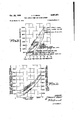
- Figures 3 and 4 are curve charts illustrating the operation of the pump as shown in Figure 2;
- Figure 5 is a view in perspective of an assembly which constitutes a modification of the pump control mechanism which is shown in Figure 2;
- Figure 6 is another perspective of the assembly of Figmeans arranged to impose a preselectedforce on the swash plate as a function is unbalanced in a direction. tending to assist the hydraulic reaction on the plungers.
- fuel back pressure may have any preselectedv other objects and advantages will' is a schematic view of a fuel supply system: for a gas turbine engine utilizing a variable displacement me 5 as viewed from the bottom or opposite end of the latter figure, with the wobble plate of the pump control mechanism partly broken away;
- Figures 7 and 8 are curve chartsillustrating one of the characteristics obtainable with a. pump when equipped with the unit of Figures 5 and 6;
- FIG 9 is a fragmentary view of pump control mechanism which constitutes another modification of the mechanism shown in Figure 2;
- Figures 10 and 11. are curve charts illustrating the operation of the control of Figure 9.
- a fuel manifold for a gas turbine engine is indicated at 10; it has connected thereto a plurality of fuel lines 11 which conduct fuel under pressure to. burner nozzles 12, the latter discharging fuel into the combustion chambers of the burner system, not shown.
- the fuel supply is under manual regulation by means of a fuel control unit 13, which may be of any type suitable for the function which it is designed to perform.
- a control unit of thetype disclosed in my Patent No. 2,689,606, filed December 13, 1946, may be used.
- the rate of fuel feed is determined by the pilot through a control lever 14 which is connected to an all-speed governor throttle valve, not shown, adapted to vary the eifective area of one or more feed restrictions, the fuel head across the said restrictions being automatically varied as a function of engine speed and changes in entering air density to, among other things, maintain the rate of fuel feed Within predetermined temperature limits andcompensate for changes in altitude.
- the fuel is pressurized to the unit by means of an engine driven variable displacement pump, generally indicated at 15, which receives its fuel from a suitable source of supply such as a fuel tank, not shown, by way of conduit16, the fuel being discharged under pressure to the control unit by way of conduit 17.
- the member indicated at 18 is a pressure valve which determines the maximum delivery pressure to the nozzles 12, and when such pressure is exceeded, the meteredfuel is by-passed or returned to the supply conduit 16 by way of a conduit 19.
- the unit indicated at 20 is a barometric element designed to automatically vary the rate of fuel feed as a function of changes in entering air density; it prevents the fuel-air ratio from becoming too rich as altitude is gained and which would otherwise result in excessively high burner temperatures and overspeeding of the engine when operating at high altitudes.
- the pump comprises a series of plungers 21 which are symmetrically disposed inannular formation and are mounted to reciprocate in plunger bushings or cylinders 22.
- the plungers are retracted by means of springs 23, which at their outer ends engage retainers 24 connected to the adjacent ends of the plungers.
- Each plunger has mounted'on its outer end a conventional bearing shoe or slipper 25 which is adapted to engage the bearing surface of a cam plate 26.
- the plungers are moved inwardly or towards discharge position by means of a wobble or swash plate 27, shown position, which acts on the plate 26
- the pump drive shaft is indicated at 29; it is located concentrically of the plungers 21 and has its opposite ends mounted in bearings On the
- the wobble plate 27 is provided with mounting or hanger brackets 27', which are secured'on the opposite ends of a trunnion 33, the latter being mounted on the drive shaft 29 in ofiset or eccentric relation to the longitudinal axis thereof.
- a centrifugal Weight 34 is also carried by the shaft 29; it is secured on a pin or trunnion 35 which is provided with a hub portion formed with a gear 36 in constant mesh with a coacting gear segment 37 formed on the adjacent end of a lever 38, the latter having a hub portion 39 secured on the adjacent end of the trunnion 33.
- a check valve 43 which is normally urged to its seat by a spring 44, said valve preventing the fuel from being pressurized to the intake side of the pump.
- the ends of the cylinders 22 are each provided with a check valve 45, which is unseated against a spring 46 when the plungers are moved inwardly due to the action of the wobble plate 27.
- a check valve 45 When these valves are unseated on the delivery stroke of the plungers 21, fuel is discharged to the conduit 17 by way of passages 47 which feed into a common passage 48.
- a spring 50 is disposed to hear at one end against an arm 49 projecting outwardly from the drive shaft 29 and at its opposite end against the wobble plate 27.
- This spring tends to tilt the wobble plate toward maximum stroke position; it functions to tilt the plate in a stroke-increasing direction when the reaction pressure drops as by an opening movement of the throttle of the fuel control unit 13; it throws the said plate to a full stroke angle when the pump or engine is idle, so that when the latter again starts up, there will be no lag in pump delivery; and it also maintains a minimum discharge pressure at low pump or engine speeds which minimum pressure may be sufiicient to compensate for the drop across the control 13.
- the dotted nozzle requirement curve represents the schedule of pres sure versus flow required under all engine operating conditions just beyond the control 13 on the way to the pressure valve 18.
- Three of the pump speed points on said requirement curve illustrate the' required pressure versus matter of choice and convenience in flow relation for a condition of maximum fuel consumption during acceleration at sea level. Less fuel would be used at these engine speeds during operation, at cruising power or at altitude or during engine deceleration, as illustrated by two of the 1750 rpm.
- the straight pump pressure lines represent fuel delivery pressures at three different pump speeds as the wobble plate angle, and hence the plunger stroke, goes from zero to a maximum.
- the right-hand terminus of each of these lines represents the quantity of fuel delivered at maximum pump stroke and consequently the maximum fuel available from the pump at the speed indicated.
- the pressure at each flow point must, of course, lie well above the nozzle pressure requirement at the same flow, to absorb across the control unit 13. The difference between the maximum pressure that the pump is capable of at any given pump speed and flow and the nozzle pressure requirement at the said flow should equal or exceed the amount of pressure drop the fuel control requires to meet said flow requirements thru the engine nozzles at said pump speed.
- Figure 4 plots pump discharge pressure against pump speed at maximum plate angle to indicate how the pressure increases as pump or engine speed increases; and also in relation to discharge nozzle requirements under acceleration at maximum air density.
- FIGs 5 and 6 show a wobble plate spring assembly which may be substituted for the spring 50 of Figure 2 to obtain the above noted and other advantages.
- parts which correspond to similar parts in Fig ure 2 are given similar reference numerals.
- the wobble plate is indicated at 27, the pump drive shaft at 29 and the wobble plate mounting trunnion or shaft at 33.
- the single spring 50 of Figure 2 there are preferably two springs 50', this'being primarily a design.
- the wobble plate 27 has its hanger brackets secured to and rotatable with the trunnion or shaft 33.
- the hubs 51 (one of which is visible in Figure 6) of a pair of arms 52 and 52 carrying segmental gears 53 and 54, which are in constant mesh with pinions 55 and 56 (shown as of segmental form) having their hubs pinned to a shaft 57.
- pinions 55 and 56 shown as of segmental form
- the springs 50' are mounted on guide pins 61 and 62, which have their free ends slidingly projecting through holes 63 and 64 formed in the shaft and their opposite ends pivotally anchored on a bearing pin 65 projecting through a bearing lug 66 formed on the pump drive shaft 29.
- the shaft 57 is rotatabiy mounted in a bearing block 67 shown as clamped on the said drive shaft 29, but which in practice could obviously be formed integral with said shaft.
- any tilting movement imparted to the wobble plate 27 produces rotation of shaft 33, and this acts through segmental gears 53 and 54 to produce a counter-rotation of shaft 57 and a rocking movement of lever arms 58 and 59. If the wobble plate 27 is tilted counterclockwise, or toward zero stroke position, as viewed in Figure 5, it will cause clockwise movement of said lever arms, and vice versa.
- lever arms 58 and 59 should lie in a plane substantially at right angles to the guide pins 61 (the longitudinal thrust axis of springs 50) when maximum stroke position.
- the springs 50 are in maximum extension while the effective moment arm of said springs about the shaft 33 is at a maximum.
- the resistance to movement of the wobbleplate in a counterclockwise or stroke decreasing direction remains substantially constant throughout the range of tilting movement of said plate, and conversely, the spring moment tending to move said plate in a clockwise or stroke increasing direction remains substantially constant while at the same time it is sufficient to move the wobble plate to or toward a maximum stroke position when back pressure on the plungers is reduced.
- the levers 58 and 59 may be arranged such that the effective thrust moment of springs 50 about shaft 33 may be made to either increase or decrease, by any selected amount, as the wobble plate moves from its maximum to its zero stroke position, whereby a great variety of fuel discharge pressure values may be obtained at any given engine or pump speed and/ or throttle position by variation in design according to the applicants invention.
- a speed sensing weight may be used in Figures 5 and 6 to obtain predetermined engine speed vs. discharge pressure characteristics such as described in connection with Figures 1 to 4, inclusive.
- a centrifugal Weight such as that indicated at 34 in Figure 5
- the mechanical moment of the plungers on the wobble plate tending to increase the pitch of the latter will be assisted by the centrifugal weight as the speed of rotation increases, and as a consequence, a given change in back is in a direction tending to the wobble plate is at full tilt or or reaction pressure at high speeds will proportionally be less effective to flatten the plate than at lower speeds.
- Figures 7 and 8 an attempt has been made to illustrate the operating characteristics of a pump when equipped with the assembly of Figures and 6 having the weight 34 arranged as shown.
- Figure 7 plots the resultant of the mechanical moment about the center line of the Wobble plate trunnion '33 (which tends to increase the pitch of said plate) against plunger stroke at pump speeds of 3500, 1750 and 875 r.p.m.
- Figure 8 plots this same factor against pump speed at different plunger strokes.
- the right-hand ordinate in Figures 7 and 8 indicates the hydraulic back pressure tending to decrease the pitch of the wobble plate.
- the pumps have a characteristic as illustrated in Figures 3 and 4 or 7 and 8, and if both are running at some intermediate speed, for example 1700 r.p.m., and both are momentarily at an intermediate stroke, if some condition should cause a change in the pressure vs. fiow characteristics of one pump, or would throw it out of balance with respect to the other, its wobble plate would tend to flatten and its plunger stroke decrease, While at the same time, the other pump would go to full stroke to take care of the fuel supply. In such case, the fuel pressure must increase with decreasing stroke so that under common pressure both pumps will share the load. However, to improve the life of the pump, the pressure is still controlled so as to reduce with speed, and altitude recirculation is avoided.
- centrifugal compensation be provided which will vary with r.p.m. but be independent of wobble plate pitch or pump stroke; this requires centrifugal force generating means positionably variable to overcome the stroke increasing tendency of pump plunger inertia.
- the desired increase in pressure with speed must be obtained by additional centrifugal force generating means of substantially constant moment with changes in wobble plate pitch.
- Figures and '11 show a delivery characteristic desirable for parallel pumps which may be obtained by modifying the centrifugal speed weight arrangement of Figure 2, as shown in Figure 9 wherein the swash plate is shown in zero stroke position, or by a predetermined balancing of the lever arms 58 and 59 of Figures 5 and 6.
- Figure 9 is drawn along the lines of Figure 2, like parts being given corresponding reference numerals.
- the weight 34 there is a weight 68 which functions primarily to oppose the effect of plunger inertia on the wobble plate (which tends to increase the pitch of the wobble plate), whereas the weight 34 tends to increase the resistance of the wobble plate to the effect of discharge pressure at high speeds; it
- the radius of Weight 68 decreases slightly and its moment vector increases substantially thereby resulting in an effective moment force which tends to flatten the plate and which may exactly counteract or balance pump plunger inertia effect or control it in a predetermined manner.
- a fluid pump having a tiltable wobble plate carried by a rotatable pump drive shaft and adapted to impart pumping strokes to a plurality of pistons or plungers, means pivotally mounting said wobble plate on said shaft in offset or eccentric relation to a center common to the group of plungers and in a direction to assist the pumping reaction effect on the plungers, and pump regulator means including a centrifugal weight mounted on said shaft and operatively connected to said plate exerting a force which varies with variations in pump speed and which tends to tilt the wobble plate progressively towards maximum stroke position with progressive increases of pump speed during the full speed range of operation of the pump.
- a fluid pump having a tiltable wobble plate carried by a rotatable pump drive shaft and adapted to impart pumping strokes to a plurality of pistons or plungers, means pivotally mounting said wobble plate on said shaft in offset or eccentric relation to a center common to the group of plungers, pump regulator means including a centrifugal weight mounted on said shaft and operatively connected to said wobble plate for imposing a centrifugally generated force on the wobble plate during operation .9 of the pump, said force varying in'rela'tion' to the tilt of the wobble plate and in relation to pump speed and applied in a direction tending to tilt said wobble plate in a stroke increasing direction, and resilient means exerting a mechanical force on the wobble plate in a stroke increasing direction.
- a fluid pump having a tiltable wobble plate carried by a rotatable pump drive shaft and adapted to impart pumping strokes to a series of annularly disposed pistons or plungers, means pivotally mounting said wobble plate on said shaft, a centrifugal weight also rnounted on said shaft adjacent said wobble plate and operatively connected thereto in a manner such as to exert a force on the latter which tends to tilt the plate towards maximum stroke position and which varies in relation to the speed of the pump, and a spring operatively connected to said wobble plate which tends to tilt said plate in a stroke increasing direction, said operative connection including variable leverage means for transmitting the force of said spring to said plate.
- a fluid pump having a tiltable wobble plate carried by a rotatable pump drive shaft and adapted to impart pumping strokes to a plurality of annularly disposed pistons or plungers, means pivotally mounting said wobble plate on said shaft in ofiset or eccentric relation to a center common to the group of plungers and in a direction to assist the pumping reaction effect on the plungers, a speed sensing weight rotatable with said shaft mounted adjacent said wobble plate and operatively connected thereto, and a spring operatively connected to said wobble plate for urging said plate towards maximum stroke position, said latter operative connection including means connecting said spring between the shaft and wobble plate in a manner such that the effective spring thrust on said plate will be maintained substantially constant irrespective of variations in the tilt of the plate.
- a fluid pump having a tiltable wobble plate carried by a rotatable pump drive shaft and adapted to impart pumping strokes to a series of annularly disposed pistons or plungers, means pivotally mounting said wobble plate on said shaft, a speed sensing weight rotatable with said shaft mounted adjacent said wobble plate and operatively connected thereto for imposing a force on said plate which tends to vary the pitch thereof as a function of pump speed, other means operatively connected to said wobble plate for modifying the efiect of pump plunger inertia on said plate, and resilient means operatively connected to said plate for exerting a tilting force there- 6.
- a fluid pump having a tiltable wobble plate carried by a rotatable pump drive shaft and adapted to impart pumping strokes to a series of annularly disposed pistons or plungers, means pivotally mounting said wobble plate on said shaft, means including a centrifugal weight mounted on said shaft for generating a centrifugal force which tends to tilt the wobble plate towards maximum stroke position during operation of the pump, spring means operably connected to said wobble plate also tending to tilt said plate towards maximum stroke position, and means for generating an additional centrifugal force for counteracting the effect of plunger inertia which tends to increase the pitch of the wobble plate with an increase in pump speed.
- a fluid pump having a tiltable wobble plate carried by a rotatable drive shaft and adapted to impart pumping strokes to a series of annularly disposed reciprocable pistons or plungers, a pair of centrifugal weights mounted on said shaft adjacent said wobble plate, and means operatively connecting each of said weights to said wobble plate, one of said weights being arranged to exert a force on said plate which tends to increase the tilt thereof with an increase in engine speed, and the other of said weights being arranged to exert a force on said plate which modifies he efiect of pump plunger inertia on said plate.
- a fluid pump having a tiltable wobble plate" carried by a rotatable pump drive shaft and adapted to impart pumping strokes to a plurality of pistons or plungers, means pivotally mounting said wobble plate on said shaft, a centrifugal weight rotatable with said shaft mounted adjacent said wobble plate and operatively connected thereto so as to exert a variable force thereon, and, yielding means also operatively connected to the wobble plate tending to tilt said plate in a stroke increasing direction, said latter operative connection including leverage means for transmitting the force of said yielding means to said plate and to maintain said last named force substantially constant.
- a fluid pump having a tiltable wobble plate carried by a rotatable pump drive shaft and adapted to impart pumping strokes to a plurality of pistons or plungers, pump regulator means comprising a centrifugal weight rotatable with the drive shaft mounted adjacent said wobble plate and operably connected thereto, yielding means adapted to move said wobble plate towards maximum'stroke position, and means operably connecting said yielding means between the shaft and wobble plate in such a manner that the moment force of the yielding means on the said plate will increasingly oppose movement of said plate towards the minimum pump stroke position thereof.
- a tiltably pivoted swash plate regulator means for controlling the pumping position of the swash plate comprising resilient means secured against axial movement at one end thereof and operatively connected to the swash plate at the other or axially movable end thereof for imposing a substantially constant effective torque on said swash plate at all pumping positions thereof, said operative connection including means effective to nullify the effect of variations in force output of said resilient means as said swash plate is actuated from one pumping position to another.
- a tiltably pivoted swash plate, shaft means for carrying said swash plate, and regulator means for controlling the pumping position of the swash plate comprising a shaft carried by said shaft means on which said plate is pivoted, resilient means secured against axial movement at one end thereof and operatively connected to said pivot shaft and swash plate at the other or axially movable end thereof, said operative connection including a pivot member also carried by said shaft means, leverage means pivoted on said member and abutting and movable with the movable end of said resilient means, and mechanism connecting said member to said pivot shaft for transmitting the torque output of said resilient means to said swash plate.
- a fluid pump having a tiltable wobble plate carried by a rotatable pump drive shaft and adapted to impart pumping strokes to a plurality of annularly disposed pistons or plungers, means pivotally mounting said wobble plate on said shaft in offset or eccentric relation to a center common to the group of plungers and in a direction to assist the pumping reaction effect on the plungers, a speed sensing means rotatable with said shaft and operatively connected to said wobble plate so as to exert a force on the latter tending to tilt the plate towards maximum stroke position, said force varying as a function of pump speed, resilient means operatively connected to said wobble plate also tending to tilt the wobble plate towards maximum stroke position, said latter operative connection including variable leverage means for transmitting the force output of said springs to said plate, and means imposing a centrifugally generated force on the wobble plate during operation of the pump, said latter means being arranged so that said force tends to counteract the effects of pump plunger inertia on said plate.
- a fluid pump having a tiltably pivoted swash plate supported by a shaft and adapted to impart strokes to a series of pistons or plungers, pump control means for producing a resultant mechanical moment about the pivot of the swash plate which varies in such a way that pump discharge pressure varies as a predetermined function of pump flow, said control means including a centrifugal weight mounted on said shaft and operatively connected to the swash plate and geometrically located with respect to the pivotal axis of said plate in such a manner that its elfective distance from said axis increases at a rate greater than its radial moment decreases as the swash plate moves from zero to maximum stroke position, and means operatively connected to the swash plate for controlling the effect of pump plunger inertia thereon in a predetermined manner.
- a fluid pump having a tiltably pivoted wobble plate supported by a shaft means and adapted to impart pumping strokes to a plurality of pistons or plungers, rotatably mounted pump speed sensing means adjacent said wobble plate and operatively connected thereto to impose a variable moment force on the wobble plate, which force varies as a function of pump speed and tends to tilt said wobble plate in a maximum stroke direction, and mechanism including resilient means and variable leverage means applying a force on the plate which tends to actuate said plate towards maximum stroke position,
Landscapes
- Engineering & Computer Science (AREA)
- Mechanical Engineering (AREA)
- General Engineering & Computer Science (AREA)
- Reciprocating Pumps (AREA)
Description
Oct. 25, 1960 Filed March 17, 1954 F. c. MOCK 2,957,421
FUEL SUPPLY PUMP FOR PRIME MOVERS 6 Sheets-Sheet 2 MAX. smoxe cutzva 2 -FUEL comm. PRESS m? u] ZIOO I g )35OORZFH-ACCH @ssa LEVEL I800 I n I I x200 I r g s Ki ll 3. soc H oz r.
D E00! imam cullvE y g 600 \150 -M- Aces sen maven.
- .-s nw sure sea LEVEL 815 R4. wanna an LEVEL ecu. @S.L. onvs EAW arm-e ALT- O 4' is a' so :2 l4
FUEL YLOW PER PUHP- LBS PER HOURlHOi g 3 a 800 goo m2 5 and KO 2H; Too 9 20- 0B U U 2 I v F E5OO pg 2mm a u-I x Q U 0 K42! )QC 200 v INVENTOR o \000 2000 8 FFAA/AC N064 PUMP REM. 5y 5 I F. b. MOCK FUEL SUPPLY PUMP FOR PRIME MOVERS Oct. 25,- 1960 6 Sheets-Sheet 3 Filed March 17, 1954 a m r m w R I E P R M NU U E y Q m m m L M Z w m P O D w I J w w w w w m w o M a m w P v w Yum -umsmnumu MQMZIUQO mist PUM P REM.
EE Sumo; a K mo 18.5 $5.53 2. m C uzEzE. nm 5503?. N 0 M62136 12am 5 M w w w 0 w. n m n K M m. W m w. M m w. w. W m 5 f a 5 R 7 0 AM 7 m "m I a W E mm 1 m wwwwww m 8 7 6 5 4 3 N .l 92 530; no 5t. $552 9. wzEzmF u 2923b .534 3 52. n.Ew.
Oct. '25, 1960 F. c. MOCK 2,957,421
. FUEL SUPPLY PUMP FOR PRIME MOVERS Filed March 17, I954 6 Sheets-Sheet 4 INVENTOR. FIPA/VA/KT/VUC'K ATTOAA/flf FUEL SUPPLY PUMP FOR PRIME MOVERS Filed March 17, 1954 6 Sheets-Sheet 5 INVENTOR.
a FRANK (War/r United States Patent 2,957,421 FUEL SUPPLY PUMP FOR PRINIE MOVERS Frank C. Mock, South Bend, Ind., assignor to The Bendix Corporation, a corporation of Delaware Filed Mar. 17, 1954, Ser. No. 416,750
14 Claims. (Cl. 103-38) covering a Fuel Supply Pump for Prime Movers, which application will now be permitted to lapse in view of its being superceded by the present application.
This invention relates to fuel pumps of the variable displacement, reciprocating plunger swash plate type for pressurizing fuel to prime movers, especially gas turbine engines for aircraft, and adapted to respond automatically to a change in pressure requirements. Certain types of engines, notably turbojet engines for aircraft, may require extremely high delivery pressures at the burner discharge nozzles to obtain good fuel atomization and efiicient combustion, and the nozzle pressure requirements may vary over a wide range between operation at sea level and high altitudes. The reciprocating plunger, swash plate type of pump is well adapted to supply fuel at high pressures, but automatic regulation or variation of pump delivery in relation to engine fuel requirements poses quite a problem, and an object of the present invention is to provide in a pump of the type specified self-contained, reliable, regulator mechanism which acts to vary the angle of the swash plate as a function of pump discharge pressure and engine speed.
Another object is to provide in a pump of the type specified regulator mechanism which may be readily adapted to deliver fuel at pressures conforming todifferent engine requirements.
Another object is to provide in a pump of the type.
specified regulator mechanism operative to control the pumping stroke in such a manner that sufficient discharge pressure is maintained for the required fuel delivery under all operating conditions and said pressure is also automatically maintained within safe limits so as to maximize the operating life of the pump.
A further and more specific object is to provide regulator mechanism for a swash or wobble plate type of fuel pump embodying means for interposing a resilient force on the plate tending to push the plate to maximum stroke position against the resistance of plunger return springs, which mechanism may be arranged so that such force will remain substantially constant throughout the different pitch positions of said plate, or will vary according to any desired predetermined schedule.
Another object of this invention is to provide regulator mechanism for a swash or wobble plate type of fuel pump embodying means for producing a resultant of mechanical moments about the pivot or trunnion of the swash plate at any given pump speed which varies in such a way that pump discharge pressure follows, or is a direct function of pump flow at each given pump speed.
A further object is to provide regulator mechanism for a pump of the type specified embodying pump speed sensing means arranged to vary the effective moment force about the trunnion of the swash plate in a predetermined manner, as the swash plate moves from a zero to a maximum stroke position at any given pump speed,
for establishing a predetermined schedule of pump discharge pressure versus flow at each given speed.
Another object is to provide regulator mechanism for a pump of the type specified embodying pump speed sensing means arranged to vary the effective moment force about the trunnion of the swash plate in a predetermined manner at a given position of the swash plate during an increase in pump speed.
Another object is to provide regulator mechanism for a pump of the type specified embodying means for controlling or offsetting the effect of pump plunger inertia irrespective of variations in pump speed or swash plate position.
Another and more specific object is to provide regulator mechanism for a pump of the type specified embodying centrifugal weight speed sensing means geometrically located with respect to the pivotal axis of the swash plate in such a manner that its effective distance from saidaxis increases at a rate greater than its radial moment decreases as the swash plate moves from zero to maximum stroke position for increasing discharge pressure with an increase in flow.
A further object is to provide regulator mechanism for a swash plate type of fuel pump embodying pump speed sensing variable moment of the pumping position of the swash plate and/or pump speed, and means for interposing a resilient force on the plate tending. to actuate said plate to maximum stroke position, which force varies in a desired preselected manner.
In carrying out the invention, I ofiiset the pivotal mounting of the wobble plate with respect to a center common to the annularly symmetrically-arranged pump plungers so that the plate of the fluid being pumped to move the wobble plate to creases the sensitivity of the plate to changes in plunger or more centrifugal Weights "plate to a maximum stroke position with a force which reaction pressure due to variations in from an external source, as by changes in throttle settings. These forces tending to move the swash plate to zero stroke position are opposed by the action of one tending to tilt the wobble varies with variations in and by a spring force constant rate or value plate angle and engine speed, which may have a substantially throughout the effective tilt of The resulting control will automatically vary the angle of the wobble plate, and hence delivery pressure, in response to changes in throttle setting, and may be readily adapted to different fuel flow requirements.
The foregoing and become apparent in view of the description which follows when taken in conjunction with the appended drawings in which:
Figure 1 pump in accordance with the invention;
Figure 2 is a central longitudinal section through they pump of Figure 1, only such parts being shown as are necessary to an understanding of the invention;
Figures 3 and 4 are curve charts illustrating the operation of the pump as shown in Figure 2;
Figure 5 is a view in perspective of an assembly which constitutes a modification of the pump control mechanism which is shown in Figure 2;
Figure 6 is another perspective of the assembly of Figmeans arranged to impose a preselectedforce on the swash plate as a function is unbalanced in a direction. tending to assist the hydraulic reaction on the plungers.
fuel back pressure may have any preselectedv other objects and advantages will' is a schematic view of a fuel supply system: for a gas turbine engine utilizing a variable displacement me 5 as viewed from the bottom or opposite end of the latter figure, with the wobble plate of the pump control mechanism partly broken away;
Figures 7 and 8 are curve chartsillustrating one of the characteristics obtainable with a. pump when equipped with the unit of Figures 5 and 6;
Figure 9 is a fragmentary view of pump control mechanism which constitutes another modification of the mechanism shown in Figure 2; and
Figures 10 and 11. are curve charts illustrating the operation of the control of Figure 9.
It will be understood from the following description that the. spring control mechanism shown-in Figures 5 and 6 of the drawings is intended to be substitutable for the spring control shown in Figures 2 and. 9, said latter spring control being illustrated in simple form so as to avoid unnecessary complexity in the drawings.
Referring to the drawings, and first to Figure 1, a fuel manifold for a gas turbine engine is indicated at 10; it has connected thereto a plurality of fuel lines 11 which conduct fuel under pressure to. burner nozzles 12, the latter discharging fuel into the combustion chambers of the burner system, not shown. The fuel supply is under manual regulation by means of a fuel control unit 13, which may be of any type suitable for the function which it is designed to perform. A control unit of thetype disclosed in my Patent No. 2,689,606, filed December 13, 1946, may be used. In this type of control, the rate of fuel feed is determined by the pilot through a control lever 14 which is connected to an all-speed governor throttle valve, not shown, adapted to vary the eifective area of one or more feed restrictions, the fuel head across the said restrictions being automatically varied as a function of engine speed and changes in entering air density to, among other things, maintain the rate of fuel feed Within predetermined temperature limits andcompensate for changes in altitude. The fuel is pressurized to the unit by means of an engine driven variable displacement pump, generally indicated at 15, which receives its fuel from a suitable source of supply such as a fuel tank, not shown, by way of conduit16, the fuel being discharged under pressure to the control unit by way of conduit 17. The member indicated at 18 is a pressure valve which determines the maximum delivery pressure to the nozzles 12, and when such pressure is exceeded, the meteredfuel is by-passed or returned to the supply conduit 16 by way of a conduit 19. The unit indicated at 20 is a barometric element designed to automatically vary the rate of fuel feed as a function of changes in entering air density; it prevents the fuel-air ratio from becoming too rich as altitude is gained and which would otherwise result in excessively high burner temperatures and overspeeding of the engine when operating at high altitudes.
Referring to Figure 2, the pump comprisesa series of plungers 21 which are symmetrically disposed inannular formation and are mounted to reciprocate in plunger bushings or cylinders 22. The plungers are retracted by means of springs 23, which at their outer ends engage retainers 24 connected to the adjacent ends of the plungers. Each plunger has mounted'on its outer end a conventional bearing shoe or slipper 25 which is adapted to engage the bearing surface of a cam plate 26. The plungers are moved inwardly or towards discharge position by means of a wobble or swash plate 27, shown position, which acts on the plate 26 The pump drive shaft is indicated at 29; it is located concentrically of the plungers 21 and has its opposite ends mounted in bearings On the The wobble plate 27 is provided with mounting or hanger brackets 27', which are secured'on the opposite ends of a trunnion 33, the latter being mounted on the drive shaft 29 in ofiset or eccentric relation to the longitudinal axis thereof. This offset or eccentric mounting with respect to the annulus or ring described by the plungers unbalances the wobble plate in a direction such that the plungers will exert a moment force on the plate tending to flatten the latter or tilt it to a zero stroke position when the pump is in operation and there is a reaction or back pressure set up by the fluid being pumped. A centrifugal Weight 34 is also carried by the shaft 29; it is secured on a pin or trunnion 35 which is provided with a hub portion formed with a gear 36 in constant mesh with a coacting gear segment 37 formed on the adjacent end of a lever 38, the latter having a hub portion 39 secured on the adjacent end of the trunnion 33.
Fuel from the conduit 16 enters by way of a passage 40 to a chamber 41, from which the fuel is fed through a plurality of passages 42 into the plunger cylinders 22 when the plungers 21 are retracted due to the action of the springs 23. In each passage 42 is a check valve 43, which is normally urged to its seat by a spring 44, said valve preventing the fuel from being pressurized to the intake side of the pump.
The ends of the cylinders 22 are each provided with a check valve 45, which is unseated against a spring 46 when the plungers are moved inwardly due to the action of the wobble plate 27. When these valves are unseated on the delivery stroke of the plungers 21, fuel is discharged to the conduit 17 by way of passages 47 which feed into a common passage 48.
In the simplified showing of Figure 2, a spring 50 is disposed to hear at one end against an arm 49 projecting outwardly from the drive shaft 29 and at its opposite end against the wobble plate 27. This spring tends to tilt the wobble plate toward maximum stroke position; it functions to tilt the plate in a stroke-increasing direction when the reaction pressure drops as by an opening movement of the throttle of the fuel control unit 13; it throws the said plate to a full stroke angle when the pump or engine is idle, so that when the latter again starts up, there will be no lag in pump delivery; and it also maintains a minimum discharge pressure at low pump or engine speeds which minimum pressure may be sufiicient to compensate for the drop across the control 13.
Operation, Figures 1 to 4, inclusive Flow of fuel to the engine is governed by the fuel control unit 13. Should the pilot desire to accelerate, he increases the rate of fuel feed by opening the throttle valve through manipulation of the control lever 14; at the same time, the fuel head across said valve and consequently the rate of fuel feed may be varied automatically due to changes in altitude. Any change in the rate of fuel feed varies the pressure in the passages 47 on the discharge side of the pump and consequently the back or reaction pressure on the pump plungers 21. Should the pilot accelerate by opening the throttle, there will be an increase in pressure of the metered fuel to the burner nozzles 12 and a momentary drop in pressure of the unmetered fuel in the passages 47, whereupon the wobble plate 27 tilts clockwise due to the action of the spring 50 and the centrifugal weight 34 and simultaneously, or substantially so, there is an increase in engine speed. As the engine speed increases, the force exerted by the centrifugal weight 34 also increases; its radius of rotation and hence the centrifugal force generated increases as the pumping angle of the wobble plate increases. This results in a fuel pressure increase roughly proportional to engine speed squared times wobble plate angle, and since speed times angle constitutes a measure of the rate of fuel feed, the pressure will tend generally to increase proportional to the rate of fuel feed times the rpm. In Figure 3, the dotted nozzle requirement curve represents the schedule of pres sure versus flow required under all engine operating conditions just beyond the control 13 on the way to the pressure valve 18. Three of the pump speed points on said requirement curve illustrate the' required pressure versus matter of choice and convenience in flow relation for a condition of maximum fuel consumption during acceleration at sea level. Less fuel would be used at these engine speeds during operation, at cruising power or at altitude or during engine deceleration, as illustrated by two of the 1750 rpm. points, but the fuel flow versus pressure relation, as determined by the nozzles, will still fall along said requirement curve. The straight pump pressure lines represent fuel delivery pressures at three different pump speeds as the wobble plate angle, and hence the plunger stroke, goes from zero to a maximum. The right-hand terminus of each of these lines represents the quantity of fuel delivered at maximum pump stroke and consequently the maximum fuel available from the pump at the speed indicated. The pressure at each flow point must, of course, lie well above the nozzle pressure requirement at the same flow, to absorb across the control unit 13. The difference between the maximum pressure that the pump is capable of at any given pump speed and flow and the nozzle pressure requirement at the said flow should equal or exceed the amount of pressure drop the fuel control requires to meet said flow requirements thru the engine nozzles at said pump speed.
It will be noted that the difference between pump pres sure and nozzle pressure decreases as the flow increases ata fixed rpm. This tends to make the control regulation stable. The pump pressure lines start from a fixed pressure value at zero flow. This is determined by the force of the spring 59, the pump plunger areas and the swash plate pivot offset. They then rise at an angle which may be determined by the effect of spring 50, the weight and radius of the centrifugal weight 34, and by the effect of plunger inertia.
Figure 4 plots pump discharge pressure against pump speed at maximum plate angle to indicate how the pressure increases as pump or engine speed increases; and also in relation to discharge nozzle requirements under acceleration at maximum air density.
Figures 5 to 11, inclusive To tilt the wobble plate to a full-stroke angle unaided by the action of the centrifugal weight 34, asat a low speed or idle condition of the pump obviously requires a spring 50 stilf enough to compressthe plunger springs- 23 on the high or full stroke side of the said plate, and it becomes quite a problem to make a spring of substantially constant rate characteristics and yet have the necessary spring force to perform such function. Furthermore, it may be desirable to vary the effective thrust or moment force of the wobble plate spring in a manner such that the force increases as the plate goes to either its low or high plunger stroke position, since by' this procedure selected fuel discharge pressure values maybe obtained at any given engine or pump speed and/or throttle position. For example, the effective thrust of the wobble plate spring may progressively oppose the back or reaction pressure of the pump plungers as the angle of' the said plate increases, or vice versa.
Figures 5 and 6 show a wobble plate spring assembly which may be substituted for the spring 50 of Figure 2 to obtain the above noted and other advantages. In these figures, parts which correspond to similar parts in Fig ure 2 are given similar reference numerals. Thus the wobble plate is indicated at 27, the pump drive shaft at 29 and the wobble plate mounting trunnion or shaft at 33. In place of the single spring 50 of Figure 2 there are preferably two springs 50', this'being primarily a design. The wobble plate 27 has its hanger brackets secured to and rotatable with the trunnion or shaft 33. Also secured on the shaft 33 are the hubs 51 (one of which is visible in Figure 6) of a pair of arms 52 and 52 carrying segmental gears 53 and 54, which are in constant mesh with pinions 55 and 56 (shown as of segmental form) having their hubs pinned to a shaft 57. Inwardly of the pinions are a pair of lever arms 58 and 59, which have their inner ends pinned to the shaft 57 and their outer ends pivotally connected to a short shaft 60. The springs 50' are mounted on guide pins 61 and 62, which have their free ends slidingly projecting through holes 63 and 64 formed in the shaft and their opposite ends pivotally anchored on a bearing pin 65 projecting through a bearing lug 66 formed on the pump drive shaft 29. The shaft 57 is rotatabiy mounted in a bearing block 67 shown as clamped on the said drive shaft 29, but which in practice could obviously be formed integral with said shaft.
The entire assembly of Figures 5 and 6, including the wobble plate 27 and coating lever arms, gears and springs rotate with the pump drive shaft 29. As this shaft rotates and turns the wobble plate about the symmetrically arranged pump plungers, the reaction or back pressure of the fluid being pumped plus the force of the plunger springs 23 tend to tilt the wobble plate counterclockwise (as viewed in Figure 5) about the shaft 33, whereas the thrust of the springs 50 counteract this reaction force. The effective force of the springs 50 should be sufficient to overcome the force of the plunger springs 23 on the high side of the plate and tilt the latter to a idle, or when the reaction of the fluid being pumped is zero. Any tilting movement imparted to the wobble plate 27 produces rotation of shaft 33, and this acts through segmental gears 53 and 54 to produce a counter-rotation of shaft 57 and a rocking movement of lever arms 58 and 59. If the wobble plate 27 is tilted counterclockwise, or toward zero stroke position, as viewed in Figure 5, it will cause clockwise movement of said lever arms, and vice versa.
Assuming the spring assembly of Figures 5 and 6 is arranged to exert a substantially constant thrust throughout the effective wobble plate range of tilt, then the lever arms 58 and 59 should lie in a plane substantially at right angles to the guide pins 61 (the longitudinal thrust axis of springs 50) when maximum stroke position. When the parts are in this position, the springs 50 are in maximum extension while the effective moment arm of said springs about the shaft 33 is at a maximum. As the wobble plate tilts further in a counterclockwise or plunger stroke decreasing direction, the lever arms 58 and 59 move out of their ninety degree relation to the axial thrust line of the springs 50' in such a way that as the springs 50' are further compressed the moment arm of said springs about shaft 33 decreases to maintain the spring thrust moment substantially constant.
In this manner, the resistance to movement of the wobbleplate in a counterclockwise or stroke decreasing direction remains substantially constant throughout the range of tilting movement of said plate, and conversely, the spring moment tending to move said plate in a clockwise or stroke increasing direction remains substantially constant while at the same time it is sufficient to move the wobble plate to or toward a maximum stroke position when back pressure on the plungers is reduced. Obviously, the levers 58 and 59 may be arranged such that the effective thrust moment of springs 50 about shaft 33 may be made to either increase or decrease, by any selected amount, as the wobble plate moves from its maximum to its zero stroke position, whereby a great variety of fuel discharge pressure values may be obtained at any given engine or pump speed and/ or throttle position by variation in design according to the applicants invention.
A speed sensing weight may be used in Figures 5 and 6 to obtain predetermined engine speed vs. discharge pressure characteristics such as described in connection with Figures 1 to 4, inclusive. Thus, by utilizing a centrifugal Weight such as that indicated at 34 in Figure 5, the mechanical moment of the plungers on the wobble plate tending to increase the pitch of the latter will be assisted by the centrifugal weight as the speed of rotation increases, and as a consequence, a given change in back is in a direction tending to the wobble plate is at full tilt or or reaction pressure at high speeds will proportionally be less effective to flatten the plate than at lower speeds.
In Figures 7 and 8, an attempt has been made to illustrate the operating characteristics of a pump when equipped with the assembly of Figures and 6 having the weight 34 arranged as shown. Figure 7 plots the resultant of the mechanical moment about the center line of the Wobble plate trunnion '33 (which tends to increase the pitch of said plate) against plunger stroke at pump speeds of 3500, 1750 and 875 r.p.m., and Figure 8 plots this same factor against pump speed at different plunger strokes. The right-hand ordinate in Figures 7 and 8 indicates the hydraulic back pressure tending to decrease the pitch of the wobble plate. A large percentage of the mechanical moment tending to increase the pitch of the wobble plate at high speeds is the inertia of the reciprocating plungers, which increases with an increase in the speed of reciprocation and hence pump speed and also, obviously, with the plunger stroke. The lever arms 58 and 59 and coacting parts graduate or distribute the spring force throughout the range of Wobble plate tilt, whereas the centrifugal force generated by rotating weight 34' (which tends to increase the delivered fuel pressure) increases markedly with rpm. and slightly with plate angle.
Instead of having an increase in fuel discharge (plunger stroke) with an increase in discharge back pressure at a given r.p.m., it may be desirable to have the opposite eflfect, viz. a decrease in plunger stroke, or wobble plate angle, as the discharge pressure increases. An example of where this characteristic may be desirable is in the use of two or more pumps in parallel, each having an output capacity sufiicient to supply maximum engine requirements, so that if one pump fails, the other will be able to handle the fuel supply alone. If, in such an arrangement, the pumps have a characteristic as illustrated in Figures 3 and 4 or 7 and 8, and if both are running at some intermediate speed, for example 1700 r.p.m., and both are momentarily at an intermediate stroke, if some condition should cause a change in the pressure vs. fiow characteristics of one pump, or would throw it out of balance with respect to the other, its wobble plate would tend to flatten and its plunger stroke decrease, While at the same time, the other pump would go to full stroke to take care of the fuel supply. In such case, the fuel pressure must increase with decreasing stroke so that under common pressure both pumps will share the load. However, to improve the life of the pump, the pressure is still controlled so as to reduce with speed, and altitude recirculation is avoided. In other Words, at a given speed the delivery pressure will be maintained substantially constant at all altitudes. It is therefore desirable that centrifugal compensation be provided which will vary with r.p.m. but be independent of wobble plate pitch or pump stroke; this requires centrifugal force generating means positionably variable to overcome the stroke increasing tendency of pump plunger inertia. In addition, the desired increase in pressure with speed must be obtained by additional centrifugal force generating means of substantially constant moment with changes in wobble plate pitch.
Figures and '11 show a delivery characteristic desirable for parallel pumps which may be obtained by modifying the centrifugal speed weight arrangement of Figure 2, as shown in Figure 9 wherein the swash plate is shown in zero stroke position, or by a predetermined balancing of the lever arms 58 and 59 of Figures 5 and 6. For the sake of simplicity, Figure 9 is drawn along the lines of Figure 2, like parts being given corresponding reference numerals. In addition to the weight 34, there is a weight 68 which functions primarily to oppose the effect of plunger inertia on the wobble plate (which tends to increase the pitch of the wobble plate), whereas the weight 34 tends to increase the resistance of the wobble plate to the effect of discharge pressure at high speeds; it
enables discharge pressure to increase with speed. In this arrangement, as the wobble plate angle increases and the centrifugal force generated by the weight 34 increases, its vector perpendicular to the plane of rotation decreases in such a manner that its moment at any r.p.m. remains substantially constant. This introduces a component to the wobble plate controlling force which is substantially independent of plunger stroke and varies generally as the square of the r.p.m. The weight 68 counteracts the natural tendency of the wobble plate and reciprocating plungers to increase the discharge pressure as the speed square times wobble plate angle. When the wobble plate is at a zero stroke position, the weight 68 has maximum centrifugal force, but no moment. As the Wobble plate angle increases, the radius of Weight 68 decreases slightly and its moment vector increases substantially thereby resulting in an effective moment force which tends to flatten the plate and which may exactly counteract or balance pump plunger inertia effect or control it in a predetermined manner.
In connection with the above description of Figures 9, l0 and 11, it is apparent that it might be found desirable, in certain pumping applications, to utilize the centrifugal weight 34 in pump mechanisms, such as shown in Figures 2 and 5, to obtain different characteristics than that obtained with the weight positioned as shown in said figures. Thus, by appropriate variation in the designed position of said weight at maximum wobble plate angle the effective moment arm of said weight may be varied as the wobble plate moves toward zero stroke position at constant pump speed, in such a manner that the moment force may act to either oppose or assist, in varying degree depending on said design position of the weight, said wobble plate movement. The same variation in the design position of the Weight would result in a like variation in moment force effect during a change in pump speed.
Substantially the same result may be obtained by arranging the lever arms and gears of the unit of Figures 5 and 6 such that the force of the springs 50 decreases at maximum plate pitch and increases at neutral or zero pitch. In other words, the effective force of the springs 50' should become greater as the wobble plate moves towards its fiat or zero stroke position. Then, to partially combat plunger inertia, which tends to increase the pitch of the plate, a suitable weight may be placed on the ends of the lever arms 58 and 59 or on the shaft 60.
It will be understood that the embodiments of the invention shown and described are primarily for illustrative purposes, and that changes in the form and relative arrangement of parts may be made to suit requirements.
I claim:
1. A fluid pump having a tiltable wobble plate carried by a rotatable pump drive shaft and adapted to impart pumping strokes to a plurality of pistons or plungers, means pivotally mounting said wobble plate on said shaft in offset or eccentric relation to a center common to the group of plungers and in a direction to assist the pumping reaction effect on the plungers, and pump regulator means including a centrifugal weight mounted on said shaft and operatively connected to said plate exerting a force which varies with variations in pump speed and which tends to tilt the wobble plate progressively towards maximum stroke position with progressive increases of pump speed during the full speed range of operation of the pump.
2. A fluid pump having a tiltable wobble plate carried by a rotatable pump drive shaft and adapted to impart pumping strokes to a plurality of pistons or plungers, means pivotally mounting said wobble plate on said shaft in offset or eccentric relation to a center common to the group of plungers, pump regulator means including a centrifugal weight mounted on said shaft and operatively connected to said wobble plate for imposing a centrifugally generated force on the wobble plate during operation .9 of the pump, said force varying in'rela'tion' to the tilt of the wobble plate and in relation to pump speed and applied in a direction tending to tilt said wobble plate in a stroke increasing direction, and resilient means exerting a mechanical force on the wobble plate in a stroke increasing direction.
3. A fluid pump having a tiltable wobble plate carried by a rotatable pump drive shaft and adapted to impart pumping strokes to a series of annularly disposed pistons or plungers, means pivotally mounting said wobble plate on said shaft, a centrifugal weight also rnounted on said shaft adjacent said wobble plate and operatively connected thereto in a manner such as to exert a force on the latter which tends to tilt the plate towards maximum stroke position and which varies in relation to the speed of the pump, and a spring operatively connected to said wobble plate which tends to tilt said plate in a stroke increasing direction, said operative connection including variable leverage means for transmitting the force of said spring to said plate.
4. A fluid pump having a tiltable wobble plate carried by a rotatable pump drive shaft and adapted to impart pumping strokes to a plurality of annularly disposed pistons or plungers, means pivotally mounting said wobble plate on said shaft in ofiset or eccentric relation to a center common to the group of plungers and in a direction to assist the pumping reaction effect on the plungers, a speed sensing weight rotatable with said shaft mounted adjacent said wobble plate and operatively connected thereto, and a spring operatively connected to said wobble plate for urging said plate towards maximum stroke position, said latter operative connection including means connecting said spring between the shaft and wobble plate in a manner such that the effective spring thrust on said plate will be maintained substantially constant irrespective of variations in the tilt of the plate.
5. A fluid pump having a tiltable wobble plate carried by a rotatable pump drive shaft and adapted to impart pumping strokes to a series of annularly disposed pistons or plungers, means pivotally mounting said wobble plate on said shaft, a speed sensing weight rotatable with said shaft mounted adjacent said wobble plate and operatively connected thereto for imposing a force on said plate which tends to vary the pitch thereof as a function of pump speed, other means operatively connected to said wobble plate for modifying the efiect of pump plunger inertia on said plate, and resilient means operatively connected to said plate for exerting a tilting force there- 6. A fluid pump having a tiltable wobble plate carried by a rotatable pump drive shaft and adapted to impart pumping strokes to a series of annularly disposed pistons or plungers, means pivotally mounting said wobble plate on said shaft, means including a centrifugal weight mounted on said shaft for generating a centrifugal force which tends to tilt the wobble plate towards maximum stroke position during operation of the pump, spring means operably connected to said wobble plate also tending to tilt said plate towards maximum stroke position, and means for generating an additional centrifugal force for counteracting the effect of plunger inertia which tends to increase the pitch of the wobble plate with an increase in pump speed.
7. A fluid pump having a tiltable wobble plate carried by a rotatable drive shaft and adapted to impart pumping strokes to a series of annularly disposed reciprocable pistons or plungers, a pair of centrifugal weights mounted on said shaft adjacent said wobble plate, and means operatively connecting each of said weights to said wobble plate, one of said weights being arranged to exert a force on said plate which tends to increase the tilt thereof with an increase in engine speed, and the other of said weights being arranged to exert a force on said plate which modifies he efiect of pump plunger inertia on said plate.
8. A fluid pump having a tiltable wobble plate" carried by a rotatable pump drive shaft and adapted to impart pumping strokes to a plurality of pistons or plungers, means pivotally mounting said wobble plate on said shaft, a centrifugal weight rotatable with said shaft mounted adjacent said wobble plate and operatively connected thereto so as to exert a variable force thereon, and, yielding means also operatively connected to the wobble plate tending to tilt said plate in a stroke increasing direction, said latter operative connection including leverage means for transmitting the force of said yielding means to said plate and to maintain said last named force substantially constant.
9. A fluid pump having a tiltable wobble plate carried by a rotatable pump drive shaft and adapted to impart pumping strokes to a plurality of pistons or plungers, pump regulator means comprising a centrifugal weight rotatable with the drive shaft mounted adjacent said wobble plate and operably connected thereto, yielding means adapted to move said wobble plate towards maximum'stroke position, and means operably connecting said yielding means between the shaft and wobble plate in such a manner that the moment force of the yielding means on the said plate will increasingly oppose movement of said plate towards the minimum pump stroke position thereof.
10. In a fluid pump of the variable displacement type, a tiltably pivoted swash plate, regulator means for controlling the pumping position of the swash plate comprising resilient means secured against axial movement at one end thereof and operatively connected to the swash plate at the other or axially movable end thereof for imposing a substantially constant effective torque on said swash plate at all pumping positions thereof, said operative connection including means effective to nullify the effect of variations in force output of said resilient means as said swash plate is actuated from one pumping position to another.
11. In a fluid pump of the variable displacement type, a tiltably pivoted swash plate, shaft means for carrying said swash plate, and regulator means for controlling the pumping position of the swash plate comprising a shaft carried by said shaft means on which said plate is pivoted, resilient means secured against axial movement at one end thereof and operatively connected to said pivot shaft and swash plate at the other or axially movable end thereof, said operative connection including a pivot member also carried by said shaft means, leverage means pivoted on said member and abutting and movable with the movable end of said resilient means, and mechanism connecting said member to said pivot shaft for transmitting the torque output of said resilient means to said swash plate.
12. A fluid pump having a tiltable wobble plate carried by a rotatable pump drive shaft and adapted to impart pumping strokes to a plurality of annularly disposed pistons or plungers, means pivotally mounting said wobble plate on said shaft in offset or eccentric relation to a center common to the group of plungers and in a direction to assist the pumping reaction effect on the plungers, a speed sensing means rotatable with said shaft and operatively connected to said wobble plate so as to exert a force on the latter tending to tilt the plate towards maximum stroke position, said force varying as a function of pump speed, resilient means operatively connected to said wobble plate also tending to tilt the wobble plate towards maximum stroke position, said latter operative connection including variable leverage means for transmitting the force output of said springs to said plate, and means imposing a centrifugally generated force on the wobble plate during operation of the pump, said latter means being arranged so that said force tends to counteract the effects of pump plunger inertia on said plate.
13. A fluid pump having a tiltably pivoted swash plate supported by a shaft and adapted to impart strokes to a series of pistons or plungers, pump control means for producing a resultant mechanical moment about the pivot of the swash plate which varies in such a way that pump discharge pressure varies as a predetermined function of pump flow, said control means including a centrifugal weight mounted on said shaft and operatively connected to the swash plate and geometrically located with respect to the pivotal axis of said plate in such a manner that its elfective distance from said axis increases at a rate greater than its radial moment decreases as the swash plate moves from zero to maximum stroke position, and means operatively connected to the swash plate for controlling the effect of pump plunger inertia thereon in a predetermined manner.
14. A fluid pump having a tiltably pivoted wobble plate supported by a shaft means and adapted to impart pumping strokes to a plurality of pistons or plungers, rotatably mounted pump speed sensing means adjacent said wobble plate and operatively connected thereto to impose a variable moment force on the wobble plate, which force varies as a function of pump speed and tends to tilt said wobble plate in a maximum stroke direction, and mechanism including resilient means and variable leverage means applying a force on the plate which tends to actuate said plate towards maximum stroke position,
the effect of which force is controlled in a predetermined manner by said leverage means.
References Cited in the file of this patent UNITED STATES PATENTS 962,163 Nichols June 21, 1910 1,521,884 Higgins Jan. 6, 1925 1,820,266 Bilderbeck Aug. 25, 1931 2,016,802 Fick Oct. 8, 1935 2,097,436 Bennetch Nov. 2, 1937 2,115,121 Phillips Apr. 26, 1938 2,165,696 Charter July 11, 1939 2,199,081 Perin Apr. 30, 1940 2,225,911 Ingoldby Dec. 24, 1940 2,232,984 Wahlmark Feb. 25, 1941 2,324,524 Mercier July 20, 1943 2,389,186 Dodge Nov. 20, 1945 2,579,879 Stoyke et a1. Dec. 25, 1951 2,737,900 Smith Mar. 13, 1956 FOREIGN PATENTS 592,577 France May 2, 1925 605,215 France Feb. 13, 1926
Priority Applications (1)
| Application Number | Priority Date | Filing Date | Title |
|---|---|---|---|
| US416750A US2957421A (en) | 1954-03-17 | 1954-03-17 | Fuel supply pump for prime movers |
Applications Claiming Priority (1)
| Application Number | Priority Date | Filing Date | Title |
|---|---|---|---|
| US416750A US2957421A (en) | 1954-03-17 | 1954-03-17 | Fuel supply pump for prime movers |
Publications (1)
| Publication Number | Publication Date |
|---|---|
| US2957421A true US2957421A (en) | 1960-10-25 |
Family
ID=23651157
Family Applications (1)
| Application Number | Title | Priority Date | Filing Date |
|---|---|---|---|
| US416750A Expired - Lifetime US2957421A (en) | 1954-03-17 | 1954-03-17 | Fuel supply pump for prime movers |
Country Status (1)
| Country | Link |
|---|---|
| US (1) | US2957421A (en) |
Cited By (25)
| Publication number | Priority date | Publication date | Assignee | Title |
|---|---|---|---|---|
| US3292554A (en) * | 1964-02-15 | 1966-12-20 | Hydraulik Gmbh | Axial piston device |
| US3663226A (en) * | 1969-04-22 | 1972-05-16 | Arnold E Biermann | Variable piston-stroke mechanisms |
| US3912033A (en) * | 1974-05-17 | 1975-10-14 | Ancel Products Inc | Hydraulically operated vehicle |
| FR2300262A1 (en) * | 1975-02-04 | 1976-09-03 | Creusot Loire | Dynamic balancing of swash plate pump - by moving balance weights to maintain balance at varying swash angle |
| US4457367A (en) * | 1981-04-17 | 1984-07-03 | Halliburton Company | Downhole pump and testing apparatus |
| US4486151A (en) * | 1981-05-13 | 1984-12-04 | Korhonen Wesala Veikko | Diaphragm pump |
| US4781022A (en) * | 1986-01-20 | 1988-11-01 | Honda Giken Kogyo Kabushiki Kaisha | Swash plate type hydraulic system |
| US4860540A (en) * | 1984-12-26 | 1989-08-29 | Honda Giken Kogyo Kabushiki Kaisha | Static hydraulic pressure type continuously variable transmission |
| US4875390A (en) * | 1986-03-24 | 1989-10-24 | Honda Giken Kogyo Kabushiki Kaisha | Shift control device for hydrostatic continuously variable transmission |
| WO2003040559A1 (en) * | 2001-11-02 | 2003-05-15 | R. Sanderson Management, Inc. | Variable stroke balancing |
| AU2003265692B8 (en) * | 2002-08-28 | 2004-03-19 | Torvec, Inc. | Long-piston hydraulic machines |
| US20040168567A1 (en) * | 2002-08-28 | 2004-09-02 | Gleasman Vernon E. | Long-piston hydraulic machines |
| US6829978B2 (en) | 1999-08-05 | 2004-12-14 | R. Sanderson Management, Inc. | Piston engine balancing |
| US6913447B2 (en) | 2002-01-22 | 2005-07-05 | R. Sanderson Management, Inc. | Metering pump with varying piston cylinders, and with independently adjustable piston strokes |
| US6915765B1 (en) | 1997-09-15 | 2005-07-12 | R. Sanderson Management, Inc. | Piston engine assembly |
| US20050247504A1 (en) * | 2002-08-28 | 2005-11-10 | Torvec, Inc. | Dual hydraulic machine transmission |
| GB2416570A (en) * | 2004-07-27 | 2006-02-01 | Ford Global Tech Llc | A device for adjusting the displacement of a fluid pump |
| US7007589B1 (en) | 1997-09-15 | 2006-03-07 | R. Sanderson Management, Inc. | Piston assembly |
| US7011469B2 (en) | 2001-02-07 | 2006-03-14 | R. Sanderson Management, Inc. | Piston joint |
| US7140343B2 (en) | 2002-05-28 | 2006-11-28 | R. Sanderson Management, Inc. | Overload protection mechanism |
| US20060283185A1 (en) * | 2005-06-15 | 2006-12-21 | Torvec, Inc. | Orbital transmission with geared overdrive |
| US7325476B2 (en) | 2004-05-26 | 2008-02-05 | R. Sanderson Management, Inc. | Variable stroke and clearance mechanism |
| US7331271B2 (en) | 2001-02-08 | 2008-02-19 | R. Sanderson Management, Inc. | Variable stroke/clearance mechanism |
| US20080245066A1 (en) * | 2007-04-03 | 2008-10-09 | Parker-Hannifin Corporation | Hydraulic apparatus return to neutral mechanism |
| US20200385054A1 (en) * | 2019-06-04 | 2020-12-10 | Cnh Industrial America Llc | Differential Steering Control Vehicle, System and Method |
Citations (16)
| Publication number | Priority date | Publication date | Assignee | Title |
|---|---|---|---|---|
| US962163A (en) * | 1908-11-05 | 1910-06-21 | Nichols Quadruple Traction Vehicle And Power Company | Governor. |
| US1521884A (en) * | 1923-02-14 | 1925-01-06 | Jr Henry B Higgins | Pump or motor |
| FR592577A (en) * | 1925-02-03 | 1925-08-05 | Improvements in the mechanisms of pumps or engines with multiple cylinders parallel to the axis of rotation | |
| FR605215A (en) * | 1924-12-06 | 1926-05-21 | Transmission | |
| US1820266A (en) * | 1929-01-30 | 1931-08-25 | Western Concrete Pipe Company | Pump |
| US2016802A (en) * | 1933-01-30 | 1935-10-08 | Ferdinand E Fick | Fluid pump |
| US2097436A (en) * | 1933-05-26 | 1937-11-02 | David S Bennetch | Transmission |
| US2115121A (en) * | 1934-01-13 | 1938-04-26 | Omi G Phillips | Fluid transmission apparatus |
| US2165696A (en) * | 1936-10-29 | 1939-07-11 | James A Charter | Fluid control mechanism |
| US2199081A (en) * | 1936-09-30 | 1940-04-30 | Robert W Higgins | Variable speed transmission |
| US2225911A (en) * | 1937-10-01 | 1940-12-24 | Variable Speed Gear Ltd | Hydraulic pump or motor |
| US2232984A (en) * | 1938-09-08 | 1941-02-25 | Gunnar A Wahlmark | Pump |
| US2324524A (en) * | 1938-07-06 | 1943-07-20 | Mercier Jean | Pump |
| US2389186A (en) * | 1942-05-14 | 1945-11-20 | Adiel Y Dodge | Transmission |
| US2579879A (en) * | 1949-12-10 | 1951-12-25 | Sundstrand Machine Tool Co | Gyratory valve for hydraulic pumps or motors |
| US2737900A (en) * | 1952-06-06 | 1956-03-13 | Albert P Smith | Variable displacement pump unit |
-
1954
- 1954-03-17 US US416750A patent/US2957421A/en not_active Expired - Lifetime
Patent Citations (16)
| Publication number | Priority date | Publication date | Assignee | Title |
|---|---|---|---|---|
| US962163A (en) * | 1908-11-05 | 1910-06-21 | Nichols Quadruple Traction Vehicle And Power Company | Governor. |
| US1521884A (en) * | 1923-02-14 | 1925-01-06 | Jr Henry B Higgins | Pump or motor |
| FR605215A (en) * | 1924-12-06 | 1926-05-21 | Transmission | |
| FR592577A (en) * | 1925-02-03 | 1925-08-05 | Improvements in the mechanisms of pumps or engines with multiple cylinders parallel to the axis of rotation | |
| US1820266A (en) * | 1929-01-30 | 1931-08-25 | Western Concrete Pipe Company | Pump |
| US2016802A (en) * | 1933-01-30 | 1935-10-08 | Ferdinand E Fick | Fluid pump |
| US2097436A (en) * | 1933-05-26 | 1937-11-02 | David S Bennetch | Transmission |
| US2115121A (en) * | 1934-01-13 | 1938-04-26 | Omi G Phillips | Fluid transmission apparatus |
| US2199081A (en) * | 1936-09-30 | 1940-04-30 | Robert W Higgins | Variable speed transmission |
| US2165696A (en) * | 1936-10-29 | 1939-07-11 | James A Charter | Fluid control mechanism |
| US2225911A (en) * | 1937-10-01 | 1940-12-24 | Variable Speed Gear Ltd | Hydraulic pump or motor |
| US2324524A (en) * | 1938-07-06 | 1943-07-20 | Mercier Jean | Pump |
| US2232984A (en) * | 1938-09-08 | 1941-02-25 | Gunnar A Wahlmark | Pump |
| US2389186A (en) * | 1942-05-14 | 1945-11-20 | Adiel Y Dodge | Transmission |
| US2579879A (en) * | 1949-12-10 | 1951-12-25 | Sundstrand Machine Tool Co | Gyratory valve for hydraulic pumps or motors |
| US2737900A (en) * | 1952-06-06 | 1956-03-13 | Albert P Smith | Variable displacement pump unit |
Cited By (49)
| Publication number | Priority date | Publication date | Assignee | Title |
|---|---|---|---|---|
| US3292554A (en) * | 1964-02-15 | 1966-12-20 | Hydraulik Gmbh | Axial piston device |
| US3663226A (en) * | 1969-04-22 | 1972-05-16 | Arnold E Biermann | Variable piston-stroke mechanisms |
| US3912033A (en) * | 1974-05-17 | 1975-10-14 | Ancel Products Inc | Hydraulically operated vehicle |
| FR2300262A1 (en) * | 1975-02-04 | 1976-09-03 | Creusot Loire | Dynamic balancing of swash plate pump - by moving balance weights to maintain balance at varying swash angle |
| US4457367A (en) * | 1981-04-17 | 1984-07-03 | Halliburton Company | Downhole pump and testing apparatus |
| US4486151A (en) * | 1981-05-13 | 1984-12-04 | Korhonen Wesala Veikko | Diaphragm pump |
| US4860540A (en) * | 1984-12-26 | 1989-08-29 | Honda Giken Kogyo Kabushiki Kaisha | Static hydraulic pressure type continuously variable transmission |
| US4781022A (en) * | 1986-01-20 | 1988-11-01 | Honda Giken Kogyo Kabushiki Kaisha | Swash plate type hydraulic system |
| US4875390A (en) * | 1986-03-24 | 1989-10-24 | Honda Giken Kogyo Kabushiki Kaisha | Shift control device for hydrostatic continuously variable transmission |
| US7185578B2 (en) | 1997-09-15 | 2007-03-06 | R. Sanderson Management | Piston assembly |
| US7040263B2 (en) | 1997-09-15 | 2006-05-09 | R. Sanderson Management, Inc. | Piston engine assembly |
| US7007589B1 (en) | 1997-09-15 | 2006-03-07 | R. Sanderson Management, Inc. | Piston assembly |
| US6915765B1 (en) | 1997-09-15 | 2005-07-12 | R. Sanderson Management, Inc. | Piston engine assembly |
| US6925973B1 (en) | 1997-09-15 | 2005-08-09 | R. Sanderson Managment, Inc. | Piston engine assembly |
| US6829978B2 (en) | 1999-08-05 | 2004-12-14 | R. Sanderson Management, Inc. | Piston engine balancing |
| US7011469B2 (en) | 2001-02-07 | 2006-03-14 | R. Sanderson Management, Inc. | Piston joint |
| US7334548B2 (en) | 2001-02-07 | 2008-02-26 | R. Sanderson Management, Inc. | Piston joint |
| US7331271B2 (en) | 2001-02-08 | 2008-02-19 | R. Sanderson Management, Inc. | Variable stroke/clearance mechanism |
| WO2003040559A1 (en) * | 2001-11-02 | 2003-05-15 | R. Sanderson Management, Inc. | Variable stroke balancing |
| US7162948B2 (en) | 2001-11-02 | 2007-01-16 | R. Sanderson Management, Inc. | Variable stroke assembly balancing |
| US6913447B2 (en) | 2002-01-22 | 2005-07-05 | R. Sanderson Management, Inc. | Metering pump with varying piston cylinders, and with independently adjustable piston strokes |
| US7140343B2 (en) | 2002-05-28 | 2006-11-28 | R. Sanderson Management, Inc. | Overload protection mechanism |
| AU2003265692B2 (en) * | 2002-08-28 | 2007-05-17 | Torvec, Inc. | Long-piston hydraulic machines |
| US6983680B2 (en) | 2002-08-28 | 2006-01-10 | Torvec, Inc. | Long-piston hydraulic machines |
| AU2003265692B8 (en) * | 2002-08-28 | 2004-03-19 | Torvec, Inc. | Long-piston hydraulic machines |
| US7635255B2 (en) | 2002-08-28 | 2009-12-22 | Torvec, Inc. | Long piston hydraulic machines |
| US20080276609A1 (en) * | 2002-08-28 | 2008-11-13 | Torvec, Inc. | Dual hydraulic machine transmission |
| US7416045B2 (en) | 2002-08-28 | 2008-08-26 | Torvec, Inc. | Dual hydraulic machine transmission |
| US20040168567A1 (en) * | 2002-08-28 | 2004-09-02 | Gleasman Vernon E. | Long-piston hydraulic machines |
| US20060013700A1 (en) * | 2002-08-28 | 2006-01-19 | Torvec, Inc. | Long piston hydraulic machines |
| US20050247504A1 (en) * | 2002-08-28 | 2005-11-10 | Torvec, Inc. | Dual hydraulic machine transmission |
| WO2005093250A1 (en) * | 2004-02-27 | 2005-10-06 | Torvec, Inc. | Long-piston hydraulic machines |
| AU2004317667B8 (en) * | 2004-02-27 | 2009-06-11 | Torvec, Inc. | Long-piston hydraulic machines |
| EP1721075A4 (en) * | 2004-02-27 | 2007-03-14 | Torvec Inc | Long-piston hydraulic machines |
| KR100755972B1 (en) | 2004-02-27 | 2007-09-06 | 토르벡 인코포레이티드 | Long-piston hydraulic machines |
| CN1934354B (en) * | 2004-02-27 | 2011-06-08 | 托维克公司 | Long-piston hydraulic machines |
| US7325476B2 (en) | 2004-05-26 | 2008-02-05 | R. Sanderson Management, Inc. | Variable stroke and clearance mechanism |
| GB2416570A (en) * | 2004-07-27 | 2006-02-01 | Ford Global Tech Llc | A device for adjusting the displacement of a fluid pump |
| US20060021499A1 (en) * | 2004-07-27 | 2006-02-02 | James Kalkstein | Oscillating device for adjusting the displacement of a fluid pump |
| US7047867B2 (en) | 2004-07-27 | 2006-05-23 | Ford Global Technologies, Llc | Oscillating device for adjusting the displacement of a fluid pump |
| GB2416570B (en) * | 2004-07-27 | 2009-07-29 | Ford Global Tech Llc | A device for adjusting the displacement of a fluid pump |
| US20060283185A1 (en) * | 2005-06-15 | 2006-12-21 | Torvec, Inc. | Orbital transmission with geared overdrive |
| US20090077959A1 (en) * | 2005-06-15 | 2009-03-26 | Torvec, Inc. | Orbital transmission with geared overdrive |
| US20090077960A1 (en) * | 2005-06-15 | 2009-03-26 | Torvec, Inc. | Orbital transmission with geared overdrive |
| US7475617B2 (en) | 2005-06-15 | 2009-01-13 | Torvec, Inc. | Orbital transmission with geared overdrive |
| US7703376B2 (en) | 2007-04-03 | 2010-04-27 | Parker-Hannifin Corporation | Hydraulic apparatus return to neutral mechanism |
| US20080245066A1 (en) * | 2007-04-03 | 2008-10-09 | Parker-Hannifin Corporation | Hydraulic apparatus return to neutral mechanism |
| US20200385054A1 (en) * | 2019-06-04 | 2020-12-10 | Cnh Industrial America Llc | Differential Steering Control Vehicle, System and Method |
| US11731688B2 (en) * | 2019-06-04 | 2023-08-22 | Cnh Industrial America Llc | Differential steering control vehicle, system and method |
Similar Documents
| Publication | Publication Date | Title |
|---|---|---|
| US2957421A (en) | Fuel supply pump for prime movers | |
| US2429005A (en) | Liquid fuel pump governor | |
| US3969896A (en) | Transmission ratio control system | |
| US3877839A (en) | Torque limiting means for variable displacement pumps | |
| US2531780A (en) | Fuel feeding system for engines | |
| US2407013A (en) | Fuel pump governor | |
| US2749844A (en) | Pump | |
| US3324740A (en) | Power system control | |
| US2688229A (en) | Fuel and speed control for internalcombustion engines | |
| US2720752A (en) | Turbo-jet engine control | |
| US2629982A (en) | Fuel system for gas-turbine engines | |
| US2384340A (en) | Governing means | |
| US3147712A (en) | Fuel pumping system for gas turbines | |
| US2383979A (en) | Internal-combustion motor | |
| US2205625A (en) | Aircraft propulsion | |
| US2598674A (en) | Fuel system for thermal power plants | |
| US4037575A (en) | Altitude compensated fuel control system | |
| EP0157794A1 (en) | Ram air turbine hydraulic power system | |
| US2616508A (en) | Control system for gas turbine propeller engines | |
| US3856438A (en) | Fuel injection pump | |
| US2429011A (en) | Pump | |
| US2806430A (en) | Positive displacement variable volume delivery pump and associated control system | |
| US3188807A (en) | Variable torque transmitting mechanism for a re-expansion gas turbine | |
| US4143996A (en) | Hydraulic control system and method | |
| US3726086A (en) | Engine fuel supply control system |