US2932832A - Spring assembly and edge stiffener component therefor - Google Patents
Spring assembly and edge stiffener component therefor Download PDFInfo
- Publication number
- US2932832A US2932832A US741066A US74106658A US2932832A US 2932832 A US2932832 A US 2932832A US 741066 A US741066 A US 741066A US 74106658 A US74106658 A US 74106658A US 2932832 A US2932832 A US 2932832A
- Authority
- US
- United States
- Prior art keywords
- edge
- pair
- spring assembly
- arms
- spring
- Prior art date
- Legal status (The legal status is an assumption and is not a legal conclusion. Google has not performed a legal analysis and makes no representation as to the accuracy of the status listed.)
- Expired - Lifetime
Links
- 239000003351 stiffener Substances 0.000 title description 18
- 239000000306 component Substances 0.000 description 24
- 230000000712 assembly Effects 0.000 description 6
- 238000000429 assembly Methods 0.000 description 6
- 230000000153 supplemental effect Effects 0.000 description 6
- 230000006835 compression Effects 0.000 description 5
- 238000007906 compression Methods 0.000 description 5
- 238000010276 construction Methods 0.000 description 2
- 239000002184 metal Substances 0.000 description 2
- 230000000694 effects Effects 0.000 description 1
- 238000003780 insertion Methods 0.000 description 1
- 230000037431 insertion Effects 0.000 description 1
- 238000004519 manufacturing process Methods 0.000 description 1
- 238000007665 sagging Methods 0.000 description 1
- 239000002689 soil Substances 0.000 description 1
Images

Classifications
-
- A—HUMAN NECESSITIES
- A47—FURNITURE; DOMESTIC ARTICLES OR APPLIANCES; COFFEE MILLS; SPICE MILLS; SUCTION CLEANERS IN GENERAL
- A47C—CHAIRS; SOFAS; BEDS
- A47C27/00—Spring, stuffed or fluid mattresses or cushions specially adapted for chairs, beds or sofas
- A47C27/04—Spring, stuffed or fluid mattresses or cushions specially adapted for chairs, beds or sofas with spring inlays
- A47C27/06—Spring inlays
- A47C27/066—Edge stiffeners
Definitions
- This invention relates to a spring assembly construction and pertains more specifically to such a construction comprising a pair of frame members resiliently maintained in spaced-apart parallel relation by a plurality of coil springs and provided with one or more collapsible edge stiffeners.
- edge stiffeners While this problem can be solved by leaving the edge stiffeners out of-the assembly and shipping them separately to the mattress or cushion manufacturer for insertion into the assembly immediately prior to covering, this solution has in the past not proved entirely satisfacof edge stiffener which may readily be inserted by a mattress manufacturer without the use of any special tools or machinery.
- Still another object is to provide a spring assembly of the type described having an edge stifi'ener which lies essentially in a single plane and which remains in that plane without warping during compression.
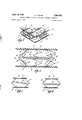
- Fig. l is an isometric view, partly broken away, showing one embodiment of the present invention.
- Fig. 2 is a view in side elevation on an enlarged scale, partly broken away, showing the embodiment of Fig. 1;
- Fig. 3 is a view in side elevation, partly broken away and with parts omitted, of another embodiment of the invention;
- Fig. 4 is a view in side elevation, partly broken away and with parts omitted, of still a further embodiment of l cal connectors 18 are employed to secure the array of coil springs to frame members 10, 12.
- edge stiffener in order tosecure the edge stiffener firmly and permanently in its proper location in the assembly.
- edge' stiifeners commonly employed in 'the past have tended to bend or warp out of the desired vertical plane during compression, leading to bulging use;
- One objectof the present invention is to provide an edge stiffener which can be permanently installed in the spring assembly by the manufacturer, but which can read- Along the edges of the soil spring assembly a plurality of edge stiffeners indicated generally by the numeral 20 are provided, each edge stiffener lying substantially in a 7, single plane which coincides with the plane defined by" the two opposing marginal portions of the frame members 10, 12.
- Each edge stiffener comprises a pair of oppositely disposed bow members 22, 24 formed of flat spring wire having their midportions 26, 28 secured to opposing marginal portions of the frame members 10,12
- Another object is to provide a spring assembly of the type described containing as-plurality of edge stiifeners.
- a further-object is toprovide a modified form necting elements.
- tension spring members 48 are simply removed by disengaging the ends from supplemental connecting elements 44, 46. This permits complete compression of the two bow members 22, 24 to substantially the same ultimate thickness as the coil springs themselves. Upon receipt of the compressed assembly by the customer and its removal from the bale, the tension springs 48, which may beshipped separately, are readily inserted in place,
- tension springs 48. being. connected directly between the terminal portions of the bow members adjacent the joints, the. tension spring in this embodiment being connected between one end of one how member andthe other end of the other bow member.
- each edge stiffener takesthe form of a Pair of separate components 60, each of which consists of a pair of'toggle arms 62, 64 and 66,. 68.
- Each pair of toggle-arms is pivotally joined together to provide joints 70, 72,, and each arm is constructed of flat wire which. is twisted so that the fiat faces, adjacent the free ends of the arms, are
- each arm' form an:
- Each arm is provided with an oifset 78 at the. junction of the two angularly disposed portions.
- Each component 60 also includes a third arm 80 pivotally joined to. the toggle arms at the'pivotal joint and provided with a hole 82 near its free end serving to engage one end of a tension spring 84.
- one component'60 is mounted on a spring assembly by inserting the free ends of its toggle armsendwise. into helical connector 18 which has previously been applied to the marginal portion of the frame. Either. at the same time or subsequently a second component is;
- Tension spring-84 isthen connected between the arms 80, 80 to urge. the toggle arms of both components to expanded position.
- Oifset'portions 78 serve as abutments both. to prevent toggle arms 74, 76 from riding over each other'lengthwise under the influence of tension spring 84 and to engage the adjacent turns of helical connector 18 and thusmaintain each component in its desired position between the frames.
- the abutment of the ends of arms 74 against otfsets 78, 78 of arms 76 ensures that joints In the embodiment shownin; Fig. 4, on the other hand, the tension spring is connected each edge stiffener comprising a.
- firstpair'of angularly disposed toggle arms pivotally joined at their juncture and having their free ends secured to. opposing marginal. portions of said frame members, a second pair of angular- 1y disposed toggle arms pivotally joined at their juncture and having their free ends secured to opposing-marginal portions of saidframe' members,said.
- first and. second pairs being spaced from each otherand lying in a single plane with the angularly disposed arms of each pair extending outwardly away from the angularly disposed arms of the other, and a tension spring removably connected between the pivotal joints of each. pair to urge saidf ra me. members apart, said. edge stifieners being readily collapsible upon removal ofsaid springs.
- each pair of toggle arms is removable. as. a unit from said assembly, the free ends of each pair of. toggle arms. overlapping the'free ends of the opposing pair of toggle.
- a spring assembly asdefined in. claim 3 comprise ing a helical wire connector connecting each set of. over-.
- a spring assembly comprising 111 combination a pair 7 of frame members resiliently maintained in spaced paral-.-
- each edge stiifener comprising a pair of oppositely dist posed bow members, said how members having their mide portions secured to opposing marginal portionsv of said frame members and their endspivotally connected.
- Figs: 5 and 6 may be ornitted from the spring assembly, thus permitting-the assembly to be readily compressed for baling and shipping. 7
- eachv arin' comprising a flat wire member bent at aniobtuse angle at a point spaced from said joint to provide anendr: portion remote from said jointzadapted-to.:be.seeured tofaul. marginal. portion of said? frame member by avhelicalconnector, the Hat faces of said end portion beingsdisposed: at right angles to theplane in which said' arms 'movez" about said joint, said end portion being oifset" froin tlie remaining portion of said arm to provide an: abutment; i and means: for securing a tension spring to said com ponent' adjacent said joint;- 9'.
- a collapsible edge' 3. A spring assembly as defined'in claim 2.
- each toggle arm is made of flat wire,.the flat faces of J the wire in the overlapping ends being disposedat angles to the plane defined by. said arms, eachtoggle arm j is provided with ashoulder at its juncture with the marginal portion of said frame members and theinner one. of.
- each overlapping set of toggle arms has itsfree end abut? 'stifie'nercomponent; a defin d in olaim 8 in which said-.tension 'spring securing means comprises a separate arm pivotally connected to both said toggle arms at said joint.
- a collapsible edge stiffener component for a coil spring assembly comprising a pair of flat resilient metal strips each having a free end and a joint end, each of said strips being formed to have a straight portion adjacent said free end which forms an obtuse angle with a second straight portion adjacent said joint end, means for securing said joint ends together in a pivotal connection, the flat face of said strip adjacent said free end being at right angles to the plane in which said strips are 7 adapted to pivot and means for attaching a tension spring to said component adjacent said joint.
- a spring assembly comprising in combination a pair of frame members resiliently mounted in spaced parallel relationship by a plurality of coil springs interposed therebetween and a plurality of collapsible edge stifieners, each edge stiifener comprising a pair of oppositely disposed components, each said component comprising a pair of flat metal strips, each strip having a first straight portion formed at an obtuse angle to a second straight portion, means to secure the ends of said strips adjacent said first portions together in a pivotal joint, means to secure said second portions of each component to opposing marginal portions of said frame members, said second portions of said oppositely disposed components being arranged in superimposed relationship such that the second portions of one of said components overlap the corresponding second portions of the other component, and a tension spring removably connected between the pivotal joints of each pair of components adapted to urge said frame members, apart, said edge stifieners being readily collapsible on removal of said springs.
Landscapes
- Springs (AREA)
Description
April 19, 1960 D. I. LEVINE SPRING ASSEMBLY AND EDGE STIFFENER COMPONENT THEREFOR Filed June 10, 1958 2 Sheets-Sheet 1 D. l. LEVINE April 19, 1960 SPRING ASSEMBLY AND EDGE STIFFENER COMPONENT THEREFOR Filed June 10, 1958 2 Sheets-Sheet 2 SPRING ASSEMBLY EDGE STIFFENER COMPONENT THEREFOR David I. Levine, Swampscott, Mass., assignor, by mesne assignments, to Spring Products Developing Co., a partnership composed of Florence H. Jacobs and Ida W. Levine, Lynn, Mass.
Application June 10, 1958, Serial No. 741,066
12 Claims. (Cl. 5-261) This invention relates to a spring assembly construction and pertains more specifically to such a construction comprising a pair of frame members resiliently maintained in spaced-apart parallel relation by a plurality of coil springs and provided with one or more collapsible edge stiffeners.
In coil spring assemblies, such as those used in mattresses, seat cushions and the like, it is frequently necessary to employ, in addition to the main coil springs, supplemental stitfeners along the edges of the assembly to resist the unusually high concentration of stresses which occurs at the edges of the assembly in use and to enable the finished article to maintain its shape to the desired extent. However, the manufacture of spring assemblies of the type described and the covering or upholstering of such assemblies to form a finished mattress, seat cushion or the like have. long been separate operations carried out by different manufacturers in different factories. Consequently shipping of the completed spring assembly from the location at which it is produced to the upholsterer or mattress manufacturer has been necessary. Shipment of the bulky spring assembly, in order to be economically feasible, has necessitated compression of the assemblies to a very small fraction of their normal uncompressed thickness and baling of the assemblies in 3 this compressed condition. The presence of edge stiffener's makes the bailing operation very difiicult or impossible to carry out, both because of the increased resistance to compression which the edge stiifeners display over and above that displayed by the coil springs and because of the impossibility in many cases of compressing the edge stiifeners to the same extent as conventional coil springs.
While this problem can be solved by leaving the edge stiffeners out of-the assembly and shipping them separately to the mattress or cushion manufacturer for insertion into the assembly immediately prior to covering, this solution has in the past not proved entirely satisfacof edge stiffener which may readily be inserted by a mattress manufacturer without the use of any special tools or machinery.
Still another object is to provide a spring assembly of the type described having an edge stifi'ener which lies essentially in a single plane and which remains in that plane without warping during compression.
Other and further objects will be apparent from the drawing and from the description which follows.
In the drawings:
Fig. l is an isometric view, partly broken away, showing one embodiment of the present invention;
Fig. 2 is a view in side elevation on an enlarged scale, partly broken away, showing the embodiment of Fig. 1; Fig. 3 is a view in side elevation, partly broken away and with parts omitted, of another embodiment of the invention;
Fig. 4 is a view in side elevation, partly broken away and with parts omitted, of still a further embodiment of l cal connectors 18 are employed to secure the array of coil springs to frame members 10, 12.
to'ry*because it has necessitated the acquisition and use of special tools and/or machinery by the mattress. or-
cushion manufacturer in order tosecure the edge stiffener firmly and permanently in its proper location in the assembly. Moreover, the edge' stiifeners commonly employed in 'the past have tended to bend or warp out of the desired vertical plane during compression, leading to bulging use;
One objectof the present invention is to provide an edge stiffener which can be permanently installed in the spring assembly by the manufacturer, but which can read- Along the edges of the soil spring assembly a plurality of edge stiffeners indicated generally by the numeral 20 are provided, each edge stiffener lying substantially in a 7, single plane which coincides with the plane defined by" the two opposing marginal portions of the frame members 10, 12. Each edge stiffener comprises a pair of oppositely disposed bow members 22, 24 formed of flat spring wire having their midportions 26, 28 secured to opposing marginal portions of the frame members 10,12
by means of helical connectors 18, 18. The end portions 30, 32, 34, 36 of the respective bow members extend toward each other, being twisted through 90 at their ends 38, 38 and pivotally joined to each other at their junc- . tures 40, 42 to provide a pair of angularly disposed toggle arms having their free ends secured to opposing marginal portions of the frame members. This arrangement provides in effect a pair of oppositely outwardly extendingtoggle joints spaced from each other and lying in the plane defined by frame members 10, 12. In the embodiment shown in Figs. 1 and 2 a pair of supplemental connectingelements 44, 46 are provided which are pivotally connected to joints 40, 42 respectively. Connected between the ends of said supplemental connecting elements 44, 46 is a tension coil spring 48 having its ends hooked through suitableholes in the supplemental .con-
or-sagging of the edge of the finished article in ily be rendered inoperative so as to permit the assembly td be compressed and baled for shipment and which then can .be rendered operative by the customer without the necessity for the use of any special tools or machinery.
Another object is to provide a spring assembly of the type described containing as-plurality of edge stiifeners.
which are rendered readily collapsible by removal of a single part, which part may be replaced to activate the stiifener without the necessity for using any special tools or skill, A further-object is toprovidea modified form necting elements. By choice of a tension spring of suitable length and strength, the midportions 26, 28 of how members 22, 24 may be urged apart with the desired force to provide the necessary stiffening for the edge of the assembly.
In order to compress and bale the spring assembly for shipment, tension spring members 48 are simply removed by disengaging the ends from supplemental connecting elements 44, 46. This permits complete compression of the two bow members 22, 24 to substantially the same ultimate thickness as the coil springs themselves. Upon receipt of the compressed assembly by the customer and its removal from the bale, the tension springs 48, which may beshipped separately, are readily inserted in place,
Patented Apr. 19, 19 0 g manually without the necessity for any special tools or 'skill so that the device is immediately rendered operative.
In another embodiment of'the device as shown in Fig.
3, supplemental connectingelements 4-4, 46. are omitted,=;
directly between opposite ends of the same bow member. All three embodiments provide essentially the same results and may be used in the same way.
In the modified embodiment shown. in Figs. 5 and 6 each edge stiffener takesthe form of a Pair of separate components 60, each of which consists ofa pair of'toggle arms 62, 64 and 66,. 68. Each pair of toggle-arms is pivotally joined together to provide joints 70, 72,, and each arm is constructed of flat wire which. is twisted so that the fiat faces, adjacent the free ends of the arms, are
disposed at right angles to the plane defined by the pair of arms, i.e. the plane in which the arms move.
The end portions 74, 74, 76, 76 of each arm' form an:
obtuse angle with the portions adjacent the pivotal joint. Each arm is provided with an oifset 78 at the. junction of the two angularly disposed portions. Each component 60 also includes a third arm 80 pivotally joined to. the toggle arms at the'pivotal joint and provided with a hole 82 near its free end serving to engage one end of a tension spring 84.
In use, one component'60 is mounted on a spring assembly by inserting the free ends of its toggle armsendwise. into helical connector 18 which has previously been applied to the marginal portion of the frame. Either. at the same time or subsequently a second component is;
mounted on the assembly spaced from the first with its toggle joint extending outwardly in a direction opposite to the first, as shown in Fig. 5 The free end portions 74, 74 ofone pair of toggle arms overlap, the free end portions 76, 76 of the other pair of toggle arms adjacent the marginal portions of the frame,.while the ends of arms 74, 74 abut against the ofiset shoulder portions 78,
78 of the other pair of arms 76, 76. Tension spring-84 isthen connected between the arms 80, 80 to urge. the toggle arms of both components to expanded position. Oifset'portions 78 serve as abutments both. to prevent toggle arms 74, 76 from riding over each other'lengthwise under the influence of tension spring 84 and to engage the adjacent turns of helical connector 18 and thusmaintain each component in its desired position between the frames. Furthermore, the abutment of the ends of arms 74 against otfsets 78, 78 of arms 76 ensures that joints In the embodiment shownin; Fig. 4, on the other hand, the tension spring is connected each edge stiffener comprising a. firstpair'of angularly disposed toggle arms pivotally joined at their juncture and having their free ends secured to. opposing marginal. portions of said frame members, a second pair of angular- 1y disposed toggle arms pivotally joined at their juncture and having their free ends secured to opposing-marginal portions of saidframe' members,said. first and. second pairs being spaced from each otherand lying in a single plane with the angularly disposed arms of each pair extending outwardly away from the angularly disposed arms of the other, and a tension spring removably connected between the pivotal joints of each. pair to urge saidf ra me. members apart, said. edge stifieners being readily collapsible upon removal ofsaid springs.
2. A spring assembly as defined in claim 1. in which? each pair of toggle arms is removable. as. a unit from said assembly, the free ends of each pair of. toggle arms. overlapping the'free ends of the opposing pair of toggle.
arms.
ting against the shoulder of the overlappingarm.
4. A spring assembly asdefined in. claim 3 comprise ing a helical wire connector connecting each set of. over-.
lapping toggle arms to the marginal portionof theframef V I n e I s a 5. A spring assembly comprising 111 combination a pair 7 of frame members resiliently maintained in spaced paral-.-
lel'relation by a plurality of coil springs interposed there:
between and a plurality of collapsible edge stifieners, each edge stiifener comprising a pair of oppositely dist posed bow members, said how members having their mide portions secured to opposing marginal portionsv of said frame members and their endspivotally connected. to
each other to provide a pair of oppositely outwardly extending toggle joints lying in a single plane, anda tensionspring removablyv connected between said pair of' toggle joints to urge said frame members apart, said edge eners being readily collapsible upon removal of said.
springs. Y
70,. 72. are' maintained spaced" apart. by a.- predetermined distance so that a uniform degree of'stiifness'is provided ;by the tension of spring 84.
It will be understood that, as in the case of the embodiments shown in Figs. 3 and 4, the arms 80, 80 of the components shown in Figs. 5 and 6 may be replaced by a direct connection of spring 84' to the toggle arms adjacent'their pivotal joint. 3
The components shown in Figs: 5 and 6 may be ornitted from the spring assembly, thus permitting-the assembly to be readily compressed for baling and shipping. 7
After the spring assemblies have been removed; from the bale and. allowed to expand the components may be mounted in place as described above without'the necessity for any special tools or machinery to provide the desired edge stiffeners.
This application is a continuation-in-part of my copending application Ser. No. 720,683, filed March 11,
1958, now abandoned;
Although specific embodiments" of the invention have been described herein, itis not intended to limit the invehtion solely thereto, but to include-all of theobvious 6. A spring assembly asdefined in claim-5, inwhich: each said tension spring is-.pivotally. connectedto each.
said joint.
, 7. A spring assembly asdefinedinclaimfi in which each end of each said tension springis-directly connected to a bow member adjacent onesaid joint.
8:. A collapsible edge stifiener oomponent'for: a coil: spring assembly having a. pair of. frame members T581173 iently maintained-in spaced parallel relation by a'plurality.
of coil springs interposed therebetween, each component:
comprising a pair of toggle arms pivotally joinedatogether,
eachv arin' comprisinga flat wire member bent at aniobtuse angle at a point spaced from said joint to provide anendr: portion remote from said jointzadapted-to.:be.seeured tofaul. marginal. portion of said? frame member by avhelicalconnector, the Hat faces of said end portion beingsdisposed: at right angles to theplane in which said' arms 'movez" about said joint, said end portion being oifset" froin tlie remaining portion of said arm to provide an: abutment; i and means: for securing a tension spring to said com ponent' adjacent said joint;- 9'. A collapsible edge' 3. A spring assembly as defined'in claim 2. in which each toggle arm is made of flat wire,.the flat faces of J the wire in the overlapping ends being disposedat angles to the plane defined by. said arms, eachtoggle arm j is provided with ashoulder at its juncture with the marginal portion of said frame members and theinner one. of.
' each overlapping set of toggle arms has itsfree end abut? 'stifie'nercomponent; a defin d in olaim 8 in which said-.tension 'spring securing means comprises a separate arm pivotally connected to both said toggle arms at said joint.
10. A collapsible edge stiffener component for a coil spring assembly comprising a pair of flat resilient metal strips each having a free end and a joint end, each of said strips being formed to have a straight portion adjacent said free end which forms an obtuse angle with a second straight portion adjacent said joint end, means for securing said joint ends together in a pivotal connection, the flat face of said strip adjacent said free end being at right angles to the plane in which said strips are 7 adapted to pivot and means for attaching a tension spring to said component adjacent said joint.
11. The collapsible edge stiffener component as defined in claim 10 wherein said tension spring attaching means includes a link pivotally connected to both of said strips at said joint.
12. A spring assembly comprising in combination a pair of frame members resiliently mounted in spaced parallel relationship by a plurality of coil springs interposed therebetween and a plurality of collapsible edge stifieners, each edge stiifener comprising a pair of oppositely disposed components, each said component comprising a pair of flat metal strips, each strip having a first straight portion formed at an obtuse angle to a second straight portion, means to secure the ends of said strips adjacent said first portions together in a pivotal joint, means to secure said second portions of each component to opposing marginal portions of said frame members, said second portions of said oppositely disposed components being arranged in superimposed relationship such that the second portions of one of said components overlap the corresponding second portions of the other component, and a tension spring removably connected between the pivotal joints of each pair of components adapted to urge said frame members, apart, said edge stifieners being readily collapsible on removal of said springs.
References Cited in the file of this patent UNITED STATES PATENTS 2,509,831 Martin May 30, 1950 FOREIGN PATENTS 18,982 Great Britain Aug. 27, 1896 808,760 France NOV. 24, 1936 728,882 Great Britain Apr. 27, 1955 UNITED STATES PATENT OFFICE CERTIFICATE OF CORRECTION Patent No. 2,932, 832 April 19, 1960 David I. Levine It is herebjr certified that error appears in the-printed specification of the above numbered patent requiring correction and that the said Letters Patent should read as corrected below.
Column 6, list of References Cited, under UNITED STATES PATENTS, between lines 19 and 20 insert the following:
807,314 Pepple --Dec. 12 1905 Signed and sealed this 20th day of September 1960.
(SEAL) Attest:
KARL H, AXLINE ROBERT C. WATSON Attesting Officer I Commissioner of Patents
Priority Applications (1)
| Application Number | Priority Date | Filing Date | Title |
|---|---|---|---|
| US741066A US2932832A (en) | 1958-06-10 | 1958-06-10 | Spring assembly and edge stiffener component therefor |
Applications Claiming Priority (1)
| Application Number | Priority Date | Filing Date | Title |
|---|---|---|---|
| US741066A US2932832A (en) | 1958-06-10 | 1958-06-10 | Spring assembly and edge stiffener component therefor |
Publications (1)
| Publication Number | Publication Date |
|---|---|
| US2932832A true US2932832A (en) | 1960-04-19 |
Family
ID=24979239
Family Applications (1)
| Application Number | Title | Priority Date | Filing Date |
|---|---|---|---|
| US741066A Expired - Lifetime US2932832A (en) | 1958-06-10 | 1958-06-10 | Spring assembly and edge stiffener component therefor |
Country Status (1)
| Country | Link |
|---|---|
| US (1) | US2932832A (en) |
Cited By (7)
| Publication number | Priority date | Publication date | Assignee | Title |
|---|---|---|---|---|
| US3022521A (en) * | 1960-08-26 | 1962-02-27 | Eclipse Sleep Products Inc | Border stabilizers |
| US3049156A (en) * | 1959-03-31 | 1962-08-14 | Eclipse Sleep Products Inc | Machine and method for forming wire units |
| US3121882A (en) * | 1962-10-19 | 1964-02-25 | Eclipse Sleep Products Inc | Stabilizers |
| US3121883A (en) * | 1962-02-14 | 1964-02-25 | Eclipse Sleep Products Inc | Stabilizers |
| US3206759A (en) * | 1964-03-18 | 1965-09-14 | Eclipse Sleep Products Inc | Stabilizers |
| US3353195A (en) * | 1966-12-14 | 1967-11-21 | Eclipse Sleep Products Inc | Border stabilizers for inner spring units |
| US4856765A (en) * | 1986-10-09 | 1989-08-15 | Masahiro Kohno | Spring apparatus |
Citations (4)
| Publication number | Priority date | Publication date | Assignee | Title |
|---|---|---|---|---|
| GB189618982A (en) * | 1896-08-27 | 1896-10-03 | Otto Schroeder | Improvements in and connected with Supports for Upholstered Articles. |
| FR808760A (en) * | 1935-10-31 | 1937-02-15 | Improvements to the means of suspension of seats, in particular vehicle seats | |
| US2509831A (en) * | 1949-05-03 | 1950-05-30 | Eclipse Sleep Products Inc | Stabilizer for inner spring units |
| GB728882A (en) * | 1953-08-31 | 1955-04-27 | Eclipse Sleep Products Inc | Border reinforcing springs for inner spring units |
-
1958
- 1958-06-10 US US741066A patent/US2932832A/en not_active Expired - Lifetime
Patent Citations (4)
| Publication number | Priority date | Publication date | Assignee | Title |
|---|---|---|---|---|
| GB189618982A (en) * | 1896-08-27 | 1896-10-03 | Otto Schroeder | Improvements in and connected with Supports for Upholstered Articles. |
| FR808760A (en) * | 1935-10-31 | 1937-02-15 | Improvements to the means of suspension of seats, in particular vehicle seats | |
| US2509831A (en) * | 1949-05-03 | 1950-05-30 | Eclipse Sleep Products Inc | Stabilizer for inner spring units |
| GB728882A (en) * | 1953-08-31 | 1955-04-27 | Eclipse Sleep Products Inc | Border reinforcing springs for inner spring units |
Cited By (7)
| Publication number | Priority date | Publication date | Assignee | Title |
|---|---|---|---|---|
| US3049156A (en) * | 1959-03-31 | 1962-08-14 | Eclipse Sleep Products Inc | Machine and method for forming wire units |
| US3022521A (en) * | 1960-08-26 | 1962-02-27 | Eclipse Sleep Products Inc | Border stabilizers |
| US3121883A (en) * | 1962-02-14 | 1964-02-25 | Eclipse Sleep Products Inc | Stabilizers |
| US3121882A (en) * | 1962-10-19 | 1964-02-25 | Eclipse Sleep Products Inc | Stabilizers |
| US3206759A (en) * | 1964-03-18 | 1965-09-14 | Eclipse Sleep Products Inc | Stabilizers |
| US3353195A (en) * | 1966-12-14 | 1967-11-21 | Eclipse Sleep Products Inc | Border stabilizers for inner spring units |
| US4856765A (en) * | 1986-10-09 | 1989-08-15 | Masahiro Kohno | Spring apparatus |
Similar Documents
| Publication | Publication Date | Title |
|---|---|---|
| US2932832A (en) | Spring assembly and edge stiffener component therefor | |
| US2163359A (en) | Seat back and the like and method of forming | |
| US1842054A (en) | Chair | |
| US2491784A (en) | Stadium seat | |
| US2697863A (en) | Pin fastener for furniture covers and the like | |
| US3653081A (en) | Mattress corner construction | |
| US3057613A (en) | Spring assemblies for seats, settees, beds and the like | |
| US2040463A (en) | Seat covering device | |
| US4101992A (en) | Spring assembly with reinforcement | |
| US3982290A (en) | Mattress edge stiffener | |
| US3055021A (en) | Upholstered spring assembly | |
| US2227685A (en) | Reinforced fabric and method of making same | |
| US3147495A (en) | Bed bottom, seat or back | |
| US2102066A (en) | Edging for spring assemblies for upholstery | |
| US1894831A (en) | Rolled edge construction | |
| US2557671A (en) | Mcdonald | |
| US1719532A (en) | Chair | |
| US2998971A (en) | Border wire assembly for spring seat and back assemblies | |
| US3356359A (en) | Prestressed furniture spring | |
| US2318583A (en) | Suspension unit | |
| US2284108A (en) | Spring seat | |
| US2293323A (en) | Spring seat construction | |
| US2736367A (en) | Spring seat for a sofa-bed | |
| US2613734A (en) | Hopkes | |
| US201911A (en) | Improvement in spring-pillows |