US2930833A - Electrical conductor having transposed conducting members - Google Patents
Electrical conductor having transposed conducting members Download PDFInfo
- Publication number
- US2930833A US2930833A US519108A US51910855A US2930833A US 2930833 A US2930833 A US 2930833A US 519108 A US519108 A US 519108A US 51910855 A US51910855 A US 51910855A US 2930833 A US2930833 A US 2930833A
- Authority
- US
- United States
- Prior art keywords
- conductor
- members
- conducting
- electrical
- electrical conductor
- Prior art date
- Legal status (The legal status is an assumption and is not a legal conclusion. Google has not performed a legal analysis and makes no representation as to the accuracy of the status listed.)
- Expired - Lifetime
Links
Images

Classifications
-
- H—ELECTRICITY
- H01—ELECTRIC ELEMENTS
- H01B—CABLES; CONDUCTORS; INSULATORS; SELECTION OF MATERIALS FOR THEIR CONDUCTIVE, INSULATING OR DIELECTRIC PROPERTIES
- H01B7/00—Insulated conductors or cables characterised by their form
- H01B7/30—Insulated conductors or cables characterised by their form with arrangements for reducing conductor losses when carrying alternating current, e.g. due to skin effect
- H01B7/306—Transposed conductors
Definitions
- This invention relates to electrical conductors and more particularly to electrical conductors each comprising a plurality of transposed conducting elements and to methods of making them.
- transposed conducting elements is used to refer to a plurality of conducting elements whose positions are shifted relative to each other and to an axis of the conductor.
- the shifting may be continuous along the length of the conductor or it may occur at discrete intervals.
- the transpositions may take the form of frequent shifting of large numbers of conducting strands as in the case of Litzendraht wire, or it may be an orderly change of position of a few conductors such as, for example, the type shown and described in my copending United States patent application Serial No. 366,510 which was filed July 7, 1953, now Patent 2,812,502, issued on November 5, 1957.
- the current distribution which is substantially uniform throughout the cross-sectional area of the conductor at very low frequencies becomes nonuniform as frequency is increased.
- the current is substantially uniformly distributed throughout the cross-sectional area of the conductor and the resistance of the conductor and hence the conductor loss is at a minimum.
- the current density becomes a maximum at that surface of the conductor which is exposed to the main field of the waves, which, in the present example, is the outer surface, and decreases as distance from the field increases, i.e., toward the center of the conductor.
- the rate at which the current density decreases is dependent upon the frequency and the material of the conductor and, for most conducting materials, at high frequency the current density at the center of the conductor becomes negligible while the current density at the conductor surface is a maximum.
- This phenomenon is commonly known as skin effect and a skin depth is defined as the distance measured inwardly from the surface of the conductor in which the current in the conductor will decrease by one neper, i.e., the current density becomes ing quite large at the higher frequencies, necessitating.
- the alternating-current resistance of a conductor to high frequencies can be substantially reduced if the conductor is formed of a number of conducting elements or members connected in parallel and transposed often so that each conductor receives its share of exposure to the main field. This amounts to forcing the current to distribute itself over the entire cross-sectional area of the composite of individual conducting elements, thereby increasing the total current carrying area. It follows then that the alternating-current resistance is decreased substantially and the frequency dependency of the alternating-current resistance is likewise decreased.
- Litzendraht wire which, while effective at lower frequencies, suffers from many disadvantages at the higher frequencies in that, first, each individual strand of wire must be insulated from all of the others, requiring great care in fabrication especially for operation at the higher frequencies; second, for effectiveness at the higher frequencies the diameter of the individual strands of wire must be made so small that of necessity there are great sacrifices in strength and ruggedness; third, with the large number of individual strands involved, proper transposition is exceedingly difiicult to achieve especially when use at high frequencies is contemplated which requires numerous transpositions at very short intervals.
- an electrical conductor having transp'osedconducting elements is provided which a greatimprovement in many respects over other known transposed conductors.
- the conductor of the present invention is of particular value in applications which require the conductor to have a large degree of mechanical strength.
- a plurality of solid core members of conducting material are joined by insulating joints to form an elongated core member.
- a thin sleeve of conducting material surrounds each of the core members and is insulated therefrom.
- Bridge members are provided at the joints to electrically connect the sleeves on either side of the joint to the core members on the other side, thereby effecting electrical transpositions-
- Fig. 1 is a perspective view of a preferred embodiment of my invention
- FIG. 2 is a sectional elevation view of the conductor of Fig. 3 is a perspective view of an element of the conductor of Figs. 1 and 2;
- Fig. 4 is a perspective view of an alternative form of the element of Fig. 3;
- Fig. 5 is a sectional elevation view of another preferred embodiment of the invention.
- Fig. 6 is a section-a1 elevation view of still another embodiment of the invention.
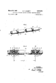
- Conductor 11 comprises a plurality of substantially identical sections 12 of conducting and insulating material. which are joined together in a manner which will be more fully described hereinafter by insulating members 13, forming an elongated structure of conducting sections separated by insulating sections. Electrical conductivity throughout the length of the structure and electrical transpositions of the conducting elements are accomplished in a manner to be explained hereinafter by bridge members 14 of conducting material which are disposed along the length of the structure at the insulated joints.
- Each section 12 comprises an elongate core member 15 of conducting material having a circular cross section.
- a hollow cylindrical member 17 of conducting material Surrounding core member 15 and insulated therefrom by an insulating layer 16 is a hollow cylindrical member 17 of conducting material which is preferably the same material as that of member 15. As is apparent in Fig. 2, insulating layer 16 is slightly shorter in length than member 15 so that member 15 is exposed for a short distance at each end. Cylindrical member 17 in turn is slightly shorter in length than insulating layer 16. In order that each section 12 may be mechanically joined to adjacent sections 12, there is formed at each end of member 15 a threaded socket 18 which is preferably concentric with and extends for a short distance into member 15.
- a plug member 13 of insulating material having threaded portions 19 and 21 and a centrally located collar 22 of a diameter approximating that of members 15 is screwed into adjacent ends of each pair of members 15, thereby forming an insulated mechanical connection between adjacent sections 12.
- Member 13 may be of any suitable material exhibiting high mechanical strength and electrical insulating properties.
- bridge members 14 of conducting material connect member 15 of one section 12 to cylindrical member 17 of the adjacent section 12 across the insulated joint formed by plug member 13 as best seen in Pig. 2. It will be apparent from examination of Fig. 2 that electrical current which is being carried in the outer conducting member 17 of any section 12 is carried by the inner conducting member 15 of the adjacent section 12, thereby effecting an electrical transposition of the conducting elements.
- Bridge members 14 may be of any suitable shape, such as,.for example, the configurations shown in Figs. 3 and 4, and are preferably bonded to members 15 and 17 by brazing or welding at their exposed ends. Alternatively members 14 may be secured in place by any of a number of suitable ways, such as, for example, a band or clamp (not shown) which is fastened tightly around bridge members 14.
- transpositions of conducting elements in a conductor depends to a considerable extent upon a judicious selection of the transposition interval, that is, the distance 1 between the points a and b in Fig. 2. It is desirable to transpose often enough to insure a substantial reduction in losses, yet, on the other hand, in the interests of ease and low cost of fabrication, it is desirable that the conducting elements be transposed no more frequently than is necessary. As long as the currents carried by the conducting elements are approximately equal, losses will be minimized, hence it is necessary to transpose only often enough to maintain this condition of approximate equality of currents in the conducting elements.
- the particular embodiments shown are neither to scale nor proportion, inasmuch as the transposition interval may be quite long as compared to the length of the conductor over which the transposition is accomplished.
- Fig. 5 there is shown a second preferred embodiment of the present invention in which the insulating plugs 13 of the embodiment of Figs. 1 and 2 are eliminated.
- the conductor 23 of Fig. 5 comprises an elongated continuous core member 24 of conducting material of circular cross section which has an insulating coating or layer 25 on its surface.
- a plurality of cylindrical conducting members 26 are disposed along the length of member 24 and are concentric therewith. The members 26 are maintained in spaced and insulated relationship by suitable spacers 27 of insulating material.
- Disposed about each of the members 26 and insulated therefrom by insulating layer 28 is a cylindrical member 29 of conducting material, preferably the same as the material of member 26. It is readily apparent in Fig. 5 that insulating layer 28 is slightly shorter than member 26 and member 29 in turn is slightly shorter than layer 28.
- Conductor 23 differs from conductor 11 of Figs. 1 and 2 in that core member 24 is a continuous electrical conductor which makes conductor 23- especially useful in those applications where transmission of power current along with the high frequency currents is desired. Such a situation arises for instance where long distance transmission requires the use of remote amplification or repeater stages which might be inaccessible.
- the power necessary to operate the relay station is carried by the cable which also carries the signal being transmitted.
- Core member 24 obviously can be used to carry a portion of the signal or high frequency energy if desired.
- the conducting members 26 and 29 can advantageously be of a thickness which is of the magnitude of a skin depth, thus greatly descreasing the losses resulting from eddy currents.
- a composite conductor 32 which has, instead of a conducting core as was the case with conductor 23, a core 33 of insulating material.
- conductor 32 may be identical to conductor 23, with the exception that insulating layer 25 is no longer necessary.
- Those elements in conductor 32 which are the same as those of conductor 23 have been identified by the same reference numerals.
- a low-loss electrical conductor having a pair of adjacent sections of inner members of conducting material disposed along the length of the conductor, an outer cylindrical member of conducting material surrounding each of said inner members of shorter length than its corresponding inner member so that adjacent portions of each inner member extend beyond the adjacent ends of the outer members, means for insulating said outer member from said inner member, a plug of insulating material having a central portion and a reduced diameter portion on either side of said central portion, said reduced diameter portions being inserted into the ends of said adjacent inner members for electrically separating and mechanically joining said adjacent inner members, a first rigid bridge-shaped member of conducting material having one of the bridge ends thereof connectively surrounding a substantial portion of the circumference of the outer member of a first of said sections and the other bridge end thereof connectively surrounding a substantial portion of said extending portion of the inner member of the section adjacent to said first section, and a second rigid bridgeshaped member of conducting material having one of the bridge ends thereof connectively surrounding a substantial portion of the outer member of said adjacent section and the other bridge end thereof connectively surrounding
- a low-loss electrical conductor as claimed in claim 1, wherein said reduced diameter portions are threaded and each of said inner members has a threaded socket at each end to receive said reduced diameter portion.
Description
March 29, 1960 w. H. DOHERTY ELECTRICAL CONDUCTOR HAVING TRANSPOSED CONDUCTING MEMBERS Filed June 30, 1955 2 Sheets-Sheet 1 INVENTOR W H. DOHE/PTY By I ATTORNEY j 1960 w. H. DOHERTY 2,930,833
ELECTRICAL CONDUCTOR HAVING TRANSPOSED CONDUCTING MEMBERS Filed June 30, 1955 2. Sheets-Sheet 2 INVENTOR W h. DOHERTY ATTORNEY ELECTRICAL CONDUCTOR HAVING TRANS- POSED CONDUCTING MEMBERS William H. Doherty, Summit, NJ., assiguor to Bell Telephone Laboratories, Incorporated, New York, N.Y., a corporation of New York Application June 30, 1955, Serial No. 519,103
2 Claims. (Cl. 174-34) This invention relates to electrical conductors and more particularly to electrical conductors each comprising a plurality of transposed conducting elements and to methods of making them.
The term transposed conducting elements is used to refer to a plurality of conducting elements whose positions are shifted relative to each other and to an axis of the conductor. The shifting may be continuous along the length of the conductor or it may occur at discrete intervals. Also the transpositions may take the form of frequent shifting of large numbers of conducting strands as in the case of Litzendraht wire, or it may be an orderly change of position of a few conductors such as, for example, the type shown and described in my copending United States patent application Serial No. 366,510 which was filed July 7, 1953, now Patent 2,812,502, issued on November 5, 1957.
It is an object of this invention to simplify the construction of electrical conductors having transpositions.
It is another object of this invention to provide an electrical conductor, the alternating-current resistance of which is less dependent upon frequency changes than that of conventional conductors.
In the transmission of electromagnetic waves, the current distribution which is substantially uniform throughout the cross-sectional area of the conductor at very low frequencies becomes nonuniform as frequency is increased. Consider, for example, the case of a solid conductor to which are applied waves of increasing fre quency. At direct-current and at very low alternatingcurrent frequencies the current is substantially uniformly distributed throughout the cross-sectional area of the conductor and the resistance of the conductor and hence the conductor loss is at a minimum. As the frequency is increased, the current density becomes a maximum at that surface of the conductor which is exposed to the main field of the waves, which, in the present example, is the outer surface, and decreases as distance from the field increases, i.e., toward the center of the conductor. The rate at which the current density decreases is dependent upon the frequency and the material of the conductor and, for most conducting materials, at high frequency the current density at the center of the conductor becomes negligible while the current density at the conductor surface is a maximum. This phenomenon is commonly known as skin effect and a skin depth is defined as the distance measured inwardly from the surface of the conductor in which the current in the conductor will decrease by one neper, i.e., the current density becomes ing quite large at the higher frequencies, necessitating.
rates atent Fat-tented MaruZfi, 1950 frequent amplification of the signal along the transmission path.
It has long been recognized that the alternating-current resistance of a conductor to high frequencies can be substantially reduced if the conductor is formed of a number of conducting elements or members connected in parallel and transposed often so that each conductor receives its share of exposure to the main field. This amounts to forcing the current to distribute itself over the entire cross-sectional area of the composite of individual conducting elements, thereby increasing the total current carrying area. It follows then that the alternating-current resistance is decreased substantially and the frequency dependency of the alternating-current resistance is likewise decreased.
One well known example of a composite conductor which utilizes the foregoing principles is Litzendraht wire which, while effective at lower frequencies, suffers from many disadvantages at the higher frequencies in that, first, each individual strand of wire must be insulated from all of the others, requiring great care in fabrication especially for operation at the higher frequencies; second, for effectiveness at the higher frequencies the diameter of the individual strands of wire must be made so small that of necessity there are great sacrifices in strength and ruggedness; third, with the large number of individual strands involved, proper transposition is exceedingly difiicult to achieve especially when use at high frequencies is contemplated which requires numerous transpositions at very short intervals.
In accordance with the present invention, an electrical conductor having transp'osedconducting elements is provided which a greatimprovement in many respects over other known transposed conductors. The conductor of the present invention is of particular value in applications which require the conductor to have a large degree of mechanical strength. In an illustrative embodiment of the invention, a plurality of solid core members of conducting material are joined by insulating joints to form an elongated core member. A thin sleeve of conducting material surrounds each of the core members and is insulated therefrom. Bridge members are provided at the joints to electrically connect the sleeves on either side of the joint to the core members on the other side, thereby effecting electrical transpositions- The invention will be more readily understood by referring to the following description in conjunction with the accompanying drawings, in which:
Fig. 1 is a perspective view of a preferred embodiment of my invention;
F Fig. 2 is a sectional elevation view of the conductor of Fig. 3 is a perspective view of an element of the conductor of Figs. 1 and 2;
Fig. 4 is a perspective view of an alternative form of the element of Fig. 3;
Fig. 5 is a sectional elevation view of another preferred embodiment of the invention; and
Fig. 6 is a section-a1 elevation view of still another embodiment of the invention.
Turning now to Figs. 1 and 2 there is shown by way of example a composite electrical conductor 11 having a plurality of transpositions along its length. Conductor 11 comprises a plurality of substantially identical sections 12 of conducting and insulating material. which are joined together in a manner which will be more fully described hereinafter by insulating members 13, forming an elongated structure of conducting sections separated by insulating sections. Electrical conductivity throughout the length of the structure and electrical transpositions of the conducting elements are accomplished in a manner to be explained hereinafter by bridge members 14 of conducting material which are disposed along the length of the structure at the insulated joints. Each section 12 comprises an elongate core member 15 of conducting material having a circular cross section. Surrounding core member 15 and insulated therefrom by an insulating layer 16 is a hollow cylindrical member 17 of conducting material which is preferably the same material as that of member 15. As is apparent in Fig. 2, insulating layer 16 is slightly shorter in length than member 15 so that member 15 is exposed for a short distance at each end. Cylindrical member 17 in turn is slightly shorter in length than insulating layer 16. In order that each section 12 may be mechanically joined to adjacent sections 12, there is formed at each end of member 15 a threaded socket 18 which is preferably concentric with and extends for a short distance into member 15. A plug member 13 of insulating material having threaded portions 19 and 21 and a centrally located collar 22 of a diameter approximating that of members 15 is screwed into adjacent ends of each pair of members 15, thereby forming an insulated mechanical connection between adjacent sections 12. Member 13 may be of any suitable material exhibiting high mechanical strength and electrical insulating properties.
In order that electrical conductivity may be maintained throughout the length of the conductor 11 and so that electrical transpositions may be effected, bridge members 14 of conducting material connect member 15 of one section 12 to cylindrical member 17 of the adjacent section 12 across the insulated joint formed by plug member 13 as best seen in Pig. 2. It will be apparent from examination of Fig. 2 that electrical current which is being carried in the outer conducting member 17 of any section 12 is carried by the inner conducting member 15 of the adjacent section 12, thereby effecting an electrical transposition of the conducting elements. Bridge members 14 may be of any suitable shape, such as,.for example, the configurations shown in Figs. 3 and 4, and are preferably bonded to members 15 and 17 by brazing or welding at their exposed ends. Alternatively members 14 may be secured in place by any of a number of suitable ways, such as, for example, a band or clamp (not shown) which is fastened tightly around bridge members 14.
The effectiveness of transpositions of conducting elements in a conductor depends to a considerable extent upon a judicious selection of the transposition interval, that is, the distance 1 between the points a and b in Fig. 2. It is desirable to transpose often enough to insure a substantial reduction in losses, yet, on the other hand, in the interests of ease and low cost of fabrication, it is desirable that the conducting elements be transposed no more frequently than is necessary. As long as the currents carried by the conducting elements are approximately equal, losses will be minimized, hence it is necessary to transpose only often enough to maintain this condition of approximate equality of currents in the conducting elements. In the drawings of the present invention, the particular embodiments shown are neither to scale nor proportion, inasmuch as the transposition interval may be quite long as compared to the length of the conductor over which the transposition is accomplished.
In Fig. 5 there is shown a second preferred embodiment of the present invention in which the insulating plugs 13 of the embodiment of Figs. 1 and 2 are eliminated. The conductor 23 of Fig. 5 comprises an elongated continuous core member 24 of conducting material of circular cross section which has an insulating coating or layer 25 on its surface. A plurality of cylindrical conducting members 26 are disposed along the length of member 24 and are concentric therewith. The members 26 are maintained in spaced and insulated relationship by suitable spacers 27 of insulating material. Disposed about each of the members 26 and insulated therefrom by insulating layer 28 is a cylindrical member 29 of conducting material, preferably the same as the material of member 26. It is readily apparent in Fig. 5 that insulating layer 28 is slightly shorter than member 26 and member 29 in turn is slightly shorter than layer 28.
As was the case with conductor 11 of Figs. 1 and 2, electrical conductivity is maintained between members 26 and 29 and transpositions are effected by bridge members 31 of conducting material which may be identical to bridge members 14 of Figs. 1 and 2, or they may be of any suitable configuration. Members 31 are bonded to the conducting elements 26 and 29 by brazing or by other suitable means to form a strong mechanical and electrical connection. Conductor 23 differs from conductor 11 of Figs. 1 and 2 in that core member 24 is a continuous electrical conductor which makes conductor 23- especially useful in those applications where transmission of power current along with the high frequency currents is desired. Such a situation arises for instance where long distance transmission requires the use of remote amplification or repeater stages which might be inaccessible. In such case the power necessary to operate the relay station is carried by the cable which also carries the signal being transmitted. Core member 24 obviously can be used to carry a portion of the signal or high frequency energy if desired. In such a case, the conducting members 26 and 29 can advantageously be of a thickness which is of the magnitude of a skin depth, thus greatly descreasing the losses resulting from eddy currents.
In Fig. 6 there is shown a composite conductor 32 which has, instead of a conducting core as was the case with conductor 23, a core 33 of insulating material. In all other respects, conductor 32 may be identical to conductor 23, with the exception that insulating layer 25 is no longer necessary. Those elements in conductor 32 which are the same as those of conductor 23 have been identified by the same reference numerals.
While in all the embodiments herein shown the conductors have been shown as having a circular cross section, it is obvious that they may have any suitable shape, and applicant does not intend to limit himself to the particular configurations herein shown. In addition, in the embodiments herein shown, the use of insulating material around the conductors, or the use of metallic sheathing has not been shown for the sake of clarity of illustration. It is obvious that such practice is desirable and permissible in all the embodiments herein shown.
It is to be understod that the above-described arrangements are merely illustrative of the application of the principles of the invention, and applicant does not intend to limit his invention to the particular embodiments herein shown. Numerous other embodiments may be devised by those skilled in the art without departing from the spirit and scope of the invention.
What is claimed is:
1. A low-loss electrical conductor having a pair of adjacent sections of inner members of conducting material disposed along the length of the conductor, an outer cylindrical member of conducting material surrounding each of said inner members of shorter length than its corresponding inner member so that adjacent portions of each inner member extend beyond the adjacent ends of the outer members, means for insulating said outer member from said inner member, a plug of insulating material having a central portion and a reduced diameter portion on either side of said central portion, said reduced diameter portions being inserted into the ends of said adjacent inner members for electrically separating and mechanically joining said adjacent inner members, a first rigid bridge-shaped member of conducting material having one of the bridge ends thereof connectively surrounding a substantial portion of the circumference of the outer member of a first of said sections and the other bridge end thereof connectively surrounding a substantial portion of said extending portion of the inner member of the section adjacent to said first section, and a second rigid bridgeshaped member of conducting material having one of the bridge ends thereof connectively surrounding a substantial portion of the outer member of said adjacent section and the other bridge end thereof connectively surrounding a substantial portion of the extending portion of the inner member of said first section.
2. A low-loss electrical conductor, as claimed in claim 1, wherein said reduced diameter portions are threaded and each of said inner members has a threaded socket at each end to receive said reduced diameter portion.
Johnson et a1. Feb. 22, 1876 6 OBeirne May 14, 1889 McRoy June 8, 1897 Hunter Mar. 3, 1914 Hendee June 21, 1932 Hopkins Apr. 28, 1936 Blumlein May 3, 1938 Febrey May 2, 1944 Bowers July 27, 1954 FOREIGN PATENTS Great Britain June 16, 1927 France July 27, 1935
Priority Applications (1)
| Application Number | Priority Date | Filing Date | Title |
|---|---|---|---|
| US519108A US2930833A (en) | 1955-06-30 | 1955-06-30 | Electrical conductor having transposed conducting members |
Applications Claiming Priority (1)
| Application Number | Priority Date | Filing Date | Title |
|---|---|---|---|
| US519108A US2930833A (en) | 1955-06-30 | 1955-06-30 | Electrical conductor having transposed conducting members |
Publications (1)
| Publication Number | Publication Date |
|---|---|
| US2930833A true US2930833A (en) | 1960-03-29 |
Family
ID=24066865
Family Applications (1)
| Application Number | Title | Priority Date | Filing Date |
|---|---|---|---|
| US519108A Expired - Lifetime US2930833A (en) | 1955-06-30 | 1955-06-30 | Electrical conductor having transposed conducting members |
Country Status (1)
| Country | Link |
|---|---|
| US (1) | US2930833A (en) |
Cited By (1)
| Publication number | Priority date | Publication date | Assignee | Title |
|---|---|---|---|---|
| EP0022269A1 (en) * | 1979-07-10 | 1981-01-14 | Paul Prof. Dr.-Ing. Weiss | Current conductor with transposed partial conductors |
Citations (10)
| Publication number | Priority date | Publication date | Assignee | Title |
|---|---|---|---|---|
| US173963A (en) * | 1876-02-22 | Improvement in lightning-rods | ||
| US403482A (en) * | 1889-05-14 | Insulating tubular iron posts | ||
| US583926A (en) * | 1897-06-08 | Conduit | ||
| US1088902A (en) * | 1913-09-05 | 1914-03-03 | Philip Vassar Hunter | Cable for electric-current-distributing systems. |
| GB272407A (en) * | 1927-01-18 | 1927-06-16 | Charles Vernier | Improvements in and relating to concentric cables for alternating currents |
| US1864351A (en) * | 1926-11-22 | 1932-06-21 | Line Material Co | Insulated joint structure |
| US2039167A (en) * | 1933-11-17 | 1936-04-28 | Kellogg M W Co | Welding electrode |
| US2115761A (en) * | 1935-02-28 | 1938-05-03 | Emi Ltd | Directional wireless aerial system |
| US2347897A (en) * | 1941-08-27 | 1944-05-02 | American Steel & Wire Co | Electrical shunt for pipe couplings |
| US2684993A (en) * | 1949-07-19 | 1954-07-27 | Gen Electric | Parallel connected concentric conductor |
-
1955
- 1955-06-30 US US519108A patent/US2930833A/en not_active Expired - Lifetime
Patent Citations (10)
| Publication number | Priority date | Publication date | Assignee | Title |
|---|---|---|---|---|
| US173963A (en) * | 1876-02-22 | Improvement in lightning-rods | ||
| US403482A (en) * | 1889-05-14 | Insulating tubular iron posts | ||
| US583926A (en) * | 1897-06-08 | Conduit | ||
| US1088902A (en) * | 1913-09-05 | 1914-03-03 | Philip Vassar Hunter | Cable for electric-current-distributing systems. |
| US1864351A (en) * | 1926-11-22 | 1932-06-21 | Line Material Co | Insulated joint structure |
| GB272407A (en) * | 1927-01-18 | 1927-06-16 | Charles Vernier | Improvements in and relating to concentric cables for alternating currents |
| US2039167A (en) * | 1933-11-17 | 1936-04-28 | Kellogg M W Co | Welding electrode |
| US2115761A (en) * | 1935-02-28 | 1938-05-03 | Emi Ltd | Directional wireless aerial system |
| US2347897A (en) * | 1941-08-27 | 1944-05-02 | American Steel & Wire Co | Electrical shunt for pipe couplings |
| US2684993A (en) * | 1949-07-19 | 1954-07-27 | Gen Electric | Parallel connected concentric conductor |
Cited By (1)
| Publication number | Priority date | Publication date | Assignee | Title |
|---|---|---|---|---|
| EP0022269A1 (en) * | 1979-07-10 | 1981-01-14 | Paul Prof. Dr.-Ing. Weiss | Current conductor with transposed partial conductors |
Similar Documents
| Publication | Publication Date | Title |
|---|---|---|
| US2769148A (en) | Electrical conductors | |
| US2737632A (en) | Supports for transmission line | |
| US2207845A (en) | Propagation of waves in a wave guide | |
| US1841473A (en) | Arrangement for connecting or terminating coaxial conductors | |
| US2797392A (en) | Electrical conductor comprising multiplicity of insulated filaments | |
| US3816673A (en) | Coaxial cable including at least one repeater | |
| US3209284A (en) | Termination for strip transmission lines | |
| US1996186A (en) | Transmission line conductor | |
| US2932805A (en) | Electrical conductor having transposed conducting elements | |
| US3020498A (en) | Coupled waveguides | |
| US4808773A (en) | Low impedance cable | |
| GB761790A (en) | Microwave power splitting junctions | |
| US2930833A (en) | Electrical conductor having transposed conducting members | |
| US2273135A (en) | Electric cable | |
| US2034047A (en) | Coaxial circuit with stranded inner conductor | |
| US2210636A (en) | Guided wave transmission | |
| GB906695A (en) | Improvements in electric cables and electric cable systems | |
| US1885168A (en) | Concentric conducting system | |
| EP0658281A1 (en) | Coaxial collinear element array antenna. | |
| US3087129A (en) | Centerless coaxial connector | |
| US3639864A (en) | Transportable coaxial cable | |
| US2034032A (en) | Shielded pair of wires | |
| US3451013A (en) | Low leakage inductance transformer for conductive parallel plate ballanced transmission lines | |
| US3311856A (en) | Bilateral coaxial resistive device having coaxial and coextensive resistor elements | |
| US2779814A (en) | Electrical conductors having transposed conducting elements |