US2923402A - Dispensing container for corrosive liquids or the like - Google Patents
Dispensing container for corrosive liquids or the like Download PDFInfo
- Publication number
- US2923402A US2923402A US702062A US70206257A US2923402A US 2923402 A US2923402 A US 2923402A US 702062 A US702062 A US 702062A US 70206257 A US70206257 A US 70206257A US 2923402 A US2923402 A US 2923402A
- Authority
- US
- United States
- Prior art keywords
- end wall
- hinged
- pair
- bottle
- spacer
- Prior art date
- Legal status (The legal status is an assumption and is not a legal conclusion. Google has not performed a legal analysis and makes no representation as to the accuracy of the status listed.)
- Expired - Lifetime
Links
- 239000007788 liquid Substances 0.000 title description 7
- 125000006850 spacer group Chemical group 0.000 description 24
- 239000011087 paperboard Substances 0.000 description 13
- 239000011521 glass Substances 0.000 description 8
- 239000003792 electrolyte Substances 0.000 description 5
- 239000004698 Polyethylene Substances 0.000 description 1
- 239000000463 material Substances 0.000 description 1
- 239000000123 paper Substances 0.000 description 1
- -1 polyethylene Polymers 0.000 description 1
- 229920000573 polyethylene Polymers 0.000 description 1
- XLYOFNOQVPJJNP-UHFFFAOYSA-N water Substances O XLYOFNOQVPJJNP-UHFFFAOYSA-N 0.000 description 1
Images

Classifications
-
- B—PERFORMING OPERATIONS; TRANSPORTING
- B65—CONVEYING; PACKING; STORING; HANDLING THIN OR FILAMENTARY MATERIAL
- B65D—CONTAINERS FOR STORAGE OR TRANSPORT OF ARTICLES OR MATERIALS, e.g. BAGS, BARRELS, BOTTLES, BOXES, CANS, CARTONS, CRATES, DRUMS, JARS, TANKS, HOPPERS, FORWARDING CONTAINERS; ACCESSORIES, CLOSURES, OR FITTINGS THEREFOR; PACKAGING ELEMENTS; PACKAGES
- B65D5/00—Rigid or semi-rigid containers of polygonal cross-section, e.g. boxes, cartons or trays, formed by folding or erecting one or more blanks made of paper
- B65D5/42—Details of containers or of foldable or erectable container blanks
- B65D5/44—Integral, inserted or attached portions forming internal or external fittings
- B65D5/50—Internal supporting or protecting elements for contents
- B65D5/5002—Integral elements for containers having tubular body walls
- B65D5/5011—Integral elements for containers having tubular body walls formed by folding inwardly of extensions hinged to the upper or lower edges of the body
-
- B—PERFORMING OPERATIONS; TRANSPORTING
- B65—CONVEYING; PACKING; STORING; HANDLING THIN OR FILAMENTARY MATERIAL
- B65D—CONTAINERS FOR STORAGE OR TRANSPORT OF ARTICLES OR MATERIALS, e.g. BAGS, BARRELS, BOTTLES, BOXES, CANS, CARTONS, CRATES, DRUMS, JARS, TANKS, HOPPERS, FORWARDING CONTAINERS; ACCESSORIES, CLOSURES, OR FITTINGS THEREFOR; PACKAGING ELEMENTS; PACKAGES
- B65D77/00—Packages formed by enclosing articles or materials in preformed containers, e.g. boxes, cartons, sacks or bags
- B65D77/04—Articles or materials enclosed in two or more containers disposed one within another
- B65D77/06—Liquids or semi-liquids or other materials or articles enclosed in flexible containers disposed within rigid containers
- B65D77/062—Flexible containers disposed within polygonal containers formed by folding a carton blank
- B65D77/065—Spouts, pouring necks or discharging tubes fixed to or integral with the flexible container
Definitions
- This invention relates to a dispensing container for battery electrolyte or other corrosive liquids or the like.
- An object of the present invention is to provide a dispensing container for liquids, such as the battery electrolyte, which forms a self-containeddispenser and which maintains the more fragile portions of the container in a condition where they are protected by paperboard at all times while the container is in the hands of the user.
- liquids such as the battery electrolyte
- a more particular object of the invention is to provide a combined glass and paperboard container for battery electrolyte and the like which is strong and inexpensive and which is stable and secure in either an upright or inverted position.
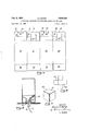
- Figure 1 is a perspective view, partly broken away, of a dispensing container provided according to the invention.
- Figure 2 is a plan view of the structure shown in Figure l. y
- Figure 3 is a cross-section in elevation taken from plane 3-3 of Figure 2, the glass portion of the struc-v ture being shown in phantom for greater clarity.
- Figure 4" is a partial elevation and cross-section taken from the plane 4 4 in Figure 2, the glass portion of the structure being omitted for clarity.
- Figure 5 is a plan view ofk a blank from which the majority of the paperboard portions of the dispensing container may be formed.
- lleC-i States Patent@ Figure 6 is a plan viewof a blank from which a secondary portion of the paperboard structure may be formed.
- Figure 7 is a view of the secondary paperboard structure in its erected position.
- Figure 8 is a view of the dispensing container shown in Figure l inverted and supported on any suitable flat surface or member for use as a dispenser.
- the illustrated dispensing container comprises a glass bottle having a bottom 10, cylindrical sides 11, curved shoulders 12 and a central neck 13 dening a bottle mouth on which is received a removable cap 14.
- the cylindrical sides 11 of the bottle are received against the four upright paperboard side walls 20-23 which are hingedly connected to their adjoining corners as shown, the two free side edges being hinged by means of a tape 24, as shown, or alternatively being connected by a stapled flap' or by other equivalent means.
- the tube comprising the walls 20-23 has a first end wall against which the bottom 10 of the bottle is received.
- This tirst end wall comprises a pair of outer aps 26 which are hinged to the side walls 20 and 22, respectively, and a pair of inner aps 27 which are hinged to the walls 21 and 23. The aps are held closed by the tape 28,*as
- a combined end wall and spacer structure which includes a rst pair of foldable flaps 31 and 33 thatare continuations of theropposite parallel upright side walls 21 and 23 and which are hinged to the ends of the side walls 21 and 23.
- the combined end wall and spacer structure also includes a second pair of foldable aps 30 and 32 that are continuations of the other two upright side walls 20 and 22 of the paperboard tube and that are hinged to the ends thereof and interlock with the flaps 31 and 33.
- Each of the aps 30-33 is of a width corresponding to that one of the upright side walls 20-23 to which it is hinged.
- Each of the rst pair of flaps 31, 33 has a fold line, 35 and 37, respectively, parallel to its hinged edge and spaced therefrom a distance less than half the distance between its hinged edge and the opposite upright side wall to provide an end wall portion and a spacer portion in each ap.
- the ap 31 has an end wall portion between its hinged edge and the end fold line 35 and a spacer portion between the fold line 3S and the edge of the ilap.
- the flap 33 has an end wall portion between its hinged edge and the fold line 37 and a spacer portion between the fold'line 37 and the edge of the ilap.
- Each of the aps 31 and 33 has a pair of parallel slots 41 and 43, respectively, extending from its hinged edge across its end wall portion and partially across its spacer portion. In the assembled condition of the container, each of the slots 41 is aligned with a corresponding one of the slots 43.
- the second pair of aps 30 and 32 have fold lines 34 and 36, respectively, dividing them into end wall portions and spacer portions.
- the end wall portion of the ap 30 extends between its hinged edge and its fold line 34, and the spacer portion of the tlap 30 extends between the fold line 34 and the edge of the flap.
- the end wall portion of the ap 32 extends between its hinged edge and the fold line 36, and the spacer portion of the flap 32 extends between the fold line 36 and the edge ofthe lflap'.
- the end wall portion of the second pair of flaps 30 and 32 are on the outer side of the end wall portion of the tirst pair of aps 31 and 33.
- the spacer portions of the second pair of aps 30 and 32 are positioned in the spaced slots 41 and 43.
- the spacer portions of the second pair of aps 30 and 32 include notches 40 and 42, respectively, which are formed in the flap edges and which are spaced to receive the spacer portions of the rst pair of flaps 31 Vand 33.
- the end wall portions of the flaps 30-33 do not extend over the center of the corresponding end of the container so that there is'provided a central opening 49.
- the spacer portions of the aps 30-33 extend from the end wall portions of these aps to engage against the curved shoulders 12 of the glass bottle and the mouth of the bottle is located on the inner side of the central opening 49.
- the edges of the flaps 30-33 are preferably curved in shallow arcs 50-53 so that the bottle is snugly received against the flaps.
- a paperboard closure 60 is received in the central opening 49.
- the closure 60 comprises a central panel 61 lling the central opening 49 and a plurality of flaps 62 hinged to the central panel 61 and extending inwardly therefrom and being engaged against the curvedV the position shown in Figure l. .
- the lclofsure' 60 ⁇ is removed and the Acap 14 is then removed to be replaced by a dispenser cap 7G provided with a liexible dispensing hose 71"and a 'spring clamp 72 of a conventional ⁇ type for coni Y trolling new.
- the dispensing container is then invertedtothe position shown in Figure 8 and is placed on a liat surface, s uc'h as a shelf ⁇ or anyk bracket provided with an opening through Which the hose 71 can be extended.
- hose 71 The end of the hose 71 is'fastened in an elevated position when the dispenser is not in use.
- vthe dispensing cap 70 and its associated hose are Vremoved and thetbottle is washed out with water and Vrecapped'with the cap 14 for disposal or return.
- Y t the tdispensing container is adapted to'support the electrolytecontaining bottle in dispensing posilion for convenient Yuse ⁇ by the retailer and also at all times the relatively fragile bottle is protected by paperboard and may remain so protected even when it is returned or otherwise disposed of by the user.
- a dispensing container for battery electrolyte and the like comprising a bottle having a body with a bottom, cylindrical sides, curved shoulders and acentral neck defining a bottle mouth, a rectangular paperboard tube having four upright side walls hingedly connectedat their adjoining corners and against which the cylindrical sides of'said bottle are received, said tube having a first end wall against Vwhich Vthe bottom of the bottle is received, a combined end wall and spacer structure at the end of said tube opposite tosaid rst end wall, said combined end wall and vspacerstrueture being formed by a first pair of foldable aps that arecontinuations rof opposite parallel upright side walls of, said tube ajnd that are hinged to the ends of said upright side walls and a second pair of naps that are continuations ofthe other two ⁇ remaining upright sidewalls of said tube and that are hinged to ends thereof and interlocked with the flaps of the Vfirst pair, each Qfsaid flaps being of a width correspondingto that of the upright
- said spacer portions eXtending from said second end wall and being engaged against the curved shoulders of said bottle, the mouth of said bottle ⁇ being ⁇ located ⁇ on theinner side of said central opening, whereby when the dispensing container is inverted the -bottle ⁇ is supported in dispensing position by said spacer portionstand at all times while the dispensing container is in the hands ofthe user the bottlemay be protected by paperboard.
- a dispensing container for battery!electrolyte ⁇ and the like comprising a glass bottle having a body with a bottom, cylindrical sides, curved shoulders and acentral neck defining a bottle mouth, a ⁇ removable cap on said mouth, a rectangular paperboard tubehaving four upright side walls hngedly connected at their adjoining corners and against which the cylindrical sides of said bottle' are receivedsaid tube having a first end Wall against which the bottom ⁇ of the ubottle is received, a
Landscapes
- Engineering & Computer Science (AREA)
- Mechanical Engineering (AREA)
- Cartons (AREA)
Description
Feb. 2, 1960 l. K. BAKER DISPENSING CONTAINER FOR CORROSIVE LIQUIDS OR THE LIKE 2 Sheets-Sheet l Fjled Dec INVENTOR James K-Baker BY KV ATTORNEYS Feb. 2, 1960i J. K, BAKER 2,923,402
DISPENSING CONTAINER FOR CORROSIVE LIQUIDS OR THE LIKE Filed Dec 11, 1957 2 Sheets-Sheet 2 Fi 7 j NVENTOR James KlBaJer' BY /Mwwe/ if gm( ATTORNEYS DISPENSING CONTAINER FOR CORROSIVE LIQUIDS OR THE LIKE 1 James K. Baker, Cleveland, Ohio, assignor to West Virginia Pulp & Paper Company, New York, NX., a corporation of Delaware Application December 11, 1957, Serial No. 702,062
2 Claims. (Cl. 206-46) This invention relates to a dispensing container for battery electrolyte or other corrosive liquids or the like.
It has become widespread practice to ship batteries to retailers, such as service stations and others, in a dry condition. When the battery is sold, electrolyte liquid is added to it by the retailer.
An object of the present invention is to provide a dispensing container for liquids, such as the battery electrolyte, which forms a self-containeddispenser and which maintains the more fragile portions of the container in a condition where they are protected by paperboard at all times while the container is in the hands of the user.
A more particular object of the invention is to provide a combined glass and paperboard container for battery electrolyte and the like which is strong and inexpensive and which is stable and secure in either an upright or inverted position. y
An example of the invention is described below and in the accompanying drawings in which:
Figure 1 is a perspective view, partly broken away, of a dispensing container provided according to the invention.
Figure 2 is a plan view of the structure shown in Figure l. y
Figure 3 is a cross-section in elevation taken from plane 3-3 of Figure 2, the glass portion of the struc-v ture being shown in phantom for greater clarity.
Figure 4"is a partial elevation and cross-section taken from the plane 4 4 in Figure 2, the glass portion of the structure being omitted for clarity.
Figure 5 is a plan view ofk a blank from which the majority of the paperboard portions of the dispensing container may be formed.
lleC-i States Patent@ Figure 6 is a plan viewof a blank from which a secondary portion of the paperboard structure may be formed.
Figure 7 is a view of the secondary paperboard structure in its erected position.
Figure 8 is a view of the dispensing container shown in Figure l inverted and supported on any suitable flat surface or member for use as a dispenser.
The illustrated dispensing container comprises a glass bottle having a bottom 10, cylindrical sides 11, curved shoulders 12 and a central neck 13 dening a bottle mouth on which is received a removable cap 14. The cylindrical sides 11 of the bottle are received against the four upright paperboard side walls 20-23 which are hingedly connected to their adjoining corners as shown, the two free side edges being hinged by means of a tape 24, as shown, or alternatively being connected by a stapled flap' or by other equivalent means. The tube comprising the walls 20-23 has a first end wall against which the bottom 10 of the bottle is received. This tirst end wall comprises a pair of outer aps 26 which are hinged to the side walls 20 and 22, respectively, and a pair of inner aps 27 which are hinged to the walls 21 and 23. The aps are held closed by the tape 28,*as
ice A 2 shown. Other equivalent end wall means may be provided.
At the opposite end from the rst end wall of the tube which comprises the walls 20-23, there is provided a combined end wall and spacer structure which includes a rst pair of foldable flaps 31 and 33 thatare continuations of theropposite parallel upright side walls 21 and 23 and which are hinged to the ends of the side walls 21 and 23. The combined end wall and spacer structure also includes a second pair of foldable aps 30 and 32 that are continuations of the other two upright side walls 20 and 22 of the paperboard tube and that are hinged to the ends thereof and interlock with the flaps 31 and 33. Each of the aps 30-33 is of a width corresponding to that one of the upright side walls 20-23 to which it is hinged.
Each of the rst pair of flaps 31, 33 has a fold line, 35 and 37, respectively, parallel to its hinged edge and spaced therefrom a distance less than half the distance between its hinged edge and the opposite upright side wall to provide an end wall portion and a spacer portion in each ap. Thus the ap 31 has an end wall portion between its hinged edge and the end fold line 35 and a spacer portion between the fold line 3S and the edge of the ilap. The flap 33 has an end wall portion between its hinged edge and the fold line 37 and a spacer portion between the fold'line 37 and the edge of the ilap.
Each of the aps 31 and 33 has a pair of parallel slots 41 and 43, respectively, extending from its hinged edge across its end wall portion and partially across its spacer portion. In the assembled condition of the container, each of the slots 41 is aligned with a corresponding one of the slots 43.
The second pair of aps 30 and 32 have fold lines 34 and 36, respectively, dividing them into end wall portions and spacer portions. The end wall portion of the ap 30 extends between its hinged edge and its fold line 34, and the spacer portion of the tlap 30 extends between the fold line 34 and the edge of the flap. The end wall portion of the ap 32 extends between its hinged edge and the fold line 36, and the spacer portion of the flap 32 extends between the fold line 36 and the edge ofthe lflap'.
The end wall portion of the second pair of flaps 30 and 32 are on the outer side of the end wall portion of the tirst pair of aps 31 and 33. The spacer portions of the second pair of aps 30 and 32 are positioned in the spaced slots 41 and 43. The spacer portions of the second pair of aps 30 and 32 include notches 40 and 42, respectively, which are formed in the flap edges and which are spaced to receive the spacer portions of the rst pair of flaps 31 Vand 33.
lt will be seen that the end wall portions of the flaps 30-33 do not extend over the center of the corresponding end of the container so that there is'provided a central opening 49. The spacer portions of the aps 30-33 extend from the end wall portions of these aps to engage against the curved shoulders 12 of the glass bottle and the mouth of the bottle is located on the inner side of the central opening 49. The edges of the flaps 30-33 are preferably curved in shallow arcs 50-53 so that the bottle is snugly received against the flaps.
A paperboard closure 60 is received in the central opening 49. The closure 60 comprises a central panel 61 lling the central opening 49 and a plurality of flaps 62 hinged to the central panel 61 and extending inwardly therefrom and being engaged against the curvedV the position shown in Figure l. .When it is to be used l by the` retailer or other` end user, the lclofsure' 60 `is removed and the Acap 14 is then removed to be replaced by a dispenser cap 7G provided with a liexible dispensing hose 71"and a 'spring clamp 72 of a conventional `type for coni Y trolling new. The dispensing container is then invertedtothe position shown in Figure 8 and is placed on a liat surface, s uc'h as a shelf `or anyk bracket provided with an opening through Which the hose 71 can be extended.
The end of the hose 71 is'fastened in an elevated position when the dispenser is not in use. When the contents of the bottle are exhausted, vthe dispensing cap 70 and its associated hose are Vremoved and thetbottle is washed out with water and Vrecapped'with the cap 14 for disposal or return. Thus, it will be seen that'the tdispensing container is adapted to'support the electrolytecontaining bottle in dispensing posilion for convenient Yuse `by the retailer and also at all times the relatively fragile bottle is protected by paperboard and may remain so protected even when it is returned or otherwise disposed of by the user. Y t
t The invention is not necessarily limited in scope to all thedetals ofthe above disclosure. For example, one
`aspect of the .invention contemplates in certain' instances the use of bottles made from polyethylene and other similar materials rather than glass, although the contribution of the invention is perhaps .most signicant in connection with the use of glass bottles.
What is claimed is: Y
l. A dispensing container for battery electrolyte and the like comprising a bottle having a body with a bottom, cylindrical sides, curved shoulders and acentral neck defining a bottle mouth, a rectangular paperboard tube having four upright side walls hingedly connectedat their adjoining corners and against which the cylindrical sides of'said bottle are received, said tube having a first end wall against Vwhich Vthe bottom of the bottle is received, a combined end wall and spacer structure at the end of said tube opposite tosaid rst end wall, said combined end wall and vspacerstrueture being formed by a first pair of foldable aps that arecontinuations rof opposite parallel upright side walls of, said tube ajnd that are hinged to the ends of said upright side walls and a second pair of naps that are continuations ofthe other two `remaining upright sidewalls of said tube and that are hinged to ends thereof and interlocked with the flaps of the Vfirst pair, each Qfsaid flaps being of a width correspondingto that of the upright side wall to which it is hinged, each flap of said first pair having a fold line` parallel to its hinged edge and spaced therefrom a distance less than one half .the distance .between its hinged edge and the opposite having end wall portions that are on the vouter side of,
the endwall 4portions of the aps of said'tirst pair and spacer portions hinged to Vtheir bottom portions, positioned in the spaced slots of the flaps of said first pair and having notches in their edges spaced to receive the spacer portions of the naps of therst pair, said end wall portions providing the tube' witha second end wall having 'a central rectangular opening? said spacer portions eXtending from said second end wall and being engaged against the curved shoulders of said bottle, the mouth of said bottle` being `located `on theinner side of said central opening, whereby when the dispensing container is inverted the -bottle `is supported in dispensing position by said spacer portionstand at all times while the dispensing container is in the hands ofthe user the bottlemay be protected by paperboard. j
2. A dispensing container for battery!electrolyte` and the like comprising a glass bottle having a body with a bottom, cylindrical sides, curved shoulders and acentral neck defining a bottle mouth, a `removable cap on said mouth, a rectangular paperboard tubehaving four upright side walls hngedly connected at their adjoining corners and against which the cylindrical sides of said bottle' are receivedsaid tube having a first end Wall against which the bottom `of the ubottle is received, a
combined e`nd wall and, spacer structure at the endlof said tube opposite 'to said iirst end wall, said combined end wall and spacer structure being formed by a irstpair `hinged edgeA and spaced therefrom a distance less than one half the distance between its hinged edge and the opposite upright side wall to provide an end `wall portion between said 4fold line and said hinged edgeand a spacer portion hinged tothe end wall portion at saidfold line, t p each flap of said first pair having twoparallel slots extending from vits hinged edge across its end wall portion and partially across its 4spacer portion,I the slots o'f the two flaps of said"first pair `being aligned, the flaps bf Vsaid second pair having` end wall portions that] are on the Vouter side ofthe end wall portions of the flaps oftsaid nrst pair and spacer portions hinged `to their bottom portions, positioned'in the spaced slots of the naps of said Viirst pair vand having notches in their edges spaced Vto receive the spacer portionsof the flaps of the l'irstlpair, said end wall portions'providing the tube witha` second end wall having a central rectangular opening, said spacer por-` tions eXtending from said secondend walland being en `gaged against the curved shoulders of said bo'ttle, the mouth of said bottle being located on the innerside of` said central opening, a paperboard 'closure received in said central opening, said closure comprising :a central` panel filling said central opening and aplurality of ilaps hinged to said central panel and extending inwardly therefrom and being engaged against the curved shoulders` of said bottle,
References Cited in the iile of this patent UNITED STATES PATENTS
Priority Applications (1)
| Application Number | Priority Date | Filing Date | Title |
|---|---|---|---|
| US702062A US2923402A (en) | 1957-12-11 | 1957-12-11 | Dispensing container for corrosive liquids or the like |
Applications Claiming Priority (1)
| Application Number | Priority Date | Filing Date | Title |
|---|---|---|---|
| US702062A US2923402A (en) | 1957-12-11 | 1957-12-11 | Dispensing container for corrosive liquids or the like |
Publications (1)
| Publication Number | Publication Date |
|---|---|
| US2923402A true US2923402A (en) | 1960-02-02 |
Family
ID=24819716
Family Applications (1)
| Application Number | Title | Priority Date | Filing Date |
|---|---|---|---|
| US702062A Expired - Lifetime US2923402A (en) | 1957-12-11 | 1957-12-11 | Dispensing container for corrosive liquids or the like |
Country Status (1)
| Country | Link |
|---|---|
| US (1) | US2923402A (en) |
Cited By (6)
| Publication number | Priority date | Publication date | Assignee | Title |
|---|---|---|---|---|
| US3819036A (en) * | 1972-09-01 | 1974-06-25 | Owens Illinois Inc | Safety pouring package for dangerous chemicals |
| FR2628392A1 (en) * | 1988-03-11 | 1989-09-15 | Arques Verrerie Cristallerie | Presentation pack unit - has rounded square top with four arms extending to two pairs of interlocking slotted base tabs |
| US5213215A (en) * | 1991-03-22 | 1993-05-25 | Societe Dite Les Isolants Du Sudouest | Advanced shock-proof packing fragile objects, such as bottles |
| US5553709A (en) * | 1994-12-21 | 1996-09-10 | Kinetics Container Corporation | Container assembly for plastic bottles and the like |
| EP1211192A3 (en) * | 2000-09-08 | 2002-12-11 | Arthur G. Rutledge | Package and method of packaging for dangerous goods |
| FR2851234A1 (en) * | 2003-02-13 | 2004-08-20 | Smurfit Socar Sa | Bottle package has internal flaps at the necks of the bottles and which can be bent to form reinforcement elements |
Citations (4)
| Publication number | Priority date | Publication date | Assignee | Title |
|---|---|---|---|---|
| US2653708A (en) * | 1949-04-26 | 1953-09-29 | Owens Illinois Glass Co | Carton and packing cell |
| US2693308A (en) * | 1950-02-11 | 1954-11-02 | Hinde & Daucn Paper Company | Multicompartment shipping carton |
| US2811295A (en) * | 1954-06-01 | 1957-10-29 | River Raisin Paper Company | Carton for supporting a container |
| US2868428A (en) * | 1955-06-01 | 1959-01-13 | Continental Can Co | Bottle shipping container with internal yieldable supports |
-
1957
- 1957-12-11 US US702062A patent/US2923402A/en not_active Expired - Lifetime
Patent Citations (4)
| Publication number | Priority date | Publication date | Assignee | Title |
|---|---|---|---|---|
| US2653708A (en) * | 1949-04-26 | 1953-09-29 | Owens Illinois Glass Co | Carton and packing cell |
| US2693308A (en) * | 1950-02-11 | 1954-11-02 | Hinde & Daucn Paper Company | Multicompartment shipping carton |
| US2811295A (en) * | 1954-06-01 | 1957-10-29 | River Raisin Paper Company | Carton for supporting a container |
| US2868428A (en) * | 1955-06-01 | 1959-01-13 | Continental Can Co | Bottle shipping container with internal yieldable supports |
Cited By (6)
| Publication number | Priority date | Publication date | Assignee | Title |
|---|---|---|---|---|
| US3819036A (en) * | 1972-09-01 | 1974-06-25 | Owens Illinois Inc | Safety pouring package for dangerous chemicals |
| FR2628392A1 (en) * | 1988-03-11 | 1989-09-15 | Arques Verrerie Cristallerie | Presentation pack unit - has rounded square top with four arms extending to two pairs of interlocking slotted base tabs |
| US5213215A (en) * | 1991-03-22 | 1993-05-25 | Societe Dite Les Isolants Du Sudouest | Advanced shock-proof packing fragile objects, such as bottles |
| US5553709A (en) * | 1994-12-21 | 1996-09-10 | Kinetics Container Corporation | Container assembly for plastic bottles and the like |
| EP1211192A3 (en) * | 2000-09-08 | 2002-12-11 | Arthur G. Rutledge | Package and method of packaging for dangerous goods |
| FR2851234A1 (en) * | 2003-02-13 | 2004-08-20 | Smurfit Socar Sa | Bottle package has internal flaps at the necks of the bottles and which can be bent to form reinforcement elements |
Similar Documents
| Publication | Publication Date | Title |
|---|---|---|
| US2979222A (en) | Case for cartons | |
| US3123213A (en) | Article carrier | |
| US2046484A (en) | Duplex container | |
| US3687282A (en) | Container package | |
| US11427376B2 (en) | Packaging insert for an advent calendar and/or beer packaging container | |
| US3828926A (en) | Multi-unit package with curved contour | |
| US3119543A (en) | Neck securement for containers | |
| US4382505A (en) | Wrap around carrier for returnable bottles | |
| US3066843A (en) | Shipping and/or dispensing container | |
| US2823063A (en) | Carrier cartons | |
| GB2038764A (en) | Bottle carrier | |
| US3370776A (en) | Dispenser package | |
| US2854181A (en) | Carton | |
| US2448795A (en) | Divisible carton | |
| US3498523A (en) | Container for carrying bottles or the like | |
| US3784002A (en) | Multiple container carrier and individual container lid arrangement | |
| US2923402A (en) | Dispensing container for corrosive liquids or the like | |
| US2981405A (en) | Shipping and/or storing container | |
| US3114474A (en) | Dispenser carton | |
| US1970970A (en) | Hermetically sealed container | |
| US3669343A (en) | Holder for tetrahedron packages | |
| US3049282A (en) | Can carton with reinforced corners | |
| US3819036A (en) | Safety pouring package for dangerous chemicals | |
| US3926307A (en) | Bottle carrier | |
| US3927789A (en) | Bottle packing |