US2920217A - Arbitrary waveform generator - Google Patents
Arbitrary waveform generator Download PDFInfo
- Publication number
- US2920217A US2920217A US659188A US65918857A US2920217A US 2920217 A US2920217 A US 2920217A US 659188 A US659188 A US 659188A US 65918857 A US65918857 A US 65918857A US 2920217 A US2920217 A US 2920217A
- Authority
- US
- United States
- Prior art keywords
- voltage
- core
- units
- output
- current
- Prior art date
- Legal status (The legal status is an assumption and is not a legal conclusion. Google has not performed a legal analysis and makes no representation as to the accuracy of the status listed.)
- Expired - Lifetime
Links
Images


Classifications
-
- G—PHYSICS
- G06—COMPUTING; CALCULATING OR COUNTING
- G06G—ANALOGUE COMPUTERS
- G06G7/00—Devices in which the computing operation is performed by varying electric or magnetic quantities
- G06G7/12—Arrangements for performing computing operations, e.g. operational amplifiers
- G06G7/26—Arbitrary function generators
- G06G7/28—Arbitrary function generators for synthesising functions by piecewise approximation
-
- H—ELECTRICITY
- H03—ELECTRONIC CIRCUITRY
- H03M—CODING; DECODING; CODE CONVERSION IN GENERAL
- H03M1/00—Analogue/digital conversion; Digital/analogue conversion
- H03M1/66—Digital/analogue converters
- H03M1/74—Simultaneous conversion
- H03M1/742—Simultaneous conversion using current sources as quantisation value generators
Definitions
- This invention relates in general to arbitrary waveform generatorsand in particular to such generators employing magnetic core elements having a substantially rect-angula-r hysteresis loop characteristic.
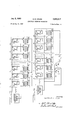
- Fig. 1 is a schematic showing of a simplified embodia ment of the present invention.
- Fig. 2 is a graphical showing of possible output voltages for the embodiments of Figs. 1 and 3.
- Fig. 3 is a schematic showing of a preferred embodi-.
- Fig.4 is a schematic showing of another preferred em
- the device employs a determinatenumber of positive voltage sources and an equal number of; negative voltage sources. which are connected; in. series opposition to produce a Zero difference voltage when allthevoltage sources are applied across the outload.
- Means are provided for efiectivelyremoving selected number of positive or negative voltage spuwes; during a prescribed; time interval such that a (lit!ereucevoltage equal in magnitudeto the algebraicl atented Jan. 5, 1960 sum of the removed voltage sources and of opposite polarity with respect thereto appears across the output load impedance.
- Magnetic switching circuitry is employed to control the operation of the device and a single alternating voltage source is employed to provide a. plurality of voltage sources in the preferred embodiments of the device.
- Fig. 1 six voltage sources are shown serially connected in opposition across the output terminals 7 and 8 with three of each polarity. It is understood that while, for purpose of simplicity, only six voltage sources are shown, more than six voltage sources may be utilized if desired.
- the six voltage sources E E E E E and E will be com sidered equal in value and of the polarity indicated so that with all of the on-ofi bypass switches S S S S and S in their open state, the voltage sources sum to zero and no net output voltage 6 appears across the output terminals 7 and 8.
- the solid line curve represents a typical output waveform obtainable with the embodiment of Fig. 2 by the selected closure of various bypass switches in time sequence.
- FIG. 3 A more complex embodiment of the present invention is shown in Fig. 3.
- This embodiment utilizes an alternating voltage source and a plurality of halfcycle response magnetic amplifiers to produce a stepwise output" voltage waveform rather than a plurality of separate DC. voltage sources with on-off bypass switches.
- the alternating voltage source 11 may be a square wave generator and it has been found that this type of supply voltage is especially adaptable to the present invention.
- it might be preferable to employ other input waveforms such as sinusoidal or triangular.
- Each of the half cycle response magnetic amplifier un ts 2, 3, n :7 pera indep n en ly ofthe others and is, enclosed; by dashed lines in the drawing.
- Each unit comprises a primary winding 21 and a secondary winding. lgwound on a magnetic core ofa material having a substantially rectangular hysteresis loop characteristic with the primary winding connected across the voltage source 11 via a nonreciprocal imp a cirwiflv mpri ng. a w re stance .3 and a unidirectional element24 in series, shuntedby a relatively high variable resistance 25.
- the output ofthe type oftransformer above referred to is dependent upon the saturation condition of the transformer core. That is, a voltage output is obtained only during the period when the flux level of the core is changing. Once a flux saturation level is reached, the voltage output effectively drops to zero.
- r Q J 1 In general operational analysis of the half-cycle mag-' netic amplifier circuitry, the firing angle of a core during the gating half-cycle of such units is uniquely determined during the preceding half-cycle, which is known as the reset half-cycle, by the resetting voltage applied; In the embodiment of Fig. 3, the reset half-cycle is that during which the unidirectional elements block current flow through themselves.
- the voltage appearing across the primary winding 21 and the secondary winding 22 during the reset half-t cycle is established by the magnitude of the output of voltage source 11 minus the voltage drop across there'- sistance 25.
- the'amount of reset of each core may be individually controlled by varying its respective resistance 25.
- the gating half-cycle begins and the unidirectional element in series with the primary winding 21 conducts and sub-' stantially the full output of'voltage source 11 is applied across the primary winding 21 as the drop across the resistance23is negligible While the core is in the nonsaturated condition.
- the secondary windings on each core are connected in series across the output terminals and thus the voltages appearing across the secondary windings add. Considering an equal turns ratio for the transformers, and an equal number of secondary windings of each polarity, it will be appreciated that the voltages will sum to zero across the output terminals 7 and 8 when the polarity of the voltage source 11 reverses.
- the number of voltage levels or points which may be included in a specified waveform is controlled by the number of voltage steps of each polarity available.
- an embodiment employing only six magnetic amplifier units such as shown in Figs. 1 and 3 could not produce a waveform which started at zero, went to a point on line a, then to a point on line g and return to line a since this would require nine positive and six negative steps and only three of each are available ultilizing the embodiments of Figs. 1 and 3.
- An equivalent waveform could be synthesized, however, by going to line 0, then line e and re turn. This procedure is possible with the embodiments of Figs. 1 and 3 since it requires only three positive and two negative steps. 7
- polarity sensitive switch has been incorporated to interrupt the output load circuitry during the reset half-cycle when the primary windings are most sensitive to load current in the secondary windings. It will be seen that this sensitivity is primarily due to the relatively high impedance 25 in series with each core during the reset halfcycle. Any current flow in the secondary windings resulting from unbalanced voltages in the output circuitry not effect any core. Thus the voltage appearing across the transformer'windings is solely dependent upon the respective primary current and the respective turns ratio involved.
- an A.C. or two way junction transistor switch is employed to interrupt the output circuitry during the reset half-cycle. This type of switch is well known in the art and is fully described in the article by R. L. Bright which appeared in A.I.E.E.
- the switch impedance drops to a few ohms and places no limit, effectively upon load current flow.
- the common emitter electrodes become negative with respect to the common base electrodes in the two transistors and the transistors block.
- the resistor 33 serves to set the base current and resistor 34 serves to limit the back voltage applied to the base-emitter junction when the switch is in the open or blocking state.
- a two way transistor switch has been employed to allow for secondary circuit flow in either direction due to the possibility of' an unbalanced voltage condition of either polarity.
- a transistorized switching means be employed, and any suitable, polarity sensitive on-oiI switching means may be readily substi-.
- transfOrm r 4.0 is merely to provide an additional alternating voltage source operating in synchronization with the voltage, source 11 and that a separate voltage source synchronous, with the voltage source 11 may be readily substituted in place thereof.
- a nonlinear impedance means is employed for this purpose.
- This nonlinear impedance means comprises the parallel connected potentiometers 51. and 52 plus the unidirectional element 53 by which the otentiometers 51 and 52 are connected across the secondary winding 22.
- th dua potentiometerarrangement permits a varia ion of he. masni udeand p y of h p- It will be seen that a single potentiometer would serve equally as well as the dual potentiometer arrangement, insofar as maintaining the transformed primary voltage across the secondary winding it shunts. The substitution of a single potentiometer would permit a Variation of magnitude, but not polarity, of each step.
- a twelve magnetic amplifier unit embodiment in accordance with the embodiment of Fig. 5, has been used successfully as an input wave-form generator with the transcendental function analogue computer described and claimed in the copending application of R. L. Van Allen, Serial No. 619,651, now Patent No. 2,808,990 which is entitled Polarity Responsive Voltage Computing Means.
- a magnetic waveform generator comprising a plurality of half-cycle response magnetic amplifier units, each of said units-including a primary winding and a secondary winding Wound on a core of a material having a substantially rectangular hysteresis loop characteristic, first means for bringing the core in each of said units from its respective flux saturation level to a respective predetermined flux level, said first means including means for varying said predetermined flux level in each of said units independently of the remainder of said units; means for concurrently returning each of the cores in said units to their respective original saturation levels at a common flux changing rate following the operation of said first means; a pair of output terminals; and means interconnecting said secondary windings in series across said output terminals.
- a magnetic waveform generator comprising a plurality, of half-cycle response magnetic amplifier units, each of said units including a primary winding and a secondary winding wound on a core of a material having a substantially rectangular hysteresis loop characteristic, first means for bringing the core in each of said units from its respective flux saturation level to a respective predetermined flux level, said first means including means for varying said predetermined flux level in each of said units independently of the remainder of said units; means for concurrently returning each of the cores in said units to their respective original saturation levels at a common flux changing rate following the operation of saidfirst means; a pair of output terminals; means interconnecting said secondary windings in series across said output terminals and switching means operable to interrupt said serial connection of secondary windings during the operation of said first means.
- a magnetic waveform generator comprising a plurality of half-cycle response magnetic amplifier units, each of said units including a primary winding and a secondary winding wound on a core of a material having a substantially rectangular hysteresis loop characteristic, first means for bringing the core in each of said units from its respective flux saturation level to a respective prede termined flux level, said first means including means for varying said predetermined flux level in each of said units independently of the remainder of said units; means for concurrently returning each of the cores in said units to their respective original saturation levels at a common flux changing rate following the operation of said first means; said means for returning said cores to their respective saturation levels including current limiting means for limiting current flow in each of said primary windings after the respective saturation level is reached; a pair of substantially rectangular hysteresis loop characteristic, first means for bringing the core in each of said' units from its respective flux saturation level to a respective predetermined flux level, said first means including means for varying said predetermined flux level in each of said units independently ofthe remainder
- a magnetic-waveform generator comprising a plurality of half-cycle response magneticamplifier units, each of said units including a primary winding and a secondary ,winding wound on a core of a material'having-a substantially rectangular hysteresis loop characteristic; and alternating voltage source; each of said primarywindings in said plurality being connected in parallel across said voltage source via respective nonreciprocal impedance, means comprising unidirectional means and a low impedance connected in series and a relatively high impedance which shunts said unidirectional-means and said low impedance; a pair of output terminals; and means interconnecting said secondary windings in series across said pair of output terminals such that at least one of, said secondary windings is of opposing polarity with respect to the remainder of said secondary windings.
- a magnetic waveform generator comprising a, plurality of half-cycle response magnetic amplifier units, each of said units including a primary winding and a secondary winding wound on a core of a material having a substantially rectangular hysteresis loop characteristic; an alternating voltage source; each of said primarywindings in said plurality being connected in parallel across said voltage source via respective nonreciprocal impedance means comprising unidirectional means and a current limiting means connected in series and a relatively high impedance which shunts said unidirectional means and said current limiting means; said current limiting means being operable to limit current flow in each of said primary windings when the respective core reaches saturation; a pair of output terminals; and means interconnecting said secondary windings in series across said pair of output terminals such that atleast one of said secondary windings is of opposing polarity with respect to the remainder of said secondary windings.
- a magnetic waveform generator comprising a plurality of half-cycle response magnetic amplifier units, each of said units including a primary winding and a secondary winding wound on a core of a material having a substantially rectangular hysteresis loop characteristic;
- each of said primary windings in said plurality being connected in parallel across said voltage source via respective nonreciprocal.
- 'im pedance means comprising, unidirectional means anda nonlinear current limiting meansconnected in series and a relatively high impedance which shunts said unidirectional means and said nonlinear current limiting means; said nonlinear current limiting means being operable to limit current flow in each of said primary windings when the respective core reaches saturation; a pair of output terminals; and means interconnecting said sec: ondary windings in series across said pair of output terminals such that at least one of said secondary windings is of opposing polarity with respect to the remainder of said secondary windings.
- a magnetic'waveform generator comprising an even plurality of half-cycle response magnetic amplifier units, each of said .units including a primary winding and a secondary winding wound on' a core of a material having a substantially rectangular hysteresis loop characteristic; an alternating voltage source; each of said primary windings in said plurality being connected in parallel across said voltage source via respective nonreciprocal impedance means comprising unidirectionalmeans and a low impedance connected'in series and a'relatively high impedance which shunts said unidirectional means and said low impedance; a pair of output terminals; and means interconnecting said secondary windingsin series across said pair of output terminals such that one half of said secondary windings are are of opposing polarity with respect to the remainder of said secondary windings.
- a magnetic waveform generator comprising a plurality of half-cycle response magnetic amplifier units, each of said units including a primary winding and a secondary winding wound on a core of a material having a substantially rectangular hysteresis loop characteristic; an alternating voltage source; each of said primary windings in said plurality being connected in parallel across said voltage source via respective nonreciprocal impedance means comprising unidirectional means and current biased diode current limiting means connected in' series and a relatively high impedance which shunts said unidirectional means and said current limiting means; said current limiting means being operabletto limit current flow in each of said primary windings when the respective core reaches saturation; a pairof output terminals; means interconnecting said'secondary winding s in series across said output terminals; voltage limiting means connected in parallel with each of said secondary windings; and switching means operable to interrupt said serial connection of said secondary windings during the period said unidirectional means blockcurrent flow.
Description
Jan. 5, 1960 c. B. HOUSE 2,920,217
ARBITRARY. WAVEFORM GENERATOR Filed May 14, 1957 3 Sheets-Sheet 1 :Elfil E E E 4 5 6 S s s s s s VO'LTAG E INVENTOR CLARENCE B. HOUSE BY W%% W ATTORNEYS 3 Sheets-Sheet 2 INVENTOR CLARENCE B. HOUSE C. B. HOUSE ARBITRARY WAVEFORML GENERATOR Jan. 5, 1960 Filed May 14, 1957 BY 7% "if;
\ ATTORNEY Jan. 5, 1960 c. B. HOUSE 2,920,217
' ARBITRARY WAVEFORM GENERATOR Filed May 14, 1957 3 Sheets-Sheet 3 3| MZQDQrmQQQQL m Fo 252 H 1 INVENTOR CLARENCE B. HOUSE 1 ATTORNEY 5 United States Patent ARBITRARY WAVEFORM GENERATOR Clarence B. House, Arlington, Va.
Application May 14, 1957, Serial No. 659,188 9 Claims. 01. 307106) (Granted under Title 35, US. Code (1952), see. 2 66) The invention described herein may be manufactured and, used by or for the Government of the United States of America for governmental purposes without the payment of any royalties thereon ortherefor.
This invention relates in general to arbitrary waveform generatorsand in particular to such generators employing magnetic core elements having a substantially rect-angula-r hysteresis loop characteristic.
Function 0r arbitrary Waveform generators of various different kinds are commonly used in a wide variety of electronic applications. They are particularly useful in the electronic computer field where the waveform of the input voltage is usually of considerable significance v In general, the requirements of an ideal function genera-tor for use in computer applications include simple alignment, reliability, repeatability and the ability to produce steps as part of the output function. In addition, it is frequently desirable that the generator be a completely static device to correspond with cooperating devices.
Therefore:
It is an object of this invention to provide an improved arbitrary waveform generator capable of producing a substantially unlimited number of diile-rent waveforms.
It is another object of this invention to provide an improved arbitrary waveform generator employing static components.
It is still another object of this invention to-provide an improved arbitrary waveform generator which is relatively insenitiwe to-load impedance variations.
Other objects of the invention will become apparent upon a more comprehensive understanding of the in vention for which reference is had to the following detailed description of the invention and the accompanying drawings, in which:
Fig. 1 is a schematic showing of a simplified embodia ment of the present invention.
Fig. 2 is a graphical showing of possible output voltages for the embodiments of Figs. 1 and 3.
Fig. 3 is a schematic showing of a preferred embodi-.
ment of the present invention.
Fig.4 is a schematic showing of another preferred em;
Iiitude. In its basic form, the device employs a determinatenumber of positive voltage sources and an equal number of; negative voltage sources. which are connected; in. series opposition to produce a Zero difference voltage when allthevoltage sources are applied across the outload. Means are provided for efiectivelyremoving selected number of positive or negative voltage spuwes; during a prescribed; time interval such that a (lit!ereucevoltage equal in magnitudeto the algebraicl atented Jan. 5, 1960 sum of the removed voltage sources and of opposite polarity with respect thereto appears across the output load impedance. Magnetic switching circuitry is employed to control the operation of the device and a single alternating voltage source is employed to provide a. plurality of voltage sources in the preferred embodiments of the device.
Referring now to the drawings in detail:
In Fig. 1, six voltage sources are shown serially connected in opposition across the output terminals 7 and 8 with three of each polarity. It is understood that while, for purpose of simplicity, only six voltage sources are shown, more than six voltage sources may be utilized if desired. For purposes of this explanation, the six voltage sources E E E E E and E will be com sidered equal in value and of the polarity indicated so that with all of the on-ofi bypass switches S S S S S and S in their open state, the voltage sources sum to zero and no net output voltage 6 appears across the output terminals 7 and 8.
' It will be seen that by closing any selected number of switches, a corresponding number of voltage sources will be shorted out and a voltage equal in magnitude to the summation of the removed voltage sources will appear across the output terminals 7 and 8 This operational state will remain, of course, until the switching arrangement is revised.
The stepwise effect of closing the switches in the embodiment of Fig. 1 will be more fully appreciated upon consideration of'Fig. 2 which shows e the output voltage appearing across the terminals 7 and 8, plotted against time. In Fig. 2, each of the dotted lines, a, b, c, d, e, f, and g, represents a voltage level which may appear across the output terminals on closing various combinations of switches in the embodiment of Fig. 1.
The solid line curve represents a typical output waveform obtainable with the embodiment of Fig. 2 by the selected closure of various bypass switches in time sequence.
A more complex embodiment of the present invention is shown in Fig. 3. This embodiment utilizes an alternating voltage source and a plurality of halfcycle response magnetic amplifiers to produce a stepwise output" voltage waveform rather than a plurality of separate DC. voltage sources with on-off bypass switches. As in Fig. 1, for purposes of simplicity, only six half-cycle magnetic amplifiers are shown, both is understood that; a greater number may be utilized, if desired. As indicated in the drawing, the alternating voltage source 11 may be a square wave generator and it has been found that this type of supply voltage is especially adaptable to the present invention. Of course, for special applications it might be preferable to employ other input waveforms such as sinusoidal or triangular. However, since these other waveforms would tend to restrictthe flexibil ity of the output waveforms, only a square wave input waveform will be considered herein. It will be appreci. ated that the basic principles discussed herein also will apply if other waveforms are employed.
Each of the half cycle response magnetic amplifier un ts 2, 3, n :7 pera indep n en ly ofthe others and is, enclosed; by dashed lines in the drawing. Each unit comprises a primary winding 21 and a secondary winding. lgwound on a magnetic core ofa material having a substantially rectangular hysteresis loop characteristic with the primary winding connected across the voltage source 11 via a nonreciprocal imp a cirwiflv mpri ng. a w re stance .3 and a unidirectional element24 in series, shuntedby a relatively high variable resistance 25.
As is well knownto those skilled in the art, the output ofthe type oftransformer above referred to is dependent upon the saturation condition of the transformer core. That is, a voltage output is obtained only during the period when the flux level of the core is changing. Once a flux saturation level is reached, the voltage output effectively drops to zero. r Q J 1 In general operational analysis of the half-cycle mag-' netic amplifier circuitry, the firing angle of a core during the gating half-cycle of such units is uniquely determined during the preceding half-cycle, which is known as the reset half-cycle, by the resetting voltage applied; In the embodiment of Fig. 3, the reset half-cycle is that during which the unidirectional elements block current flow through themselves. Considering the magnetic amplifiers separately, the voltage appearing across the primary winding 21 and the secondary winding 22 during the reset half-t cycle is established by the magnitude of the output of voltage source 11 minus the voltage drop across there'- sistance 25. Thus it will be seen that the'amount of reset of each core may be individually controlled by varying its respective resistance 25.
When the polarity of voltage source 11 reverses, the gating half-cycle begins and the unidirectional element in series with the primary winding 21 conducts and sub-' stantially the full output of'voltage source 11 is applied across the primary winding 21 as the drop across the resistance23is negligible While the core is in the nonsaturated condition. As shown in the drawing, the secondary windings on each core are connected in series across the output terminals and thus the voltages appearing across the secondary windings add. Considering an equal turns ratio for the transformers, and an equal number of secondary windings of each polarity, it will be appreciated that the voltages will sum to zero across the output terminals 7 and 8 when the polarity of the voltage source 11 reverses.
As soon as a core saturates, its transformed voltage dis appears and a voltage equal inmagnitude and opposite in polarity to thatwhich disappeared appears across the output terminals 7 and 8. If the next core to saturate has the same polarity as the preceding one, the voltage appearing across the output will increase. On the other hand, if the next core to saturate does not have the same polarity as the preceding one, the voltage appearing across the output terminals 7 and 8 will decrease and reverse the slope of the output waveform. It will be' seen that this synthesizing action vcontinues either until the gating half-cycle is ended or until all cores have saturated, whichever occurs first. a I
g It will be appreciated that the number of voltage levels or points which may be included in a specified waveform is controlled by the number of voltage steps of each polarity available. For example, considering Fig. 2 again, an embodiment employing only six magnetic amplifier units such as shown in Figs. 1 and 3 could not produce a waveform which started at zero, went to a point on line a, then to a point on line g and return to line a since this would require nine positive and six negative steps and only three of each are available ultilizing the embodiments of Figs. 1 and 3. An equivalent waveform could be synthesized, however, by going to line 0, then line e and re turn. This procedure is possible with the embodiments of Figs. 1 and 3 since it requires only three positive and two negative steps. 7
It will be seen that for a given number of magnetic amplifier units, it might be preferred in order to fit complex curves, for example, to employ different voltage values for some of the steps shown in the graph of Fig. 2. A means for accomplishing this effect will be dealt with in the discussion of Fig. 5.
While the theoretical waveform shown in Fig. 2 depicts an abrupt change from the one voltage level to another, it will be appreciated that in the practical case, the change willnot occur instantaneously but will occur over ashort mead-9f t me du o, the s is r s u pe, 9 th saturating cores which in turn gives a slope to the theochange the flux level of the transformer core material.
Where a greater amount of output load current is re quired, and the embodiment of Fig. 3 would not be satisfactory, the embodiment of Fig. 4 may be advantageously substitutedtherefor. In the embodimentof Fig. 4 a
polarity sensitive switch has been incorporated to interrupt the output load circuitry during the reset half-cycle when the primary windings are most sensitive to load current in the secondary windings. It will be seen that this sensitivity is primarily due to the relatively high impedance 25 in series with each core during the reset halfcycle. Any current flow in the secondary windings resulting from unbalanced voltages in the output circuitry not effect any core. Thus the voltage appearing across the transformer'windings is solely dependent upon the respective primary current and the respective turns ratio involved. In Fig. 4 an A.C. or two way junction transistor switch is employed to interrupt the output circuitry during the reset half-cycle. This type of switch is well known in the art and is fully described in the article by R. L. Bright which appeared in A.I.E.E. Transactions, paper 55-156, Communication and Electronics, No. 17, pp. 11l l21, March 1955. In brief explanation of the operation of this type of switch, however, when the common emitter electrode becomes positive with respect to the common base electrodesin the two transistors 31 and 32, due to the polarity of voltage source 11, both,
transistors conduct. Thus during the gating half-cycle, the switch impedance drops to a few ohms and places no limit, effectively upon load current flow. When the polarity of the output of voltage source 11' reverses dur- 3 ing the reset half cycle, the common emitter electrodes become negative with respect to the common base electrodes in the two transistors and the transistors block. In the circuitry shown, the resistor 33 serves to set the base current and resistor 34 serves to limit the back voltage applied to the base-emitter junction when the switch is in the open or blocking state. A two way transistor switch has been employed to allow for secondary circuit flow in either direction due to the possibility of' an unbalanced voltage condition of either polarity. Of course, it is not essential to this invention that a transistorized switching means be employed, and any suitable, polarity sensitive on-oiI switching means may be readily substi-.
the primary winding '21 during the gating half-cycle when load current in the secondary winding 22 flows out'of the dotted end thereof. This load current results in an increase in current in the primary winding. In the absence of the non-linear impedance means, as in Figs. 3.
and 4, for example, this increased current in the primary winding 21 will result in an increased IR drop across the u post saturation current limiting resistor 23 and thus will reduce the voltage across the primary winding 21 which, in turn, will increase the time required to return the core to saturation. In the embodiment of Fig. 5, however, the" 5. ninea current imi ing. m an v a fo wa d. c nt biased dio e. un t, pres n s. a ow pe ance to current flew from the bottom. half of the secondary winding of transformer 40 through the unidirectional elements 24 and 41 until the current in, primary winding 21 exceeds he. alu of. b a cu nt t rou h h n d a meat 41 as, established-v by the top of the secondary winding of transformer 40; and theresistance 42. After core saturation, the total primary current is limited by the resistance 42, It is understood that the purpose of the transfOrm r 4.0 is merely to provide an additional alternating voltage source operating in synchronization with the voltage, source 11 and that a separate voltage source synchronous, with the voltage source 11 may be readily substituted in place thereof.
It will be. appreciated. that current may also flow into the. dotted end of the secondary windings on nonsaturated coresduring the gating halfecycle in the embodiments of Figs. 3 and 4. It: has been found that this current will have relatively no eliect upon the primary winding current, if the impedance of voltage source 11 is compararively, low, until the secondary current exceeds a value equal to magnetizing. current for the core. When this point is reached, howeyenthevoltage across the primary winding rises above the output of the voltage source 11 and the conducting unidirectional means 24 then blocks. At this state, the core voltage is no. longer fixed by the voltage source ,11 but then is determined by the unbalanced voltage across the secondary windings less the voltage drop. across the load impedance. Thus, the in creased voltage across the primary causes the core to proceed toward saturation at a faster rate than was set by t e previous half-cycle resetting operation. This disadvantageous eifect may be greatly reduced by limiting the voltage across each of the secondary windings. In the embodiment of Figure 5, a nonlinear impedance means is employed for this purpose. This nonlinear impedance means comprises the parallel connected potentiometers 51. and 52 plus the unidirectional element 53 by which the otentiometers 51 and 52 are connected across the secondary winding 22.
Duringthe gating half-cycle, the transformed voltage appearing across thesecondary winding will cause a currentflowthrough the parallel potentiometers. It will be appreciated that this direction of current flow will not seriously affect the secondary winding terminal voltages since the current is, supplied bya low impedance source, the, voltage source 11 In. this condition, load current flowing into the .dot will not effect the secondary winding terminal voltage until the load current drop across the parallel potentiometers equals the transformed primary voltage. Even then, the excess. voltage will not be applied to the core due to the presence of the unidirectional element 53 which is polarized to block current flow into the potentiometers 5 1 and 52 during the reset half-cycle.
As an added feature of the secondary circuitry shown infig, th dua potentiometerarrangement permits a varia ion of he. masni udeand p y of h p- It will be seen that a single potentiometer would serve equally as well as the dual potentiometer arrangement, insofar as maintaining the transformed primary voltage across the secondary winding it shunts. The substitution of a single potentiometer would permit a Variation of magnitude, but not polarity, of each step.
As an example of the utility of the device of this invention, a twelve magnetic amplifier unit embodiment, in accordance with the embodiment of Fig. 5, has been used successfully as an input wave-form generator with the transcendental function analogue computer described and claimed in the copending application of R. L. Van Allen, Serial No. 619,651, now Patent No. 2,808,990 which is entitled Polarity Responsive Voltage Computing Means.
In this twelve magnetic amplifier unit the following component values were exemplarily employed: The mi mary windings 21 of, the saturable transformer were dc; signed. for a 200 cycle 72, volt peak to peak square wave voltage, The turns ratio, was 1:6, giving an output of 6 volts per stellt The variable resistance 25 was 25,000 ohms, the resistance 42 was 2000 ohms, the unidirectional elements 23, 41 and 53v were type IN38 rectifiers, and the potentiometers 5,1 and 52 were 500 ohms each. It is understood, of course, that the values given above are for a particular embodiment and are not to be construed as critical to all embodiments.
It has been found that the arbitrary waveform generator, as described and claimed herein, will produce an output waveform having any desired magnitude, slope polarie ty and points of inflection and that each of these waveform characteristics are readily variable.
Finally, it is understood that the invention is to be limited only by the scope of the claims appended hereto.
What is claimed is:
1. A magnetic waveform generator comprising a plurality of half-cycle response magnetic amplifier units, each of said units-including a primary winding and a secondary winding Wound on a core of a material having a substantially rectangular hysteresis loop characteristic, first means for bringing the core in each of said units from its respective flux saturation level to a respective predetermined flux level, said first means including means for varying said predetermined flux level in each of said units independently of the remainder of said units; means for concurrently returning each of the cores in said units to their respective original saturation levels at a common flux changing rate following the operation of said first means; a pair of output terminals; and means interconnecting said secondary windings in series across said output terminals.
2. A magnetic waveform generator comprising a plurality, of half-cycle response magnetic amplifier units, each of said units including a primary winding and a secondary winding wound on a core of a material having a substantially rectangular hysteresis loop characteristic, first means for bringing the core in each of said units from its respective flux saturation level to a respective predetermined flux level, said first means including means for varying said predetermined flux level in each of said units independently of the remainder of said units; means for concurrently returning each of the cores in said units to their respective original saturation levels at a common flux changing rate following the operation of saidfirst means; a pair of output terminals; means interconnecting said secondary windings in series across said output terminals and switching means operable to interrupt said serial connection of secondary windings during the operation of said first means.
3. A magnetic waveform generator comprising a plurality of half-cycle response magnetic amplifier units, each of said units including a primary winding and a secondary winding wound on a core of a material having a substantially rectangular hysteresis loop characteristic, first means for bringing the core in each of said units from its respective flux saturation level to a respective prede termined flux level, said first means including means for varying said predetermined flux level in each of said units independently of the remainder of said units; means for concurrently returning each of the cores in said units to their respective original saturation levels at a common flux changing rate following the operation of said first means; said means for returning said cores to their respective saturation levels including current limiting means for limiting current flow in each of said primary windings after the respective saturation level is reached; a pair of substantially rectangular hysteresis loop characteristic, first means for bringing the core in each of said' units from its respective flux saturation level to a respective predetermined flux level, said first means including means for varying said predetermined flux level in each of said units independently ofthe remainder of said units; means for concurrently returning each of the cores in said units to their respective original saturation levels at a common flux changing rate following the operation of said first means; said means for returning said cores to their respective saturation levels including nonlinear current limiting means for limiting current flow in each of said primary windings after the respective saturation level is reached; a pair of output teminals; means interconnecting said secondary windings in series across said output terminals; and switching means operable to interrupt said serial connection of secondary windings during the operation of said first means.
5. A magnetic-waveform generator comprising a plurality of half-cycle response magneticamplifier units, each of said units including a primary winding and a secondary ,winding wound on a core of a material'having-a substantially rectangular hysteresis loop characteristic; and alternating voltage source; each of said primarywindings in said plurality being connected in parallel across said voltage source via respective nonreciprocal impedance, means comprising unidirectional means and a low impedance connected in series and a relatively high impedance which shunts said unidirectional-means and said low impedance; a pair of output terminals; and means interconnecting said secondary windings in series across said pair of output terminals such that at least one of, said secondary windings is of opposing polarity with respect to the remainder of said secondary windings.
6. A magnetic waveform generator comprising a, plurality of half-cycle response magnetic amplifier units, each of said units including a primary winding and a secondary winding wound on a core of a material having a substantially rectangular hysteresis loop characteristic; an alternating voltage source; each of said primarywindings in said plurality being connected in parallel across said voltage source via respective nonreciprocal impedance means comprising unidirectional means and a current limiting means connected in series and a relatively high impedance which shunts said unidirectional means and said current limiting means; said current limiting means being operable to limit current flow in each of said primary windings when the respective core reaches saturation; a pair of output terminals; and means interconnecting said secondary windings in series across said pair of output terminals such that atleast one of said secondary windings is of opposing polarity with respect to the remainder of said secondary windings.
7. A magnetic waveform generator comprising a plurality of half-cycle response magnetic amplifier units, each of said units including a primary winding and a secondary winding wound on a core of a material having a substantially rectangular hysteresis loop characteristic;
an alternatingvoltage source; each of said primary windings in said plurality being connected in parallel across said voltage source via respective nonreciprocal. 'im pedance means comprising, unidirectional means anda nonlinear current limiting meansconnected in series and a relatively high impedance which shunts said unidirectional means and said nonlinear current limiting means; said nonlinear current limiting means being operable to limit current flow in each of said primary windings when the respective core reaches saturation; a pair of output terminals; and means interconnecting said sec: ondary windings in series across said pair of output terminals such that at least one of said secondary windings is of opposing polarity with respect to the remainder of said secondary windings. f U 7 8. A magnetic'waveform generator comprising an even plurality of half-cycle response magnetic amplifier units, each of said .units including a primary winding and a secondary winding wound on' a core of a material having a substantially rectangular hysteresis loop characteristic; an alternating voltage source; each of said primary windings in said plurality being connected in parallel across said voltage source via respective nonreciprocal impedance means comprising unidirectionalmeans and a low impedance connected'in series and a'relatively high impedance which shunts said unidirectional means and said low impedance; a pair of output terminals; and means interconnecting said secondary windingsin series across said pair of output terminals such that one half of said secondary windings are are of opposing polarity with respect to the remainder of said secondary windings.
9. A magnetic waveform generator comprising a plurality of half-cycle response magnetic amplifier units, each of said units including a primary winding and a secondary winding wound on a core of a material having a substantially rectangular hysteresis loop characteristic; an alternating voltage source; each of said primary windings in said plurality being connected in parallel across said voltage source via respective nonreciprocal impedance means comprising unidirectional means and current biased diode current limiting means connected in' series and a relatively high impedance which shunts said unidirectional means and said current limiting means; said current limiting means being operabletto limit current flow in each of said primary windings when the respective core reaches saturation; a pairof output terminals; means interconnecting said'secondary winding s in series across said output terminals; voltage limiting means connected in parallel with each of said secondary windings; and switching means operable to interrupt said serial connection of said secondary windings during the period said unidirectional means blockcurrent flow. 7 i
References Cited in the file of this patent.
UNITED STATES PATENTS a
Priority Applications (1)
| Application Number | Priority Date | Filing Date | Title |
|---|---|---|---|
| US659188A US2920217A (en) | 1957-05-14 | 1957-05-14 | Arbitrary waveform generator |
Applications Claiming Priority (1)
| Application Number | Priority Date | Filing Date | Title |
|---|---|---|---|
| US659188A US2920217A (en) | 1957-05-14 | 1957-05-14 | Arbitrary waveform generator |
Publications (1)
| Publication Number | Publication Date |
|---|---|
| US2920217A true US2920217A (en) | 1960-01-05 |
Family
ID=24644409
Family Applications (1)
| Application Number | Title | Priority Date | Filing Date |
|---|---|---|---|
| US659188A Expired - Lifetime US2920217A (en) | 1957-05-14 | 1957-05-14 | Arbitrary waveform generator |
Country Status (1)
| Country | Link |
|---|---|
| US (1) | US2920217A (en) |
Cited By (7)
| Publication number | Priority date | Publication date | Assignee | Title |
|---|---|---|---|---|
| US3069557A (en) * | 1957-06-06 | 1962-12-18 | Texas Instruments Inc | Function generator utilizing non-conducting side of a binary chain |
| US3440514A (en) * | 1966-05-03 | 1969-04-22 | Thomas D Fenley | Static inverter |
| US3727081A (en) * | 1971-10-15 | 1973-04-10 | Motorola Inc | Regulator for controlling capacitor charge to provide complex waveform |
| US4121205A (en) * | 1976-02-06 | 1978-10-17 | Sony Corporation | Digital to analog converter with power amplification |
| USRE31051E (en) * | 1971-10-15 | 1982-10-05 | Motorola Inc. | Regulator for controlling capacitor charge to provide complex waveform |
| US5196732A (en) * | 1990-01-12 | 1993-03-23 | Hamamatsu Photonics K.K. | Step voltage generator |
| US20070182274A1 (en) * | 2002-10-07 | 2007-08-09 | Herbert Pardo | Apparatus for generating sine waves of electromotive force, rotary switch using the apparatus, and generators using the rotary switch |
Citations (2)
| Publication number | Priority date | Publication date | Assignee | Title |
|---|---|---|---|---|
| US565740A (en) * | 1896-08-11 | System of electrical distribution | ||
| US861155A (en) * | 1905-04-15 | 1907-07-23 | Electric Storage Battery Co | System of electrical distribution. |
-
1957
- 1957-05-14 US US659188A patent/US2920217A/en not_active Expired - Lifetime
Patent Citations (2)
| Publication number | Priority date | Publication date | Assignee | Title |
|---|---|---|---|---|
| US565740A (en) * | 1896-08-11 | System of electrical distribution | ||
| US861155A (en) * | 1905-04-15 | 1907-07-23 | Electric Storage Battery Co | System of electrical distribution. |
Cited By (8)
| Publication number | Priority date | Publication date | Assignee | Title |
|---|---|---|---|---|
| US3069557A (en) * | 1957-06-06 | 1962-12-18 | Texas Instruments Inc | Function generator utilizing non-conducting side of a binary chain |
| US3440514A (en) * | 1966-05-03 | 1969-04-22 | Thomas D Fenley | Static inverter |
| US3727081A (en) * | 1971-10-15 | 1973-04-10 | Motorola Inc | Regulator for controlling capacitor charge to provide complex waveform |
| USRE31051E (en) * | 1971-10-15 | 1982-10-05 | Motorola Inc. | Regulator for controlling capacitor charge to provide complex waveform |
| US4121205A (en) * | 1976-02-06 | 1978-10-17 | Sony Corporation | Digital to analog converter with power amplification |
| US5196732A (en) * | 1990-01-12 | 1993-03-23 | Hamamatsu Photonics K.K. | Step voltage generator |
| US20070182274A1 (en) * | 2002-10-07 | 2007-08-09 | Herbert Pardo | Apparatus for generating sine waves of electromotive force, rotary switch using the apparatus, and generators using the rotary switch |
| US7375489B2 (en) * | 2002-10-07 | 2008-05-20 | Differential Power Llc | Apparatus for generating sine waves of electromotive force, rotary switch using the apparatus, and generators using the rotary switch |
Similar Documents
| Publication | Publication Date | Title |
|---|---|---|
| US2519513A (en) | Binary counting circuit | |
| US2808990A (en) | Polarity responsive voltage computing means | |
| US2972710A (en) | Inductive load transistor bridge switching circuit | |
| US3611117A (en) | Voltage stabilizer with reversible binary counter for alternating-current lines | |
| US2920217A (en) | Arbitrary waveform generator | |
| US3018383A (en) | Electrical master slave amplifier circuit employing silicon controlled rectifiers | |
| US3441877A (en) | Pulse-width modulators | |
| US2754473A (en) | Half-wave bridge magnetic amplifier | |
| US2842733A (en) | Function generator | |
| GB772965A (en) | Shifting registers | |
| US2994864A (en) | Digital-to-analog converter | |
| US3353012A (en) | Transistorized multiplication circuit | |
| US2948473A (en) | Static analogue divider | |
| US3242413A (en) | Magnetic circuit employing a saturable reactor and saturable transformer for firing a silicon controlled rectifier | |
| US2954519A (en) | Full wave reversible polarity magnetic amplifier | |
| US3264528A (en) | Pulse width temperature compensated magnetic control | |
| US3348128A (en) | Phase controlled alternating current power circuits using bidirectional conducting devices | |
| US3131298A (en) | Diode multiplier network | |
| US2980846A (en) | Impedance controlled magnetic amplifier | |
| US2762969A (en) | Magnetic phase and amplitude controller | |
| US2979263A (en) | Multiplier circuit | |
| GB904246A (en) | Improvements in and relating to electric circuit arrangements incorporating semiconductor controlled rectifiers | |
| US2941722A (en) | Single quadrant analogue computing means | |
| US3241129A (en) | Delay line | |
| US3348120A (en) | Square-law circuit |