US2910020A - Incinerator construction - Google Patents
Incinerator construction Download PDFInfo
- Publication number
- US2910020A US2910020A US555339A US55533955A US2910020A US 2910020 A US2910020 A US 2910020A US 555339 A US555339 A US 555339A US 55533955 A US55533955 A US 55533955A US 2910020 A US2910020 A US 2910020A
- Authority
- US
- United States
- Prior art keywords
- chamber
- combustion
- water
- chamber portion
- furnace
- Prior art date
- Legal status (The legal status is an assumption and is not a legal conclusion. Google has not performed a legal analysis and makes no representation as to the accuracy of the status listed.)
- Expired - Lifetime
Links
Images

Classifications
-
- F—MECHANICAL ENGINEERING; LIGHTING; HEATING; WEAPONS; BLASTING
- F23—COMBUSTION APPARATUS; COMBUSTION PROCESSES
- F23G—CREMATION FURNACES; CONSUMING WASTE PRODUCTS BY COMBUSTION
- F23G5/00—Incineration of waste; Incinerator constructions; Details, accessories or control therefor
- F23G5/08—Incineration of waste; Incinerator constructions; Details, accessories or control therefor having supplementary heating
- F23G5/14—Incineration of waste; Incinerator constructions; Details, accessories or control therefor having supplementary heating including secondary combustion
- F23G5/16—Incineration of waste; Incinerator constructions; Details, accessories or control therefor having supplementary heating including secondary combustion in a separate combustion chamber
- F23G5/165—Incineration of waste; Incinerator constructions; Details, accessories or control therefor having supplementary heating including secondary combustion in a separate combustion chamber arranged at a different level
-
- F—MECHANICAL ENGINEERING; LIGHTING; HEATING; WEAPONS; BLASTING
- F23—COMBUSTION APPARATUS; COMBUSTION PROCESSES
- F23J—REMOVAL OR TREATMENT OF COMBUSTION PRODUCTS OR COMBUSTION RESIDUES; FLUES
- F23J15/00—Arrangements of devices for treating smoke or fumes
Definitions
- This 'invention relates to the construction of incinerators and particularly to an improved incinerator for burning waste materials in large quantities as for example waste materials collected by municipal waste collection services, burnable industrial waste materials and the like. It .has heretofore been the practice in the construction of large incinerators to provide three or more large masonry ⁇ chambers serially connected by suitable breeching passages and vin turn connected to a stack.
- the first chamber is always the furnace chamber, containing grates and in which the major part of the combustion process takes place.
- This chamber is always connected by means of a breeching passage or bridge wall to a second chamber, known as the combustion chamber.
- the combustion chamber is usually designed for lower gas velocities than the furnace chamber, so that the volatile gases and small particles of unburned solid materials carried in the gases will have a further opportunity to burn to completion.
- the large particles of ily-ash fall yto the floor in the combustion chamber because of the decrease in gas velocity.
- the gases from the combustion chamber then pass through an expansion chamber, which may be a separate chamber or a flue with a large cross-sectional area.
- the expansion chamber serves the purpose of again slowing down the gas velocities so that the particles of ay-ash not dropped in the combustion chamber will have another chance to settle out before the gases are discharged through some other chamber or to the stack.
- ⁇ Refractory .batlles or gas washersf may be used in the expansion chambers or enlarged flues to assist in the removal of flyash.
- My improved incinerator is based upon premises which are quite different however. I believe that the combustion chambers can be made to serve three useful purposes at onetime and thus eliminate the cost of building additional chambers or enlarged flues.
- the combustion chamber is directly connected to the furnace by means of a bridge Vwall ⁇ or breech'ingand directly connected to the chimney by means -of a breeching, and forms the only major construction between thefurnaceiitself and the stack.
- the wetbottom of the combustion chamber traps any particles of :ily-ash or unburned solids which fall because of the vreduced gas velocity, and these trapped particles are effectively rstopped from ever again becoming airborne due to changes .in gas velocities.
- the gases in leaving .the combustion chamber are forced to pass through waterl sprays which reduce the gas temperature and which also reduces the gas velocities.
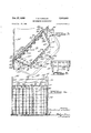
- Figure 1 is a horizontal-sectional,plan view of an incinerator constructed in accordance with my present invention
- Fig. 2 is a vertical sectional view taken substantially on the line 2 2 of Fig. 1, Vand looking in the direction of the arrows;
- Figs. 3, 4 and 5 are sectional elevational views, on -a larger scale, taken substantially on the lines 3 3, 4 4, and 5 5, respectively, of Figs. l and 2.'
- my vimproved incinera- .tor is shown as including two laterally oppositely extending furnace chamber portions 10, 11 arranged in parallel and having separate gratos, 15 although this is of course a matter of design and depends uponsuch factors as de'- sired capacity, and flexibility of operation. It will be apparent that a single furnace chamber might be ern'- ployed, or two or more single furnaces might be connected to a common combustion chamber by means of iudependent breechings.
- the two furnace chambers are rectangular and transversely aligned and are supported in an elevated position upon suitable supporting structural steel frameworkfcomp'rising steel supports as 12 and 14. The furnaces lare supported at a height such that trucks can be driven underneath.
- the grates shown are an inclined progressively burning type, higher at the back than at'the front, as shown in Fig. 2.
- the 'details of thegrates .form no part of my present' invention. 'The material to be burned is fed into the top of each furnace chamber at a lposition above the high part of the grate through a suitable hopper opening as 18.
- Air is also fed through the gratesfrom below and may be' controlled and distributed through suitable plenum chambers, not shown, in any of the vusual and well known Ways, and air may also be introduced through ports as 19 in the back wall.
- the air and gases of combustion, the ner particles of unburned material and ash entrained therewith move inwardly toward the center from the two furnace chambers, as shown by the arrows in Fig. l.
- the two furnace chambers are separated by a space, designated 20, which is enclosed by a bridge wall structure which partially encloses the two furnace chambers, and the width of such space substantially corresponds to the width of the breeching, designated 22, which connects the space 20 and thus the two furnace chambers 10, 11 to the combustion chamber 24,
- a space designated 20
- a bridge wall structure which partially encloses the two furnace chambers
- the width of such space substantially corresponds to the width of the breeching, designated 22, which connects the space 20 and thus the two furnace chambers 10, 11 to the combustion chamber 24
- the details of construction of the walls are not shown as it will be appreciated that these are also subject to variation, but they are of course preferably lined with suitable refractory or other heat insulating or resistant material.
- the combustion chamber 24 is defined by walls which extend down to the ground level or to the level of the paving 28 which extends forwardly beneath the ash hopper 16.
- the roof, 30, of the combustion chamber is substantially level with the roof of the furnaces and of the breeching 22.
- the breeching 22 by virtue of this arrangement, enters the front wall 32 of the combustion chamber in the upper portion of the latter and preferably near one side, shown as near the right in Fig. 1.
- the outlet breeching 33 which connects the combustion chamber 24 to the stack 34 is located near the left wall 35 of the combustion chamber and near the bottom of the rear wall 36. Thus, ue gases are diverted both downwardly and to the left in their passage through and from the combustion chamber.
- the proportions and the elevations of combustion chamber 24 as shown are those used to meet a particular designed condition. The same results can be obtained with lower or higher elevations and proportions and by suitable arrangements of the exits and entrance flues.
- the combustion chamber preferably has a relatively large volume with relation to the furnace and breechings so that the velocity therein is substantially reduced.
- a washer-precipitator system 99 is located in the combustion chamber in a position which provides a spray curtain and a wet wash-down pipe and plate structure extending across the entrance to the outlet breeching 33.
- This system preferably includes four upright pipe supports 40, 41, 42 and 43, extending the full height of the combustion chamber.
- the vertical pipe 40 is located near the left wall 35 and spaced forwardly from the rear wall 36, while the vertical pipe 41 is located close to the corner defining the juncture of the rear wall 36 and the right wall of breeching 33.
- the vertical pipes 42, 43 are spaced forwardly of and closer together than pipes 40, 41, so that the four pipes lie at the corners of a gure of isosceles trapezoidal section, which extends angularly across the outlet corner of the combustion chamber.
- the vertical pipes 40, 41 are connected by a plurality of pipes 44, which are more nearly horizontal, although preferably inclined somewhat, to facilitate escape of steam. Pipes 44 are coplanar and spaced in a generally ladderlike arrangement.
- the vertical pipes 42, 43 are similarly connected by a plurality of transverse pipes 45 and vertical pipes 40-42 are connected in like fashion by transverse pipes 46, while vertical pipes 41-43 are connected in like fashion by transverse pipes 48. Each series of transverse pipes lies in a common vertical plane. All of the described vertical and transverse pipes are interconnected with one another and are connected to a water inlet pipe 50. l
- a plurality of vertical .4 laterally spaced battle plates 60, 61, 62 which may be welded to the tubes 45 and are, as shown, spaced from one another a distance substantially equal to their width.
- the plate 60 is substantially sealed at its left edge with respect to the tube 42, While the plate 61 is substantially sealed at its right edge with respect to the tube 43.
- the baffle plates 60, 61, 62, and all of the other baffle plates of the system preferably extend vertically the full height of the combustion chamber and into substantially sealed engagement with the ceiling.
- the plates also etfect a seal at the oor, by reason of the fact that they extend below a constantly-maintained water level, as will presently appear, so that actual contact between the floor and the lower ends of the plates is not required.
- a plurality of outwardly projecting, welded-on supporting bars 64 are provided, which may also be formed of stainless steel, and to the outer ends of which additional outspaced baiiling plates 65 are welded in staggered relation to plates 60, 61, 62. Plates 65 are also of the full height of the combustion chamber, and are parallel to the previously mentioned plates.
- baffle plates as 70, 71, 72 is attached to the left bank of transverse tubes 46, and in similar fashion supports outwardly spaced baille plates 73, while the right bank of transverse tubes 48 similarly carries inner bale plates 76, 77, 78 and outer bale plates 80, all of the outer plates being held in outwardly spaced and staggered relation in similar fashion by welded stud-like supports 64.
- baffles are such as to permit free passage of the flue gases around the edges of and between the sets of inner and outer plates, and so into the interior of the generally trapezoidal space, designated 90, enclosed by the pipe and baflie plate structure.
- the baffle plates thus far described are located on the combustion chamber sides of the transverse vertical banks of tubes 45, 46, 48.
- a similar double series of vertically extending staggered am plates is provided on the rear bank of transverse tubes 44, the plates attached to the tubes 44 being designated 92, 94 and and being attached to the inside surfaces, that is, the surfaces near the combustion chamber, while the spaced bale plates 96 carried by .the tube-supported plates 92, 94, 95 are spaced inwardly and similarly carried by supporting bars 64, n such manner as to permit the gases to flow outwardly to the stack by passing around and through the spaces between the baffles and into the breeching 33.
- a water spray system is provided adapted to play against the surfaces of the bale plates on the combustion chamber sides of the plates carried by the transverse tubes 45, 46, 48, and to screen the spaces between the plates, such spray means comprising a pluralityof vertical spray water supply pipes as 100, 101, 102 and 103.
- the pipes 100, 101, 102, 103 extend the full vertical height of the combustion chamber, the pipe 100 being spaced from and substantially centered with respect to the baille system carried by the transverse tubes 46, the pipe 103 being similarly positioned with respect to the baffle system carried by the transverse tubes 48, and the pipes 101, 102 being appropriately positioned in similar fashion in front of the wider ba-le system carried by the transverse front pipes 45.
- spray nozzles as 104 are provided at vertically spaced positions along each of the pipes 100, 101, 102, 103 spray nozzles as 104 are provided .which are so spaced and are of such spray characteristics that the sprays from the nozzles carried by the pipe 100 play over the entire exposed surfaces of the battles carried by the transverse tubes 46, and the exposed portions of the vertical pipes 40, 42 on the same side of the structure, while the sprays from the pipes 100, 102 similarly blanket and completely'wet the entire front portion of the struc vcarried by thepipe 103 wetsand screens the'batlle structure carried by the tubes ⁇ also,lin-coohperation with the spray from the nozzles vcarriedby 'the pipe,1 ⁇ 0r24, wets the exposed portion of thepipe 43, and also Wets the surface of the pipe 4 1.
- the pipes ⁇ 100, 101, 102, A103 are directly connected to ⁇ the supplytSO of water under, pressure, and the water supplyis connected to the lower ends of the separate pipe structure ⁇ carriedlbyand connected to the vertical pipes 40,41, ft2', 43. v
- the vupperends of the vertical pipes 40, 42 extend into and lpartly upwardly .within an overflow tank 105 arranged above the ceiling of the combustion chamber.
- Thetank A105- is open ft'oatrnosphere, and all of the pipe structure comprising the pipes 40, 41, 42, ⁇ 43, 44, 4S, #Sand 48 communicates with the tank 105, so that any steam formed in this piping may escape from the tank.
- Arwater level is maintained iin the tank .105 above the tops "of the tubes 40,42.
- ⁇ An overflow pipe 106 is provided, the ,upperpend of whichis located in the tank ata level above the topslof lthe tubes 40, 42.
- the nozzles 108 are carried by transverse pipes as 110 supplied from the gravitydownflow pipe 1046 from the overlilow tank'105'through suitable horizontal branch pipes as 112 arranged .upon the rear side of the bank of transversetubes 44 and connected to the nozzles 10S by forwardly extending pipes as 114 which project through the baille structure to appropriate positions on the inside of the washer enclosure,'these nozzles being suitably spaced both vertically and horizontally so that the water ilowing from nozzles 1 08 completely wets the baille structure, providing effective entrapment of ily ash.
- nozzles 108 Due to the low pressure of the water from nozzles 108, these nozzles project the water onto the plates in the form of a stream, without'creating any material air-borne spray, so that there is less likelihood that water will be entrained with the portion of the gas which passes through the system and out through the breeching to the stack.
- the total amount of water supplied for both the front sprays fed bythe pipes 100, 101, 102, 103 and for the rear nozzles 108 is supplied at a rate greater than it can be evaporated,l so that it constantly flows downwardlyover the plates and piping structure while the incinerator is in operation, carrying with it solid particles, ash and dissolved gases and ooding the floor of the combustionchamber.
- the oor of the combustion chamber is inclined downwardly both from the front and the rear toward a gutter 54 which extends transversely across the combustion chamber and communicates with a ⁇ water discharge port 5S in the right side wall 38 of the combustion chamber.
- the port55 opens into the side of settling tank 56, which extends upwardly lto a height above the top of port 55, sopas to maintain a water level above the port in the combustion chamber and tank as indicated at WL in Fig. 2.
- the weir is preferably remoyable so that the combustion chamber 24 may be drained to remove accumulated solids, which may also be ushed out with suitable flushing nozzles, if required, although this will bers, as shown.
- VThe flushing nozzles are permanently installed in the-floor of the combustionpchamber, so that they may be turned on without interrupting the operation of the incinerator, and will intimately mix the solid material with the water and flush it out through the discharge port 55 and into the settling tank, from which' it may be removed by pumping or yany other suitable means.
- the gases are ordinarily still burning inthecombustion chamber l24 and as noted previously carry with them particles of burning material, incombustible material Yand ash. Many such particles Acontinue downwardly under the influence of inertia and gravity 'and strike the water and are of course vheld thereby. Any lighter particles which turn from their downward course into a more horizontal direction toward the left in such manner that they could enter the discharge breeching 33 above the water level are intercepted by the spray curtain and Aby the wet surfaces ⁇ of the washer structure. The water which flows downwardly over the pipes and plates washes particles which strike and adhere .to the wet surfaces continuously downwardly into the water. lt will also be appreciated that the gases are cooled by the water.
- the trapped and precipitated particles form a sludge with the water.
- the sludge water llows from the combustion chamber into ytank-'56 where the heavier solids settle out and the water passes over the removable Weir, and
- the water after removal of solid materials, is pumped back into the inlet 50 together with additional makeup water. lt will be noticed that the constant removal ofthe smaller precipitated particles from the combustion chamber by means of the excess water supply from the spray nozzles, the periodic removal of the larger particles bythe use of auxiliary jet nozzles, and the periodic removal of the settled solids from the tank in no Way interferes lwith the operation of the incinerator.
- the water exerts a powerful cooling inuence in the flue gases both as a spray and as an exposed surface on the bottom in addition to removing therefrom some of the volatile constituents including acids and corrosive and odiferous components.
- the linings of the outlet breeching and stackare thus prevented from being subjected to unduly high temperatures because a large proportion f 7 of the heat is used to evaporate some of ⁇ the water and is carried away and discharged through the stack as latent heat of vaporization.
- the cross sectional area of the combined combustion and precipitation chamber 24 is greater than the total cross-sectional area of the furnace chambers 10 and 11, so that the rate of travel of the gases and any entrained material is materially slowed in charnber 24, thereby assisting the precipitation and dropping out of such material.
- the volume of the chambers and the areas of the air admission ports are also great enough to permit the introduction of substantially more air than is required for combustion, and the system is operated with excess air, thereby assisting in maintaining low temperatures. Temperatures are also reduced by direct and evaporative water cooling, as noted above, and this greatly prolongs the useful life of the stack as Well as the other parts of the system.
- an incinerator comprising a furnace incineration chamber portion and a stak, a combined combustion and precipitation chamber portion interposed between said furnace chamber portion and stack, passage means providing communication between said chamber portions and of substantially smaller cross section than said combined combustion and precipitation chamber portion, means for maintaining a wet floor within at least a portion of said last-mentioned chamber portion, passage means connecting said last-mentioned chamber portion to the stack and also of lesser cross-sectional area than such chamber portion, and gas ow directing Wall portions for directing gases and products of combustion entering such chamber downwardly toward said wet floor, and wet-type screening means located in said last-mentioned chamber portion and at least partially blocking communication through said chamber portion to said stack, said screening means also being of substantially greater cross-sectional area than said passage means.
- an incerator having a furnace incineration cham'- ber portion, a combined combustion and precipitation chamber portion having an inlet communicating with said furnace chamber portion and having an outlet of lesser cross-sectional area than said combined combustion and precipitation chamber portion, and a wet-type screen in said combined combustion and precipitation chamber pori tion and spaced from said outlet and of greater crosssectional extent than said outlet and at least partially blocking communication between said inlet and outlet, said inlet from the furnace chamber portion being located higher than the oor of said combined combustion and precipitation chamber portion and said inlet discharging thereinto at an elevated position near one side of such combined combustion and precipitation chamber portion, said outlet communicating with a lower portion of said combined combustion and precipitation chamber portion at a position laterally spaced from said inlet.
- an incinerator comprising an elevated furnace incineration chamber portion, a combined combustion and a precipitation chamber portion at least a part of which extends downwardly below the furnace chamber portion, passage means interconnecting said chamber portions, passage means for connecting the second-mentioned Chamber portion to a stack, said second-mentionedchamber portion being of substantially greater cross section than both of said passage means, and wet-type precipitation means within said second-mentioned chamber portion including wash-down baffle structures extending across a substantially greater cross section than said passage and interposed in the path of ow through said cham- '8 ber portion, and water retaining oor portions in said second-mentioned chamber.
- an incinerator comprising an elevated furnace incineration chamber portion, a combined combustion and precipitation chamber portion at least a part of which extends downwardly below the furnace chamber portion, passage means interconnecting said chamber portions, passage.V means for connecting the second-mentioned chamber portion to a stack, said second-mentioned chamber portion being of substantially greater cross section than Vboth of said passage means, wet-type precipitation Vmeans within said second-mentioned chamber portion including wash-down bathe structures extending across a substantially greater cross section than said passage and interposed inthe path of ow through said chamber portion, and a wet floor portion in said chamber portion.
- an incinerator comprising an elevated furnace incineration chamber portion, a combined combustion and precipitation chamber portion at least a part of which extends downwardly below the furnace chamber portion, passage means interconnecting said chamber portions, passage means for connecting the second-mentioned chamber portion to a stack, said second-mentioned chamber portion being of substantially greater cross section than both of said passage means, wet-type precipitation means within said second-mentioned chamber portion including wash-down bafe structures extending across a substantially greater cross section than said passage and interposed in the path of ow through said chamber portion, and a wet floor portion in said chamber portion in the area between said aluminum structure and the first-mentioned passage means.
- an incinerator structure comprising a furnace incineration chamber portion and a stack, a combined combustion and precipitation chamber portion, passage means providing communication between said chamber portions and of smaller cross section than said combined combustion and precipitation chamber portion, means for maintaining a pool of water defining a wet oor within at least a portion of said last-mentioned chamber portion, passage means connecting said last-mentioned chamber portion to the stack and also of lesser cross-sectional area than said last-mentioned chamber portion, and gas iiow directing portions for directing gases and products of combustion entering said last-mentioned chamber portion downwardly toward said wet floor, and wet-type screening means located in said last-mentioned chamber portion and at least partially blocking communication through said chamber portion to said stack, said screening means also being of substantially greater cross-sectional area than said passage means.
- an incinerator comprising an elevated furnace incineration chamber portion, a combined combustion and precipitation chamber portion at least a part of which extends downwardly below the furnace chamber portion, passage means interconnecting said chamber portions, passage means for connecting the second-mentioned chamber portion to a stack, said second-mentioned chamber portion being of substantially greater cross section than each of said passage means, wet-type precipitation means within said second-mentioned chamber portion including wash-down articles structures extending across a substantially greater cross section than either of said passage means and interposed in the path of flow through said chamber portion, and a pool of water defining a oor in said chamber portion.
- an incinerator having a furnace incineration chamber portion, a combined combustion and precipitation chamber portion having an inlet communicating directly'with said furnace chamber portion and having an outlet of lesser cross-sectional area than said combined combustion and precipitation chamber portion, and a wettype screen in said combined combustion and precipitation chamber portion and spaced from said outlet and of greater GLOSS-sectional extent than said outlet and at least partially blocking communication between said inlet and outlet, said inlet opening into an upper area of said combined combustion and precipitation chamber portion and said last-mentioned chamber portion including ilow guiding portions tending to direct inflowing gases and products of combustion downwardly toward the iloor thereof, a sloping floor, and a water discharge portion communicating with a lower portion of said sloping floor at a position spaced from said wet-type screen, whereby excess water from said screen is directed downwardly by gravity'over said floor and through said discharge portion, and whereby the downwardly directed iniiowing gases and products of combustion may mingle with water vapor from the water on the
- an incinerator comprising a furnace incineration chamber portion and a stack, a combined combustion and precipitation chamber portion interposed between said furnace chamber portion and stack, passage means providing direct communicating between said furnace chamber portion and combined combustion and precipitation chamber portion and of smaller cross section than the latter, means for maintaining a wet floor within at least a portion of said last-mentioned chamber portion, passage means connecting said last-mentioned chamber portion to the stack and also of lesser-cross-sectional area than such chamber portion, and gas flow-directing wall portions for directing iniiowing gases and products of combustion entering such chamber downwardly toward said wet floor, whereby the downwardly directed inilowing gases and products of combustion may mingle with water Vapor from the water on the floor.
- an incinerator comprising a furnace incineration chamber portion and a stack and a combined combustion and precipitation chamber interposed between and directly communicating with both the stack and the furnace chamber portion and of substantially greater cross-sectional area in the direction of gas ow than the furnace chamber portion, wet-type separator means within said last-mentioned chamber portion and at least partially blocking flow through said chamber portion to the stack, said separator means including a bafe structure, means for spraying water toward and across said baffle structure to intercept gas and entrained particles passing through combustion entering said combined combustion and precipitation chamber downwardly toward said water retamlng portion to mingle with water vapor rising from the water, and whereby the gases of combustion are slowed in said combined combustion and precipitation chamber due to its greater cross-sectional area and due to the cooling effect of the Water and water vapor.
Description
061:. 27, 1959 T, E, wlNKLER 2,910,020
lINCINERTOR CONSTRUCTION Filed Dec. 27, 1955 2 Sheets-Sheet l OCI. 27, 1959 T, E, WINKLER 2,910,020
INCINERATOR CONSTRUCTION IN V EN TOR. re Y MPV/22? 7,
/y far/VEKST United States Patent "iiice .Patented Oct. 27, 1959 INCINERATQR CONSTRUCTION Theodore E.`Winkler,'Detroit, Mich.
. Application December '27 1955, Serial'No. l555,339
A 14 Claims. (Cl.'11o1s) This 'invention relates to the construction of incinerators and particularly to an improved incinerator for burning waste materials in large quantities as for example waste materials collected by municipal waste collection services, burnable industrial waste materials and the like. It .has heretofore been the practice in the construction of large incinerators to provide three or more large masonry `chambers serially connected by suitable breeching passages and vin turn connected to a stack. The first chamber is always the furnace chamber, containing grates and in which the major part of the combustion process takes place. This chamber is always connected by means of a breeching passage or bridge wall to a second chamber, known as the combustion chamber. The combustion chamber is usually designed for lower gas velocities than the furnace chamber, so that the volatile gases and small particles of unburned solid materials carried in the gases will have a further opportunity to burn to completion. `The large particles of ily-ash fall yto the floor in the combustion chamber because of the decrease in gas velocity. The gases from the combustion chamber then pass through an expansion chamber, which may be a separate chamber or a flue with a large cross-sectional area. The expansion chamber serves the purpose of again slowing down the gas velocities so that the particles of ay-ash not dropped in the combustion chamber will have another chance to settle out before the gases are discharged through some other chamber or to the stack. `Refractory .batlles or gas washersfmay be used in the expansion chambers or enlarged flues to assist in the removal of flyash. In the past, it has been common to approach the design problem from the standpoint of attempting to secure combustion which is as complete as possible in the furnace and combustion chamber, and to build additional chambers or ues to effectively remove -any remaining particles which might cause undue smoke and/or yash. My improved incinerator is based upon premises which are quite different however. I believe that the combustion chambers can be made to serve three useful purposes at onetime and thus eliminate the cost of building additional chambers or enlarged flues.
The three major problems confronting any incinerator designer for the section between the furnace and the chimney are the completion of combustion, the removal of fly-ash and the reduction of the gas temperature to a safe operating level for the refractories in the chimney.
The completion of combustion is a simple problem ofy providing adequate space and suitable velocities. The removal of fly-ash is a more difficult problem. Where the fly-ash particles fall to the floor, as in the conventional dry combustion or expansion chamber, they are not necessarilypermanently trapped. Increased gas velocity due to changes in air supply or chimney draft may cause trapped particles to become airborne again and carry them to some other portion of the system or up and out of the chimney. The third problem of reducing the temperature of the gases going to the stack can be solved by the 2 introduction :of cool air, water sprays or vby'waste heat utilization. Y
In my .improved incinerator, II take rcare of all three problems `in one chamber, in a manner which Vachieves high efliciency and a high capacity in "proportion to the size of the system. I provide facilities which will reduce the majority of the materials to .relatively Afine ash and which lwill reduce .the unbur-ned particles lto small size. In my improved incineraton'the combustion chamber is Vnot dry, as` is Vthe usual practice, but is y:providedl with a Wet `bottom and with a spray system. The combustion chamber is directly connected to the furnace by means of a bridge Vwall `or breech'ingand directly connected to the chimney by means -of a breeching, and forms the only major construction between thefurnaceiitself and the stack. The wetbottom of the combustion chambertraps any particles of :ily-ash or unburned solids which fall because of the vreduced gas velocity, and these trapped particles are effectively rstopped from ever again becoming airborne due to changes .in gas velocities. The gases in leaving .the combustion chamber are forced to pass through waterl sprays which reduce the gas temperature and which also reduces the gas velocities. This reduction in gas velocity together with `the washing action of the water further reduces the y-ash particles and unburned solids carried tothe chimney. The washing and cooling water containing the trapped particles falls to the wet bottom of the combustion chamber. The fly-ash and unburned particles which collect in the wet bottom of the combustion chamber are easily removed as required (without interfering with operation) by means of water jets which wash the solids to a settling tank located outside the combustion chamber. Y
Important objects andadvantages of my invention will be apparent from the foregoing discussion. Among these should be mentioned lowered first cost, lowered cost of operation and maintenance, reduced size, and elimination of furnace shutdown for the removal of y-ash. Other objects and advantages will be apparent upon consideration of the present disclosures in its entirety.
In the drawing:
Figure 1 is a horizontal-sectional,plan view of an incinerator constructed in accordance with my present invention;
Fig. 2 is a vertical sectional view taken substantially on the line 2 2 of Fig. 1, Vand looking in the direction of the arrows; and
Figs. 3, 4 and 5 are sectional elevational views, on -a larger scale, taken substantially on the lines 3 3, 4 4, and 5 5, respectively, of Figs. l and 2.'
Referring now to the drawing, my vimproved incinera- .tor is shown as including two laterally oppositely extending furnace chamber portions 10, 11 arranged in parallel and having separate gratos, 15 although this is of course a matter of design and depends uponsuch factors as de'- sired capacity, and flexibility of operation. It will be apparent that a single furnace chamber might be ern'- ployed, or two or more single furnaces might be connected to a common combustion chamber by means of iudependent breechings. The two furnace chambers are rectangular and transversely aligned and are supported in an elevated position upon suitable supporting structural steel frameworkfcomp'rising steel supports as 12 and 14. The furnaces lare supported at a height such that trucks can be driven underneath. to receive material dumped from the grates, 15, although they might 'be at a lower elevation if the ashes were to `be'r'et'rloir'edbyY -a conveyor system or some othermeans. The grates shown are an inclined progressively burning type, higher at the back than at'the front, as shown in Fig. 2. The 'details of thegrates .form no part of my present' invention. 'The material to be burned is fed into the top of each furnace chamber at a lposition above the high part of the grate through a suitable hopper opening as 18.
Air is also fed through the gratesfrom below and may be' controlled and distributed through suitable plenum chambers, not shown, in any of the vusual and well known Ways, and air may also be introduced through ports as 19 in the back wall. The air and gases of combustion, the ner particles of unburned material and ash entrained therewith move inwardly toward the center from the two furnace chambers, as shown by the arrows in Fig. l. As also shown in that view, the two furnace chambers are separated by a space, designated 20, which is enclosed by a bridge wall structure which partially encloses the two furnace chambers, and the width of such space substantially corresponds to the width of the breeching, designated 22, which connects the space 20 and thus the two furnace chambers 10, 11 to the combustion chamber 24, The details of construction of the walls are not shown as it will be appreciated that these are also subject to variation, but they are of course preferably lined with suitable refractory or other heat insulating or resistant material.
The combustion chamber 24 is defined by walls which extend down to the ground level or to the level of the paving 28 which extends forwardly beneath the ash hopper 16. The roof, 30, of the combustion chamber is substantially level with the roof of the furnaces and of the breeching 22. The breeching 22, by virtue of this arrangement, enters the front wall 32 of the combustion chamber in the upper portion of the latter and preferably near one side, shown as near the right in Fig. 1.
The outlet breeching 33 which connects the combustion chamber 24 to the stack 34 is located near the left wall 35 of the combustion chamber and near the bottom of the rear wall 36. Thus, ue gases are diverted both downwardly and to the left in their passage through and from the combustion chamber. The proportions and the elevations of combustion chamber 24 as shown are those used to meet a particular designed condition. The same results can be obtained with lower or higher elevations and proportions and by suitable arrangements of the exits and entrance flues. In any event, however, the combustion chamber preferably has a relatively large volume with relation to the furnace and breechings so that the velocity therein is substantially reduced.
A washer-precipitator system 99 is located in the combustion chamber in a position which provides a spray curtain and a wet wash-down pipe and plate structure extending across the entrance to the outlet breeching 33. This system preferably includes four upright pipe supports 40, 41, 42 and 43, extending the full height of the combustion chamber. The vertical pipe 40 is located near the left wall 35 and spaced forwardly from the rear wall 36, while the vertical pipe 41 is located close to the corner defining the juncture of the rear wall 36 and the right wall of breeching 33. The vertical pipes 42, 43 are spaced forwardly of and closer together than pipes 40, 41, so that the four pipes lie at the corners of a gure of isosceles trapezoidal section, which extends angularly across the outlet corner of the combustion chamber. The vertical pipes 40, 41 are connected by a plurality of pipes 44, which are more nearly horizontal, although preferably inclined somewhat, to facilitate escape of steam. Pipes 44 are coplanar and spaced in a generally ladderlike arrangement. The vertical pipes 42, 43 are similarly connected by a plurality of transverse pipes 45 and vertical pipes 40-42 are connected in like fashion by transverse pipes 46, while vertical pipes 41-43 are connected in like fashion by transverse pipes 48. Each series of transverse pipes lies in a common vertical plane. All of the described vertical and transverse pipes are interconnected with one another and are connected to a water inlet pipe 50. l
Attached to the front faces of the tubes 45, which lie in a common vertical plane, are a plurality of vertical .4 laterally spaced battle plates 60, 61, 62 which may be welded to the tubes 45 and are, as shown, spaced from one another a distance substantially equal to their width. As shown in Fig. 3, the plate 60 is substantially sealed at its left edge with respect to the tube 42, While the plate 61 is substantially sealed at its right edge with respect to the tube 43. The baffle plates 60, 61, 62, and all of the other baffle plates of the system, preferably extend vertically the full height of the combustion chamber and into substantially sealed engagement with the ceiling. The plates also etfect a seal at the oor, by reason of the fact that they extend below a constantly-maintained water level, as will presently appear, so that actual contact between the floor and the lower ends of the plates is not required.
At vertically spaced points along the front face of the plate 60, near the right edge thereof, and at similar positions along and near the left edge of the front face of plate 61, and along both edges of intermediate plates 62, a plurality of outwardly projecting, welded-on supporting bars 64 are provided, which may also be formed of stainless steel, and to the outer ends of which additional outspaced baiiling plates 65 are welded in staggered relation to plates 60, 61, 62. Plates 65 are also of the full height of the combustion chamber, and are parallel to the previously mentioned plates. A similar series of baffle plates as 70, 71, 72 is attached to the left bank of transverse tubes 46, and in similar fashion supports outwardly spaced baille plates 73, while the right bank of transverse tubes 48 similarly carries inner bale plates 76, 77, 78 and outer bale plates 80, all of the outer plates being held in outwardly spaced and staggered relation in similar fashion by welded stud-like supports 64.
It will be seen that the arrangement and support of the baffles is such as to permit free passage of the flue gases around the edges of and between the sets of inner and outer plates, and so into the interior of the generally trapezoidal space, designated 90, enclosed by the pipe and baflie plate structure. The baffle plates thus far described are located on the combustion chamber sides of the transverse vertical banks of tubes 45, 46, 48. A similar double series of vertically extending staggered baie plates is provided on the rear bank of transverse tubes 44, the plates attached to the tubes 44 being designated 92, 94 and and being attached to the inside surfaces, that is, the surfaces near the combustion chamber, while the spaced bale plates 96 carried by .the tube-supported plates 92, 94, 95 are spaced inwardly and similarly carried by supporting bars 64, n such manner as to permit the gases to flow outwardly to the stack by passing around and through the spaces between the baffles and into the breeching 33.
A water spray system is provided adapted to play against the surfaces of the bale plates on the combustion chamber sides of the plates carried by the transverse tubes 45, 46, 48, and to screen the spaces between the plates, such spray means comprising a pluralityof vertical spray water supply pipes as 100, 101, 102 and 103. The pipes 100, 101, 102, 103 extend the full vertical height of the combustion chamber, the pipe 100 being spaced from and substantially centered with respect to the baille system carried by the transverse tubes 46, the pipe 103 being similarly positioned with respect to the baffle system carried by the transverse tubes 48, and the pipes 101, 102 being appropriately positioned in similar fashion in front of the wider ba-le system carried by the transverse front pipes 45. At vertically spaced positions along each of the pipes 100, 101, 102, 103 spray nozzles as 104 are provided .which are so spaced and are of such spray characteristics that the sprays from the nozzles carried by the pipe 100 play over the entire exposed surfaces of the battles carried by the transverse tubes 46, and the exposed portions of the vertical pipes 40, 42 on the same side of the structure, while the sprays from the pipes 100, 102 similarly blanket and completely'wet the entire front portion of the struc vcarried by thepipe 103 wetsand screens the'batlle structure carried by the tubes` also,lin-coohperation with the spray from the nozzles vcarriedby 'the pipe,1`0r24, wets the exposed portion of thepipe 43, and also Wets the surface of the pipe 4 1. The pipes `100, 101, 102, A103 are directly connected to `the supplytSO of water under, pressure, and the water supplyis connected to the lower ends of the separate pipe structure `carriedlbyand connected to the vertical pipes 40,41, ft2', 43. v
As best shown in Fig. 5v, the vupperends of the vertical pipes 40, 42 extend into and lpartly upwardly .within an overflow tank 105 arranged above the ceiling of the combustion chamber. Thetank A105- is open ft'oatrnosphere, and all of the pipe structure comprising the pipes 40, 41, 42, `43, 44, 4S, #Sand 48 communicates with the tank 105, so that any steam formed in this piping may escape from the tank. Arwater level is maintained iin the tank .105 above the tops "of the tubes 40,42. `An overflow pipe 106 is provided, the ,upperpend of whichis located in the tank ata level above the topslof lthe tubes 40, 42. The excess water overflows through the pipe106,-which, as will be seen, maintains the level, sovthatv the tubes 40, 42 and the entire connected pipe structure comprising these pipes and the pipes I41, 43, and theconnecting transverse pipes are always flooded. v i Y Excess water is supplied, and ows downwardly through the overilow pipe 106, from which itis fed through suitable piping to nozzles S located within the space r90 and arranged to wet the internal baille structure carried by the rear transverse tubesflfl.'V i Y As brought out innFig. 3, the nozzles 108 are carried by transverse pipes as 110 supplied from the gravitydownflow pipe 1046 from the overlilow tank'105'through suitable horizontal branch pipes as 112 arranged .upon the rear side of the bank of transversetubes 44 and connected to the nozzles 10S by forwardly extending pipes as 114 which project through the baille structure to appropriate positions on the inside of the washer enclosure,'these nozzles being suitably spaced both vertically and horizontally so that the water ilowing from nozzles 1 08 completely wets the baille structure, providing effective entrapment of ily ash. Due to the low pressure of the water from nozzles 108, these nozzles project the water onto the plates in the form of a stream, without'creating any material air-borne spray, so that there is less likelihood that water will be entrained with the portion of the gas which passes through the system and out through the breeching to the stack. The total amount of water supplied for both the front sprays fed bythe pipes 100, 101, 102, 103 and for the rear nozzles 108 is supplied at a rate greater than it can be evaporated,l so that it constantly flows downwardlyover the plates and piping structure while the incinerator is in operation, carrying with it solid particles, ash and dissolved gases and ooding the floor of the combustionchamber.
The oor of the combustion chamber, designated 52, is inclined downwardly both from the front and the rear toward a gutter 54 which extends transversely across the combustion chamber and communicates with a` water discharge port 5S in the right side wall 38 of the combustion chamber. The port55, opens into the side of settling tank 56, which extends upwardly lto a height above the top of port 55, sopas to maintain a water level above the port in the combustion chamber and tank as indicated at WL in Fig. 2.
The water leaves the settling tank 56 by flowing over a Weir 57. The weir is preferably remoyable so that the combustion chamber 24 may be drained to remove accumulated solids, which may also be ushed out with suitable flushing nozzles, if required, although this will bers, as shown. VThe flushing nozzles are permanently installed in the-floor of the combustionpchamber, so that they may be turned on without interrupting the operation of the incinerator, and will intimately mix the solid material with the water and flush it out through the discharge port 55 and into the settling tank, from which' it may be removed by pumping or yany other suitable means. The gases are ordinarily still burning inthecombustion chamber l24 and as noted previously carry with them particles of burning material, incombustible material Yand ash. Many such particles Acontinue downwardly under the influence of inertia and gravity 'and strike the water and are of course vheld thereby. Any lighter particles which turn from their downward course into a more horizontal direction toward the left in such manner that they could enter the discharge breeching 33 above the water level are intercepted by the spray curtain and Aby the wet surfaces `of the washer structure. The water which flows downwardly over the pipes and plates washes particles which strike and adhere .to the wet surfaces continuously downwardly into the water. lt will also be appreciated that the gases are cooled by the water.
The trapped and precipitated particles form a sludge with the water. The sludge water llows from the combustion chamber into ytank-'56 where the heavier solids settle out and the water passes over the removable Weir, and
then through a pipe P tothe sewer, or the water maybe recirculated if desired.
1t will lbe recognized that Vthere is a constant flow of water downwardly over A.the `inclined floor surfaces 52 and outwardly through the `gutter 54 and port l55 and into the tank 56, reducing the tendency of solid materials vto accumulate in thecombustion chamber and facilitating the handling and removal of vsuch material. The heavierma- .terials which do settle in the combustion chamber can be removed periodically as required by means of auxiliary flushing water jets, lasnoted, and lthese preferably direct a vilow of water along theiloor lsurfaces 52 and through gutter 54 to give additional impetus to the water ow. If it is to be recirculated, the water, after removal of solid materials, is pumped back into the inlet 50 together with additional makeup water. lt will be noticed that the constant removal ofthe smaller precipitated particles from the combustion chamber by means of the excess water supply from the spray nozzles, the periodic removal of the larger particles bythe use of auxiliary jet nozzles, and the periodic removal of the settled solids from the tank in no Way interferes lwith the operation of the incinerator.
The water system shown is of course a -matter of design, and it is apparent that other arrangements or systems could also be used. Tests have shown that the use of the wet bottom and large combustion chamber without any washer will greatly reduce the fly-ash and unburned solids discharged to the chimney and no further cleaning of the gases may be necessary in some cases. It appears that the liberation of water vapor from the surface of the wet bottom to the hot gases materially reduces their ability to carry suspended solids and causes an increased dropping out. It would also bepossible under some conditions to use a spray or wet plate washer at the exit side of the combustion chamber with a wet bottom limited vto the floor space directly below the washer.
The water exerts a powerful cooling inuence in the flue gases both as a spray and as an exposed surface on the bottom in addition to removing therefrom some of the volatile constituents including acids and corrosive and odiferous components. The linings of the outlet breeching and stackare thus prevented from being subjected to unduly high temperatures because a large proportion f 7 of the heat is used to evaporate some of `the water and is carried away and discharged through the stack as latent heat of vaporization.
It is to be no ted thatthe cross sectional area of the combined combustion and precipitation chamber 24 is greater than the total cross-sectional area of the furnace chambers 10 and 11, so that the rate of travel of the gases and any entrained material is materially slowed in charnber 24, thereby assisting the precipitation and dropping out of such material. The volume of the chambers and the areas of the air admission ports are also great enough to permit the introduction of substantially more air than is required for combustion, and the system is operated with excess air, thereby assisting in maintaining low temperatures. Temperatures are also reduced by direct and evaporative water cooling, as noted above, and this greatly prolongs the useful life of the stack as Well as the other parts of the system.
While it will be apparent that the preferred embodiment of the invention herein described is well calculated to fill the objects and advantages first above stated, it will be appreciated that the invention is susceptible to variation, modification and change without departing from the fair meaning and proper scope of the appended claims.
What is claimed is:
1. In an incinerator comprising a furnace incineration chamber portion and a stak, a combined combustion and precipitation chamber portion interposed between said furnace chamber portion and stack, passage means providing communication between said chamber portions and of substantially smaller cross section than said combined combustion and precipitation chamber portion, means for maintaining a wet floor within at least a portion of said last-mentioned chamber portion, passage means connecting said last-mentioned chamber portion to the stack and also of lesser cross-sectional area than such chamber portion, and gas ow directing Wall portions for directing gases and products of combustion entering such chamber downwardly toward said wet floor, and wet-type screening means located in said last-mentioned chamber portion and at least partially blocking communication through said chamber portion to said stack, said screening means also being of substantially greater cross-sectional area than said passage means.
2. In an incerator having a furnace incineration cham'- ber portion, a combined combustion and precipitation chamber portion having an inlet communicating with said furnace chamber portion and having an outlet of lesser cross-sectional area than said combined combustion and precipitation chamber portion, and a wet-type screen in said combined combustion and precipitation chamber pori tion and spaced from said outlet and of greater crosssectional extent than said outlet and at least partially blocking communication between said inlet and outlet, said inlet from the furnace chamber portion being located higher than the oor of said combined combustion and precipitation chamber portion and said inlet discharging thereinto at an elevated position near one side of such combined combustion and precipitation chamber portion, said outlet communicating with a lower portion of said combined combustion and precipitation chamber portion at a position laterally spaced from said inlet.
3. In an incinerator comprising an elevated furnace incineration chamber portion, a combined combustion and a precipitation chamber portion at least a part of which extends downwardly below the furnace chamber portion, passage means interconnecting said chamber portions, passage means for connecting the second-mentioned Chamber portion to a stack, said second-mentionedchamber portion being of substantially greater cross section than both of said passage means, and wet-type precipitation means within said second-mentioned chamber portion including wash-down baffle structures extending across a substantially greater cross section than said passage and interposed in the path of ow through said cham- '8 ber portion, and water retaining oor portions in said second-mentioned chamber.
4. In an incinerator `comprising an elevated furnace incineration chamber portion, a combined combustion and precipitation chamber portion at least a part of which extends downwardly below the furnace chamber portion, passage means interconnecting said chamber portions, passage.V means for connecting the second-mentioned chamber portion to a stack, said second-mentioned chamber portion being of substantially greater cross section than Vboth of said passage means, wet-type precipitation Vmeans within said second-mentioned chamber portion including wash-down bathe structures extending across a substantially greater cross section than said passage and interposed inthe path of ow through said chamber portion, and a wet floor portion in said chamber portion.
5. In an incinerator comprising an elevated furnace incineration chamber portion, a combined combustion and precipitation chamber portion at least a part of which extends downwardly below the furnace chamber portion, passage means interconnecting said chamber portions, passage means for connecting the second-mentioned chamber portion to a stack, said second-mentioned chamber portion being of substantially greater cross section than both of said passage means, wet-type precipitation means within said second-mentioned chamber portion including wash-down bafe structures extending across a substantially greater cross section than said passage and interposed in the path of ow through said chamber portion, and a wet floor portion in said chamber portion in the area between said baie structure and the first-mentioned passage means.
6. In an incinerator structure comprising a furnace incineration chamber portion and a stack, a combined combustion and precipitation chamber portion, passage means providing communication between said chamber portions and of smaller cross section than said combined combustion and precipitation chamber portion, means for maintaining a pool of water defining a wet oor within at least a portion of said last-mentioned chamber portion, passage means connecting said last-mentioned chamber portion to the stack and also of lesser cross-sectional area than said last-mentioned chamber portion, and gas iiow directing portions for directing gases and products of combustion entering said last-mentioned chamber portion downwardly toward said wet floor, and wet-type screening means located in said last-mentioned chamber portion and at least partially blocking communication through said chamber portion to said stack, said screening means also being of substantially greater cross-sectional area than said passage means.
7. In an incinerator comprising an elevated furnace incineration chamber portion, a combined combustion and precipitation chamber portion at least a part of which extends downwardly below the furnace chamber portion, passage means interconnecting said chamber portions, passage means for connecting the second-mentioned chamber portion to a stack, said second-mentioned chamber portion being of substantially greater cross section than each of said passage means, wet-type precipitation means within said second-mentioned chamber portion including wash-down baie structures extending across a substantially greater cross section than either of said passage means and interposed in the path of flow through said chamber portion, and a pool of water defining a oor in said chamber portion.
8. In an incinerator having a furnace incineration chamber portion, a combined combustion and precipitation chamber portion having an inlet communicating directly'with said furnace chamber portion and having an outlet of lesser cross-sectional area than said combined combustion and precipitation chamber portion, and a wettype screen in said combined combustion and precipitation chamber portion and spaced from said outlet and of greater GLOSS-sectional extent than said outlet and at least partially blocking communication between said inlet and outlet, said inlet opening into an upper area of said combined combustion and precipitation chamber portion and said last-mentioned chamber portion including ilow guiding portions tending to direct inflowing gases and products of combustion downwardly toward the iloor thereof, a sloping floor, and a water discharge portion communicating with a lower portion of said sloping floor at a position spaced from said wet-type screen, whereby excess water from said screen is directed downwardly by gravity'over said floor and through said discharge portion, and whereby the downwardly directed iniiowing gases and products of combustion may mingle with water vapor from the water on the floor.
9. In an incinerator as defined in claim 8, means for maintaining water upon said iloor at a predetermined level.
l0. In an incinerator comprising a furnace incineration chamber portion and a stack, a combined combustion and precipitation chamber portion interposed between said furnace chamber portion and stack, passage means providing direct communicating between said furnace chamber portion and combined combustion and precipitation chamber portion and of smaller cross section than the latter, means for maintaining a wet floor within at least a portion of said last-mentioned chamber portion, passage means connecting said last-mentioned chamber portion to the stack and also of lesser-cross-sectional area than such chamber portion, and gas flow-directing wall portions for directing iniiowing gases and products of combustion entering such chamber downwardly toward said wet floor, whereby the downwardly directed inilowing gases and products of combustion may mingle with water Vapor from the water on the floor.
11. An incinerator as defined in claim l wherein said first-mentioned passage means opens into said combined combustion and precipitation chamber portion at a position higher .than the second-mentioned passage means, whereby gases and material entrained therewith entering said chamber portion are induced to ow downwardly toward the wet floor and tend to mingle with water vapor rising from the wet oor and to decelerate due to the enlarged cross section of said chamber portion and due to the contraction thereof resulting from `the cooling eifect of the water vapor.
12. In an incinerator comprising a furnace incineration chamber portion and a stack and a combined combustion and precipitation chamber interposed between and directly communicating with both the stack and the furnace chamber portion and of substantially greater cross-sectional area in the direction of gas ow than the furnace chamber portion, wet-type separator means within said last-mentioned chamber portion and at least partially blocking flow through said chamber portion to the stack, said separator means including a bafe structure, means for spraying water toward and across said baffle structure to intercept gas and entrained particles passing through combustion entering said combined combustion and precipitation chamber downwardly toward said water retamlng portion to mingle with water vapor rising from the water, and whereby the gases of combustion are slowed in said combined combustion and precipitation chamber due to its greater cross-sectional area and due to the cooling efect of the Water and water vapor.
13. The method of operating an incinerator of the type having a furnace chamber, a stack, and a combined combustion and precipitation chamber interposed between the furnace chamber and the stack and providing communication therebetween through ports connecting said combined chamber to the furnace chamber and the stack, which por-ts are of substantially Ilesser cross-section than the oombined combustion and precipitation chamber, said method comprising supplying burning gases to an upper portion of said combined chamber, directing said burning gases downwardly within said combined chamber, and substantially reducing the rate of flow of such gases in said combined chamber, introducing water into said combined chamber in a quantity exceeding the evaporative capacity of the effective heating capacity of such gases during their passage through such combined chamber, maintaining a level of water in the bottom of said combined chamber, boiling water from the su-rface defined by said level, and removing from the bottom of the combined chamber and in intermixed form at least a portion of said water together with any material precipitated thereinto, and removing said gases from said combined chamber at a lower portion thereof.
14. The method defined in claim 13 wherein at least a portion of said water is introduced into said combined chamber by flowing the water downwardly over an eX- tended wash-down baffle structure having a surface area substantially exceeding the cross-section of said ports and extending across rthe path of gas ow from said chamber to the stack.
References Cited in the ile of this patent UNITED STATES PATENTS 1,178,365 Wasley Apr. 4, 1916 1,282,708 Oppenheim Oct. 22, 1918 1,320,852 Goubert Nov. 4, 1919 1,509,475 Harrison Sept. 23, 1924 1,579,642 Burns Apr. 6, 1926 1,952,389 Staples Mar. 27, 1934 1,991,828 Tynan Feb. 19, 1935 2,045,115 Allen et a1. June 23, 1936 2,045,519 Contant .Tune 23, 1936 2,057,579 Kurth Oot. 13, 1936 2,648,395 Pond Aug. 11, 1953 2,696,274 Old Dec. 7, 1954
Priority Applications (1)
| Application Number | Priority Date | Filing Date | Title |
|---|---|---|---|
| US555339A US2910020A (en) | 1955-12-27 | 1955-12-27 | Incinerator construction |
Applications Claiming Priority (1)
| Application Number | Priority Date | Filing Date | Title |
|---|---|---|---|
| US555339A US2910020A (en) | 1955-12-27 | 1955-12-27 | Incinerator construction |
Publications (1)
| Publication Number | Publication Date |
|---|---|
| US2910020A true US2910020A (en) | 1959-10-27 |
Family
ID=24216887
Family Applications (1)
| Application Number | Title | Priority Date | Filing Date |
|---|---|---|---|
| US555339A Expired - Lifetime US2910020A (en) | 1955-12-27 | 1955-12-27 | Incinerator construction |
Country Status (1)
| Country | Link |
|---|---|
| US (1) | US2910020A (en) |
Cited By (1)
| Publication number | Priority date | Publication date | Assignee | Title |
|---|---|---|---|---|
| US3162236A (en) * | 1960-06-03 | 1964-12-22 | British Petroleum Co | Apparatus for reducing smoke emission from elevated flare stacks |
Citations (12)
| Publication number | Priority date | Publication date | Assignee | Title |
|---|---|---|---|---|
| US1178365A (en) * | 1914-02-12 | 1916-04-04 | Thomas E Wasley | Incinerating plant. |
| US1282708A (en) * | 1917-06-07 | 1918-10-22 | Simon Rudolph Oppenheim | Apparatus for incinerating kelp and like materials. |
| US1320852A (en) * | 1919-11-04 | goubert | ||
| US1509475A (en) * | 1923-11-14 | 1924-09-23 | Harrison Charles | Wood-refuse destroyer |
| US1579642A (en) * | 1925-07-25 | 1926-04-06 | Howard E Burns | Incinerator |
| US1952389A (en) * | 1929-07-20 | 1934-03-27 | Francis C Williams | Incinerator |
| US1991828A (en) * | 1932-07-19 | 1935-02-19 | Hiler Engineering & Constructi | Incinerating furnace |
| US2045115A (en) * | 1930-07-03 | 1936-06-23 | John E Allen | Refuse destructor |
| US2045519A (en) * | 1933-12-21 | 1936-06-23 | Coutant Jay Gould | Purification of gases |
| US2057579A (en) * | 1934-04-04 | 1936-10-13 | Kurth Franz Josef | Apparatus for purifying and otherwise treating air |
| US2648395A (en) * | 1951-01-30 | 1953-08-11 | Jr Harry S Pond | Air cleaner for internal-combustion engines |
| US2696274A (en) * | 1953-06-15 | 1954-12-07 | Southern Lightweight Aggregate | Air and gas treatment system |
-
1955
- 1955-12-27 US US555339A patent/US2910020A/en not_active Expired - Lifetime
Patent Citations (12)
| Publication number | Priority date | Publication date | Assignee | Title |
|---|---|---|---|---|
| US1320852A (en) * | 1919-11-04 | goubert | ||
| US1178365A (en) * | 1914-02-12 | 1916-04-04 | Thomas E Wasley | Incinerating plant. |
| US1282708A (en) * | 1917-06-07 | 1918-10-22 | Simon Rudolph Oppenheim | Apparatus for incinerating kelp and like materials. |
| US1509475A (en) * | 1923-11-14 | 1924-09-23 | Harrison Charles | Wood-refuse destroyer |
| US1579642A (en) * | 1925-07-25 | 1926-04-06 | Howard E Burns | Incinerator |
| US1952389A (en) * | 1929-07-20 | 1934-03-27 | Francis C Williams | Incinerator |
| US2045115A (en) * | 1930-07-03 | 1936-06-23 | John E Allen | Refuse destructor |
| US1991828A (en) * | 1932-07-19 | 1935-02-19 | Hiler Engineering & Constructi | Incinerating furnace |
| US2045519A (en) * | 1933-12-21 | 1936-06-23 | Coutant Jay Gould | Purification of gases |
| US2057579A (en) * | 1934-04-04 | 1936-10-13 | Kurth Franz Josef | Apparatus for purifying and otherwise treating air |
| US2648395A (en) * | 1951-01-30 | 1953-08-11 | Jr Harry S Pond | Air cleaner for internal-combustion engines |
| US2696274A (en) * | 1953-06-15 | 1954-12-07 | Southern Lightweight Aggregate | Air and gas treatment system |
Cited By (1)
| Publication number | Priority date | Publication date | Assignee | Title |
|---|---|---|---|---|
| US3162236A (en) * | 1960-06-03 | 1964-12-22 | British Petroleum Co | Apparatus for reducing smoke emission from elevated flare stacks |
Similar Documents
| Publication | Publication Date | Title |
|---|---|---|
| US3731462A (en) | Air purification systems | |
| US4440098A (en) | Waste material incineration system and method | |
| US4098200A (en) | Low pollution solid waste burner | |
| US3788244A (en) | Combustion chamber including dry and wet collection of particulate matter | |
| US3267890A (en) | Municipal incinerator | |
| US2481504A (en) | Traveling grate incinerator for city refuse and the like | |
| CN201462855U (en) | Garbage harmless burning and processing device | |
| US3525309A (en) | Process and apparatus for cleaning furnace gases | |
| JPS59180215A (en) | Clinker preventive device of municipal waste incinerator | |
| US2976949A (en) | Apparatus for cleaning and purifying gaseous products of combustion | |
| US3504645A (en) | Enclosed conveyor return run for incinerators | |
| US2246349A (en) | Fly ash trap | |
| US2910020A (en) | Incinerator construction | |
| US3322508A (en) | Secondary burner for removing and burning any solid combustibles resulting from a primary municipal garbage or trash burner | |
| US3447287A (en) | Incinerator having improved scrubber | |
| US2678009A (en) | Incinerator | |
| WO1998015779A1 (en) | Method and apparatus for removing particulate material from a gas | |
| SU1781509A1 (en) | Boiler | |
| US3448704A (en) | Incinerator and fly ash separator structure therefor | |
| US4246850A (en) | Incinerator | |
| US3055320A (en) | Incinerator | |
| US1585754A (en) | Boiler apparatus for utilizing the waste gases from cement kilns | |
| TW202108940A (en) | Chimney-less waste treatment device comprising a first furnace body, a second furnace body, a sewage precipitation unit, and a control unit | |
| CA1055314A (en) | Incinerator | |
| GB1229014A (en) |