US2894350A - Strip clip for loading box magazines - Google Patents
Strip clip for loading box magazines Download PDFInfo
- Publication number
- US2894350A US2894350A US577482A US57748256A US2894350A US 2894350 A US2894350 A US 2894350A US 577482 A US577482 A US 577482A US 57748256 A US57748256 A US 57748256A US 2894350 A US2894350 A US 2894350A
- Authority
- US
- United States
- Prior art keywords
- magazine
- spring
- clip
- cartridges
- cartridge
- Prior art date
- Legal status (The legal status is an assumption and is not a legal conclusion. Google has not performed a legal analysis and makes no representation as to the accuracy of the status listed.)
- Expired - Lifetime
Links
- 210000002105 tongue Anatomy 0.000 description 9
- 239000011324 bead Substances 0.000 description 4
- 239000002184 metal Substances 0.000 description 4
- 230000037431 insertion Effects 0.000 description 3
- 238000003780 insertion Methods 0.000 description 3
- 230000008093 supporting effect Effects 0.000 description 2
- 230000006978 adaptation Effects 0.000 description 1
- 230000004075 alteration Effects 0.000 description 1
- 238000006243 chemical reaction Methods 0.000 description 1
- 230000000994 depressogenic effect Effects 0.000 description 1
- 230000003028 elevating effect Effects 0.000 description 1
- 230000007257 malfunction Effects 0.000 description 1
- 230000003014 reinforcing effect Effects 0.000 description 1
- 230000000452 restraining effect Effects 0.000 description 1
- 238000003466 welding Methods 0.000 description 1
Images


Classifications
-
- F—MECHANICAL ENGINEERING; LIGHTING; HEATING; WEAPONS; BLASTING
- F41—WEAPONS
- F41A—FUNCTIONAL FEATURES OR DETAILS COMMON TO BOTH SMALLARMS AND ORDNANCE, e.g. CANNONS; MOUNTINGS FOR SMALLARMS OR ORDNANCE
- F41A9/00—Feeding or loading of ammunition; Magazines; Guiding means for the extracting of cartridges
- F41A9/82—Reloading or unloading of magazines
- F41A9/83—Apparatus or tools for reloading magazines with unbelted ammunition, e.g. cartridge clips
- F41A9/84—Clips
Definitions
- This invention relates to the magazines for repeating, semi-automatic and full automatic firearms (for convenience hereinafter called automatic firearms) and has for its object the provision of certain improvements in the cartridge magazines therefor and an improved clip for loading the magazine. It is an object of the invention toiprovide an improved magazine and a strip clip for loading the magazine, and a combination of the 1mproved magazine and strip clip.
- the magazine of my invention may be generally similar to the box magazine used, for example, in the Browning Automatic Rifle, or the box magazines of other automatic rifles, but embodies an improved resilient lip means for restraining the upward movement of the cartridges.
- My invention provides two pivotally mounted lips which, in their operative position, hold the top cartridges in the magazine in position to be fed into the barrel, which lips can be turned downward on their pivots to positions inside the box of the magazine when loading the magazine from the top or mouth, and which can spring back to their operative position to hold the top cartridges.
- I provide relatively thick metal bases on the sides of the magazine and pivotally connect the lips thereto.
- the magazine sides are cut out at the top to provide swinging clearance for the lips. Lugs or stops are provided on the bases to limit the upward pivotal movement of the lips.
- My invention provides a strip clip for holding a plurality of cartridges, say 20 in two staggered rows of each, which can be inserted into the top or mouth of the magazine to load all the cartridges into the magazine at one time.
- the clip comprises a U-shaped frame having inwardly extending flanges, giving it the general crosssectional shape of a channel bar, preferably proportioned to receive two rows of cartridges in staggered, stacked relation between the flanges.
- the strip clip of the invention comprises spring pressed means for engaging the rim of the bottom cartridge to hold it in the clip, and other spring means to engage the nose of the same cartridge to hold it in position.
- the spring means for holding the rim and the spring means for holding the nose are so located in the frame that they hold the bottom cartridge in a substantially horizontal position with reference to a horizontally disposed barrel.
- the clip preferably includes a generally U-shaped fiat spring mounted within the open channel, one end of which provides the spring means for holding the rim of the bottom cartridge, and the other end provides a spring means for bearing against the bullets of the top cartridge of each row to press the cartridges downwardly into engagement with the spring means for holding the nose of the bottom cartridge.
- Suflicient space is provided between the inside ofthe frame so that the .flat spring can be in a series of waves which press the cartridges from the base, ends to the opposite side of the clip and in this manner provide such space as to permit the stack of cartridges to turn enough to change from their angular position at the top of the horizontal position at the bottom.
- the improved spring clip It is one of the important features of the improved spring clip that it can be pressed into the mouth of a suitable box magazine, and when the follower of the magazine reaches the bottom of the box and is turned to an angular position with respect to said horizontal position, the nose of the bottom cartridge is pushed upwardly and is released from the spring means which holds the nose. means holding the rim of the bottom cartridge and all of the cartridges can then be pushed out of the clip into the magazine, after which the clip can be pulled out of the magazine and discarded if desired.
- the improved magazine and spring clip of the inven tion are especially suitable for arms carried by the footsoldier, such as the 30 caliber rifle of the U.S. Army, but can be used in various types of military automatic rifles.
- the magazine can be used very advantageously with the Garand rifle by cutting an opening in the floorplate and making some alterations in the receiver so that the magazine can be inserted from below.
- the 20-round magazine of thetype used with the Browning Automaticv Rifle is suitable for conversion after removing the usual stiff spring-lips and replacing them with the pivoted and spring actuated lips of the invention. 7
- the invention very greatly reduces the weight that a foot soldier must carry in comparison with present equipment. For example, a soldier carrying rounds of ammunition for the Garand rifle is burdened with 12 lbs. 4.0 oz. of cartridges and clips. The invention not only reduces this weight by 3 lbs. 2.3 02., but the box magazine will hold 20 rounds or more if desired compared with the 8-round capacity of the Garand rifle.
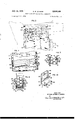
- FIG. 1 illustrates an embodiment of the invention in combination with the Garand rifle
- F Fig. 2 is a fragmentary enlarged sectional view of Fig. 3 is a view similar to Fig. 2 showing the initial insertion of the cartridges into the magazine
- Fig. 4 is a view similar to Fig. 2 showing the car-' tridges when in their final position at the bottom of the magazine;
- Fig. 5 is a fragmentary sectional view at 55 of Fig. 2;
- Fig. 6 is a fragmentary sectional view at 6-6 of.Fig. 3;
- Fig. 7 is a sectional view of the strip clip at 77 of Fig. 8; 1
- Fig. 8 is a sectional view of the strip clip at 8-8 of Fig. 7;
- Fig. 9 is a sectional View of the strip clip at 9-9 of Fig. 8, and
- Fig. 10 is an exploded view of a part of the strip clip.
- the improved strip clip and box magazine of the in vention will be described as usedin combinationwith a This same action also releases the spring modified Garand rifle. It is to be understood, however, that these elements of the invention may be adapted for use in connection with other automatic rifles.
- the box magazine illustrated is generally similar to the box magazine used on the Browning Automatic Rifle.
- the receiver 1 of the 'Garand rifle has been altered by the removal of some metal from the interior guides (not shown) in the receiver which hold the usual magazine clip, and by the opening of a rectangular hole in the floor plate 2 (Figs. 1, 2 and 3) for the insertion from below of the box magazine 3 which is removably secured in the receiver by the magazine catch 4.
- the magazine comprises an enclosing metal shell or box 5 having side Walls 6 and a bottom 7.
- the magazine includes the usual follower 8 which is held in an upward position by the spring 9.
- This magazine is constructed and proportioned to receive two columns of cartridges of ten each in staggered relation, and the magazine follower comprises a flat shelf portion 10, on which the bottom cartridge of one row rests and an offset elevated rib portion 11 on which the bottom cartridge of the other row rests (Fig. 6). These portions of the follower are inclined so as to give to the top cartridge, which is in loading position, such an angle with respect to the chamber of the barrel that it will be thrown into the chamber by the forward action of the breech block.
- the follower has depending legs 12 and 13 of such length that when the follower is pressed to the bottom of the magazine in engagement with the floor 7, as when the magazine is fully loaded, that the front or right hand portion of the follower as viewed in Fig. 4 is tilted upwardly.
- This is normally done in box magazines to make allowances for the tapered shape of the cartridge cases. While these are features common to box magazines of the type aforementioned, they play an important part in connection with the function of the strip clip of the invention.
- the usual box magazine for an automatic rifle comprises two curved lips in the form of stiff springs located on the opposite sides at the mouth of the magazine for the purpose of preventing the cartridges from being pushed out of the magazine by the spring and follower.
- the magazine of the invention does not employ these stiff springs but comprises two pivotally connected lips 14 and 15 which are arcuately shaped to conform to the cylindrical exterior of the cartridge case and are pivotally mounted on pins 16 and 17 which provide axes in a direction parallel to the sides of the magazine.
- Reinforcing U-shaped bases 18 and 19 are welded on to the sides of the magazine and have holes for the insertion of the pivot pins 16 and 17 therein.
- the upper sides of the magazine and the bases have openings 21 and 22 cut out for the clearance of the lips when they are swung to the position shown in Fig. 6.
- Coil springs 23 and 24 are mounted over the pins and have projecting terminals, one end of which bears against the base and the other against the lip so that the lip is normally held in the operative position shown in Fig. 5.
- the bottom cartridges of the clip engage the upper curved surfaces of the lipsand push them downwardly into openings 21 and 22 and into substantial parallelism with the sides 6 of the magazine as best shown in Fig. 6 in which position all of the cartridges may be pushed into the magazine.
- the rifle is preferably constructed to provide shoulders on the receiver to take the load oif the lips.
- the strip clip 32 comprises a generally U-shaped frame 33 having the cross section of a channel, with flat surfaces 34 and inwardly extending flanges 35 and 36.
- the left side or long leg of the clip as viewed in Fig. 8 has the edges of the flanges 35 and 36 turned inwardly to provide beads 37 and 38 which secure in the resulting pocket a flat thin spring 40.
- This spring as best shown in Fig. 8, has a curved upper portion and a wavy portion where it is inserted into the pocket. As thus constructed the spring bears on the flat surface 34 and on the inner surfaces of the beads 37 and 38.
- a flat tongue 41 is pressed out of the flat side of the channel and forms an inwardly extending stop.
- the spring has a hole 42 which fits over the tongue 41 and then the cross-bar 43 is slipped into place with the slot 44 straddling the tongue 41 and the flanged ends 45 and 46 slide under the beads 37 and 38 (Figs. 7 and 8).
- the tongue 41 not only holds the spring 40 in position but it serves as a stop for the top cartridge as shown in Fig. 7.
- the upper portion of the spring is cut to a narrower width than the portion held in the pocket of the long leg and has two spaced apart curved ends 47 and 48 which enter the short leg of the channel.
- the lower part of the spring on the long leg has two slits 49 and 50which form three separate tongues 52, 53 and 54.
- the central tongue 53 is bent inwardly at a slight angle so that it normally extends into the interior of the clip and requires some force to press it back into engagement with the flat surface 34 of the channel.
- the central tongue 53 has an attached thick catch 58 held in position by rivets 55 and 56. This catch has an arcuate bearing surface 57 which engages and holds in position the bottom cartridge (Fig. 2).
- a bracket 60 is welded to the inner face of the flat surface 34 of the short leg of the clip.
- This bracket receives a torsion spring 61 that has its upper end bent over and secured within the bracket so that this spring is prevented from rotation by reason of its secure mounting within the bracket.
- the lower portion of the pin passes through a hole in the lower bracket 62 and in which it is free to pivot.
- the lower end of the spring extends below the bracket 62 and has a hooked portion 63 which is approximately the shape and size of the nose portion of a bullet.
- This spring and its hooked portion are so constructed and mounted that when it is in its normal position it assumes the out-of-the-way position shown in Figs. 8 and 9.
- the flanges 35 and 36 are spaced apart a sufficient distance to engage and hold in position.
- the base of the uppermost cartridge strikes the tongue 41 and the nose of the bullet of this same cartridge bears against and is pressed down- Wardly by the curved end 48 of the spring, the lowermost cartridge which is in the opposite column bears against the arcuate surface 57 of the catch 58 and the base ends of all the cartridges are thus held in position.
- the operator turns the hook 63 of the spring 61 to the position shown in Fig. 2 and then releases his hold on the cartridges, the downward pressure exerted by the spring ends 47 and 48 holds all of the cartridges in position by reason of the engagement of the bottom cartridge with the hook 63.
- the loaded strip clip is inserted into the open mouth of the magazine by pressing it downwardly as shown in Figs. 1 and 2. It will be noted with reference to Figs. 2, 3 and 4, that the legs of the clip can fit inside the magazine and be pushed to the bottom.
- the bottom cartridges of the clip first engage the lips 14 and and push them downwardly in opposition to the springs 23 and 24 from the position shown in Fig. 5 to the position shown in Fig. 6.
- the mouth of the magazine is now open and both columns of cartridges engage the follower 8 of the magazine and can push it downwardly to the bottom as shown in Fig. 4.
- the legs 12 and 13 of the follower have different lengths, the leg 13 being proportioned so that the follower is tilted when it strikes the bottom, elevating the bullet portion of the bottom cartridge sufficiently to release the nose of the bullet from its engagement with the hook 63.
- the hook assumes an intermediate position between the two columns of bullets thereby releasing them completely.
- This same tilting of the bottom cartridges causes the heel of the cartridge engaging the catch 58 to pivot the tongue 53 and release the arcuate surface 57 from the rim of the cartridge. This tilting action frees the base and nose of the bottom cartridge, and when the clip is pulled upwardly all of the cartridges are left in the magazine.
- a strip clip for loading box magazines from the top which comprises a generally U-shaped channel frame having two legs, a first spring mounted within one leg and projecting across the top of the clip into contact with the other leg, the channel frame having inwardly extending flanges spaced apart so as to receive therebetween two rows of cartridges in staggered relation, said first spring contacting the top cartridge of each row, a catch on one end of the spring for engaging the rim of the bottom cartridge, a second spring mounted upon the other leg for engaging the bullet of the bottom cartridge, said first spring being efiective to apply pressure to the cartridges of each row to press the bullet of the bottom cartridge into secure engagement with the second spring, said catch and said second spring being releasable when said bottom cartridge is pushed upwardly, whereby all of the cartridges can be removed from the clip.
Landscapes
- Engineering & Computer Science (AREA)
- General Engineering & Computer Science (AREA)
- Toys (AREA)
Description
S. K. JANSON STRIP CLIP FOR LOADING BOX MAGAZINES Filed April 11, 1956 July 14, 1959 3 Sheets-Sheet 1 LvIIIPI ENTQR STEFAN KENNE HJANSON INV ATTORNEYS July 14, 1959 s. K. JANSON STRIP CLIP FOR LOADING BOX MAGAZINES Filed April 11. 1956 5 Sheets-Sheet 2 FIG.3
WAT/4,.
INVENTOR STEFAN KENNETH JANSON BY A" v flaw, WMVQMJ ATTORNEYS July 14, 1959 s. K. JANSON 2,894,350
I STRIP CLIP FOR LOADING BOX MAGAZINES Filed April 11, 1956 5 Sheets-Sheet 5 FIG. 8
FIG. 7
INVENTOR STEFAN KENNETH JANSON BY 7 f ul! FWHAW ATTORNEYS United States Patent 2,894,350 Fatented July 14, 1959 STRIP CLIP FOR LOADING BOX MAGAZINES Application April 11, 1956, Serial No. 577,482
4 Claims. (CI. 4287) This invention relates to the magazines for repeating, semi-automatic and full automatic firearms (for convenience hereinafter called automatic firearms) and has for its object the provision of certain improvements in the cartridge magazines therefor and an improved clip for loading the magazine. It is an object of the invention toiprovide an improved magazine and a strip clip for loading the magazine, and a combination of the 1mproved magazine and strip clip.
The magazine of my invention may be generally similar to the box magazine used, for example, in the Browning Automatic Rifle, or the box magazines of other automatic rifles, but embodies an improved resilient lip means for restraining the upward movement of the cartridges. My invention provides two pivotally mounted lips which, in their operative position, hold the top cartridges in the magazine in position to be fed into the barrel, which lips can be turned downward on their pivots to positions inside the box of the magazine when loading the magazine from the top or mouth, and which can spring back to their operative position to hold the top cartridges. In one adaptation of the invention I provide relatively thick metal bases on the sides of the magazine and pivotally connect the lips thereto. Preferably, the magazine sides are cut out at the top to provide swinging clearance for the lips. Lugs or stops are provided on the bases to limit the upward pivotal movement of the lips.
I prefer also to provide lugs or shoulders in the receiver of the rifle against which the lips hear, when in their operative position, to prevent the lips from being unduly deflected or damaged during operation of the rifle.
My invention provides a strip clip for holding a plurality of cartridges, say 20 in two staggered rows of each, which can be inserted into the top or mouth of the magazine to load all the cartridges into the magazine at one time. The clip comprises a U-shaped frame having inwardly extending flanges, giving it the general crosssectional shape of a channel bar, preferably proportioned to receive two rows of cartridges in staggered, stacked relation between the flanges. The strip clip of the invention comprises spring pressed means for engaging the rim of the bottom cartridge to hold it in the clip, and other spring means to engage the nose of the same cartridge to hold it in position. The spring means for holding the rim and the spring means for holding the nose are so located in the frame that they hold the bottom cartridge in a substantially horizontal position with reference to a horizontally disposed barrel. The clip preferably includes a generally U-shaped fiat spring mounted within the open channel, one end of which provides the spring means for holding the rim of the bottom cartridge, and the other end provides a spring means for bearing against the bullets of the top cartridge of each row to press the cartridges downwardly into engagement with the spring means for holding the nose of the bottom cartridge. Suflicient space is provided between the inside ofthe frame so that the .flat spring can be in a series of waves which press the cartridges from the base, ends to the opposite side of the clip and in this manner provide such space as to permit the stack of cartridges to turn enough to change from their angular position at the top of the horizontal position at the bottom.
It is one of the important features of the improved spring clip that it can be pressed into the mouth of a suitable box magazine, and when the follower of the magazine reaches the bottom of the box and is turned to an angular position with respect to said horizontal position, the nose of the bottom cartridge is pushed upwardly and is released from the spring means which holds the nose. means holding the rim of the bottom cartridge and all of the cartridges can then be pushed out of the clip into the magazine, after which the clip can be pulled out of the magazine and discarded if desired. There is an important coaction between the strip clip and the magaengage the lips and press the lips, inwardly and down-' Wardly, permitting the cartridges to press the magazine follower downwardly to the bottom of the magazine, and when this position has been reached, the top cartridges of the clip are inserted into the magazine to a position which permits the lips to snap upwardly to their operative position and hold the cartridges in proper position to be fed into the barrel chamber.
The improved magazine and spring clip of the inven tion are especially suitable for arms carried by the footsoldier, such as the 30 caliber rifle of the U.S. Army, but can be used in various types of military automatic rifles. The magazine can be used very advantageously with the Garand rifle by cutting an opening in the floorplate and making some alterations in the receiver so that the magazine can be inserted from below. The 20-round magazine of thetype used with the Browning Automaticv Rifle is suitable for conversion after removing the usual stiff spring-lips and replacing them with the pivoted and spring actuated lips of the invention. 7
The invention very greatly reduces the weight that a foot soldier must carry in comparison with present equipment. For example, a soldier carrying rounds of ammunition for the Garand rifle is burdened with 12 lbs. 4.0 oz. of cartridges and clips. The invention not only reduces this weight by 3 lbs. 2.3 02., but the box magazine will hold 20 rounds or more if desired compared with the 8-round capacity of the Garand rifle.
These and other novel features of the invention will be better understood after considering the following discussion taken in conjunction with the accompanying drawings, in which:
Fig. 1 illustrates an embodiment of the invention in combination with the Garand rifle; F Fig. 2 is a fragmentary enlarged sectional view of Fig. 3 is a view similar to Fig. 2 showing the initial insertion of the cartridges into the magazine; I
Fig. 4 is a view similar to Fig. 2 showing the car-' tridges when in their final position at the bottom of the magazine;
Fig. 5 is a fragmentary sectional view at 55 of Fig. 2;
Fig. 6 is a fragmentary sectional view at 6-6 of.Fig. 3;
Fig. 7 is a sectional view of the strip clip at 77 of Fig. 8; 1
Fig. 8 is a sectional view of the strip clip at 8-8 of Fig. 7;
Fig. 9 is a sectional View of the strip clip at 9-9 of Fig. 8, and
Fig. 10 is an exploded view of a part of the strip clip.
The improved strip clip and box magazine of the in vention will be described as usedin combinationwith a This same action also releases the spring modified Garand rifle. It is to be understood, however, that these elements of the invention may be adapted for use in connection with other automatic rifles. The box magazine illustrated is generally similar to the box magazine used on the Browning Automatic Rifle.
The receiver 1 of the 'Garand rifle has been altered by the removal of some metal from the interior guides (not shown) in the receiver which hold the usual magazine clip, and by the opening of a rectangular hole in the floor plate 2 (Figs. 1, 2 and 3) for the insertion from below of the box magazine 3 which is removably secured in the receiver by the magazine catch 4.
The magazine comprises an enclosing metal shell or box 5 having side Walls 6 and a bottom 7. The magazine includes the usual follower 8 which is held in an upward position by the spring 9. This magazine is constructed and proportioned to receive two columns of cartridges of ten each in staggered relation, and the magazine follower comprises a flat shelf portion 10, on which the bottom cartridge of one row rests and an offset elevated rib portion 11 on which the bottom cartridge of the other row rests (Fig. 6). These portions of the follower are inclined so as to give to the top cartridge, which is in loading position, such an angle with respect to the chamber of the barrel that it will be thrown into the chamber by the forward action of the breech block. The follower has depending legs 12 and 13 of such length that when the follower is pressed to the bottom of the magazine in engagement with the floor 7, as when the magazine is fully loaded, that the front or right hand portion of the follower as viewed in Fig. 4 is tilted upwardly. This is normally done in box magazines to make allowances for the tapered shape of the cartridge cases. While these are features common to box magazines of the type aforementioned, they play an important part in connection with the function of the strip clip of the invention.
The usual box magazine for an automatic rifle comprises two curved lips in the form of stiff springs located on the opposite sides at the mouth of the magazine for the purpose of preventing the cartridges from being pushed out of the magazine by the spring and follower. The magazine of the invention does not employ these stiff springs but comprises two pivotally connected lips 14 and 15 which are arcuately shaped to conform to the cylindrical exterior of the cartridge case and are pivotally mounted on pins 16 and 17 which provide axes in a direction parallel to the sides of the magazine. Reinforcing U-shaped bases 18 and 19 are welded on to the sides of the magazine and have holes for the insertion of the pivot pins 16 and 17 therein. The upper sides of the magazine and the bases have openings 21 and 22 cut out for the clearance of the lips when they are swung to the position shown in Fig. 6. Coil springs 23 and 24 are mounted over the pins and have projecting terminals, one end of which bears against the base and the other against the lip so that the lip is normally held in the operative position shown in Fig. 5. When a loaded strip clip is pushed into the magazine the bottom cartridges of the clip engage the upper curved surfaces of the lipsand push them downwardly into openings 21 and 22 and into substantial parallelism with the sides 6 of the magazine as best shown in Fig. 6 in which position all of the cartridges may be pushed into the magazine.
It requires a considerable force to restrain the upper movement of the cartridges in a fully loaded magazine because the spring 9 is depressed to its maximum extent and this places considerable strain on the lips and may result in such deformation as to result in malfunction. The rifle is preferably constructed to provide shoulders on the receiver to take the load oif the lips. In the case of the Garand rifle, I prefer to modify the receiver by the addition to the inner walls of two inwardly extending supporting shoulders or stop lugs 26 and 27. These may be formed by welding pieces of metal to the receiver. As best shown in Fig. 5, the lips in their operative position are held upwardly by the springs 23 and 24 against stop projections 28 and 29 (Fig. 2) but in the preferred embodiment of the invention the supporting action of these stops is supplemented by the unyielding stop lugs 26 and 27 on the rigid frame of the receiver. It is, accordingly, impossible for the magazine spring to push the cartridges upwardly beyond these lugs.
The strip clip 32 comprises a generally U-shaped frame 33 having the cross section of a channel, with flat surfaces 34 and inwardly extending flanges 35 and 36. The left side or long leg of the clip as viewed in Fig. 8 has the edges of the flanges 35 and 36 turned inwardly to provide beads 37 and 38 which secure in the resulting pocket a flat thin spring 40. This spring, as best shown in Fig. 8, has a curved upper portion and a wavy portion where it is inserted into the pocket. As thus constructed the spring bears on the flat surface 34 and on the inner surfaces of the beads 37 and 38. As best shown in Fig. 10, a flat tongue 41 is pressed out of the flat side of the channel and forms an inwardly extending stop. The spring has a hole 42 which fits over the tongue 41 and then the cross-bar 43 is slipped into place with the slot 44 straddling the tongue 41 and the flanged ends 45 and 46 slide under the beads 37 and 38 (Figs. 7 and 8). The tongue 41 not only holds the spring 40 in position but it serves as a stop for the top cartridge as shown in Fig. 7.
The upper portion of the spring is cut to a narrower width than the portion held in the pocket of the long leg and has two spaced apart curved ends 47 and 48 which enter the short leg of the channel. The lower part of the spring on the long leg has two slits 49 and 50which form three separate tongues 52, 53 and 54. The central tongue 53 is bent inwardly at a slight angle so that it normally extends into the interior of the clip and requires some force to press it back into engagement with the flat surface 34 of the channel. The central tongue 53 has an attached thick catch 58 held in position by rivets 55 and 56. This catch has an arcuate bearing surface 57 which engages and holds in position the bottom cartridge (Fig. 2).
A bracket 60 is welded to the inner face of the flat surface 34 of the short leg of the clip. This bracket receives a torsion spring 61 that has its upper end bent over and secured within the bracket so that this spring is prevented from rotation by reason of its secure mounting within the bracket. The lower portion of the pin passes through a hole in the lower bracket 62 and in which it is free to pivot. The lower end of the spring extends below the bracket 62 and has a hooked portion 63 which is approximately the shape and size of the nose portion of a bullet. This spring and its hooked portion are so constructed and mounted that when it is in its normal position it assumes the out-of-the-way position shown in Figs. 8 and 9.
The flanges 35 and 36 are spaced apart a sufficient distance to engage and hold in position. two columns of cartridges of 20 rounds each. When all of the cartridges are inserted into the clip, the base of the uppermost cartridge strikes the tongue 41 and the nose of the bullet of this same cartridge bears against and is pressed down- Wardly by the curved end 48 of the spring, the lowermost cartridge which is in the opposite column bears against the arcuate surface 57 of the catch 58 and the base ends of all the cartridges are thus held in position. When all of the 20 cartridges are thus inserted into the clip the operator turns the hook 63 of the spring 61 to the position shown in Fig. 2 and then releases his hold on the cartridges, the downward pressure exerted by the spring ends 47 and 48 holds all of the cartridges in position by reason of the engagement of the bottom cartridge with the hook 63.
The loaded strip clip is inserted into the open mouth of the magazine by pressing it downwardly as shown in Figs. 1 and 2. It will be noted with reference to Figs. 2, 3 and 4, that the legs of the clip can fit inside the magazine and be pushed to the bottom. The bottom cartridges of the clip first engage the lips 14 and and push them downwardly in opposition to the springs 23 and 24 from the position shown in Fig. 5 to the position shown in Fig. 6. The mouth of the magazine is now open and both columns of cartridges engage the follower 8 of the magazine and can push it downwardly to the bottom as shown in Fig. 4. As mentioned previously, the legs 12 and 13 of the follower have different lengths, the leg 13 being proportioned so that the follower is tilted when it strikes the bottom, elevating the bullet portion of the bottom cartridge sufficiently to release the nose of the bullet from its engagement with the hook 63. By reason of the normal non-opposed position of the spring 61 is shown in Fig. 9, the hook assumes an intermediate position between the two columns of bullets thereby releasing them completely. This same tilting of the bottom cartridges causes the heel of the cartridge engaging the catch 58 to pivot the tongue 53 and release the arcuate surface 57 from the rim of the cartridge. This tilting action frees the base and nose of the bottom cartridge, and when the clip is pulled upwardly all of the cartridges are left in the magazine. When the cartridges are pushed downwardly to the position where they are released, as in Fig. 4, the uppermost cartridge of both columns are sufi'iciently within the magazine that they clear the lips 14 and 15, thus permitting them to spring upwardly to their normal operative position as shown in Fig. 5. The lips are stopped by the lugs 28 and 29 and are also supported by the inwardly projecting lugs 26 and 27 on the inner walls of the rifle.
I claim:
1. A strip clip for loading box magazines from the top which comprises a generally U-shaped channel frame having two legs, a first spring mounted within one leg and projecting across the top of the clip into contact with the other leg, the channel frame having inwardly extending flanges spaced apart so as to receive therebetween two rows of cartridges in staggered relation, said first spring contacting the top cartridge of each row, a catch on one end of the spring for engaging the rim of the bottom cartridge, a second spring mounted upon the other leg for engaging the bullet of the bottom cartridge, said first spring being efiective to apply pressure to the cartridges of each row to press the bullet of the bottom cartridge into secure engagement with the second spring, said catch and said second spring being releasable when said bottom cartridge is pushed upwardly, whereby all of the cartridges can be removed from the clip.
2. A strip clip for loading box magazines from the top as defined in claim 1, wherein the first spring is formed with a plurality of waves which apply pressure against the bases of the cartridges urging the bullets against the opposite face of the channel, the flanges on one side of the channel having inwardly turned beads which secure the first spring in position.
3. A strip clip for loading box magazines from the top as defined in claim 1 wherein the first spring is flat, split and terminates in a pair of curved ends, each end being operative to apply pressure to the bullet end of cartridges individual thereto.
4. A strip clip for loading box magazines from the top as defined in claim 1 wherein the second spring comprises a torsioned wire secured at one end to the channel frame and the opposite end thereof being formed with a bullet engaging hook, the normal position of said hook being free of the bullet.
References Cited in the file of this patent UNITED STATES PATENTS 578,931 Johnson Mar. 16, 1897 679,412 Bruce July 30, 1901 1,645,031 Frommer Oct. 11, 1927 1,732,949 Pedersen Oct. 22, 1929 2,192,677 Hoagland et a1. Mar. 5, 1940 2,197,313 Nomar Apr. 16, 1940 2,715,789 Garand Aug. 23, 1955 2,783,570 Kunz Mar. 5, 1957
Priority Applications (1)
| Application Number | Priority Date | Filing Date | Title |
|---|---|---|---|
| US577482A US2894350A (en) | 1956-04-11 | 1956-04-11 | Strip clip for loading box magazines |
Applications Claiming Priority (1)
| Application Number | Priority Date | Filing Date | Title |
|---|---|---|---|
| US577482A US2894350A (en) | 1956-04-11 | 1956-04-11 | Strip clip for loading box magazines |
Publications (1)
| Publication Number | Publication Date |
|---|---|
| US2894350A true US2894350A (en) | 1959-07-14 |
Family
ID=24308915
Family Applications (1)
| Application Number | Title | Priority Date | Filing Date |
|---|---|---|---|
| US577482A Expired - Lifetime US2894350A (en) | 1956-04-11 | 1956-04-11 | Strip clip for loading box magazines |
Country Status (1)
| Country | Link |
|---|---|
| US (1) | US2894350A (en) |
Cited By (10)
| Publication number | Priority date | Publication date | Assignee | Title |
|---|---|---|---|---|
| US3222810A (en) * | 1964-06-23 | 1965-12-14 | Daniel D Musgrave | Magazine loading clip |
| US4352254A (en) * | 1980-05-27 | 1982-10-05 | Kurt Peter | Cartridge package for rapid loading of a magazine or clip for automatic and semiautomatic weapons |
| US9335107B2 (en) | 2013-07-29 | 2016-05-10 | Bolt Action Concepts, Llc | Speed reloader for bolt action fixed rifle |
| US9574836B1 (en) * | 2016-02-04 | 2017-02-21 | Battenfeld Technologies, Inc. | Firearm magazine loader |
| US20180172378A1 (en) * | 2016-12-16 | 2018-06-21 | Mean Llc. | Firearm loader |
| US10175017B2 (en) | 2015-08-19 | 2019-01-08 | Battenfeld Technologies, Inc. | Firearm magazine loader having adjustable magazine well |
| US10222152B1 (en) * | 2018-02-08 | 2019-03-05 | Mark Ayers | Reloadable magazine apparatus configured to accept a plurality of cartridges |
| US10345065B2 (en) * | 2017-04-25 | 2019-07-09 | Richard Darin Roe | Rifle magazine loader apparatus |
| US20220282944A1 (en) * | 2021-03-02 | 2022-09-08 | Jordan Laycock | Hand operated, mechanical magazine loader, for ammunition on stripper clips |
| US20240077267A1 (en) * | 2022-06-21 | 2024-03-07 | James F Griffin | Ammunition Loading Device Design |
Citations (8)
| Publication number | Priority date | Publication date | Assignee | Title |
|---|---|---|---|---|
| US578931A (en) * | 1897-03-16 | Thomas c | ||
| US679412A (en) * | 1900-10-11 | 1901-07-30 | Lucien F Bruce | Cartridge-clip. |
| US1645031A (en) * | 1918-06-08 | 1927-10-11 | Frommer Rudolf Von | Cartridge magazine |
| US1732949A (en) * | 1928-01-14 | 1929-10-22 | John D Pedersen | Cartridge clip |
| US2192677A (en) * | 1936-06-20 | 1940-03-05 | Automatic Guns Inc | Cartridge feed for guns |
| US2197313A (en) * | 1936-11-21 | 1940-04-16 | Nomar Louis Nolan | Cartridge clip |
| US2715789A (en) * | 1949-05-26 | 1955-08-23 | John C Garand | Magazine for a firearm |
| US2783570A (en) * | 1954-04-29 | 1957-03-05 | William R Kunz | Magazine charger for firearms |
-
1956
- 1956-04-11 US US577482A patent/US2894350A/en not_active Expired - Lifetime
Patent Citations (8)
| Publication number | Priority date | Publication date | Assignee | Title |
|---|---|---|---|---|
| US578931A (en) * | 1897-03-16 | Thomas c | ||
| US679412A (en) * | 1900-10-11 | 1901-07-30 | Lucien F Bruce | Cartridge-clip. |
| US1645031A (en) * | 1918-06-08 | 1927-10-11 | Frommer Rudolf Von | Cartridge magazine |
| US1732949A (en) * | 1928-01-14 | 1929-10-22 | John D Pedersen | Cartridge clip |
| US2192677A (en) * | 1936-06-20 | 1940-03-05 | Automatic Guns Inc | Cartridge feed for guns |
| US2197313A (en) * | 1936-11-21 | 1940-04-16 | Nomar Louis Nolan | Cartridge clip |
| US2715789A (en) * | 1949-05-26 | 1955-08-23 | John C Garand | Magazine for a firearm |
| US2783570A (en) * | 1954-04-29 | 1957-03-05 | William R Kunz | Magazine charger for firearms |
Cited By (19)
| Publication number | Priority date | Publication date | Assignee | Title |
|---|---|---|---|---|
| US3222810A (en) * | 1964-06-23 | 1965-12-14 | Daniel D Musgrave | Magazine loading clip |
| US4352254A (en) * | 1980-05-27 | 1982-10-05 | Kurt Peter | Cartridge package for rapid loading of a magazine or clip for automatic and semiautomatic weapons |
| USD828894S1 (en) | 2013-07-29 | 2018-09-18 | Bolt Action Concepts, Llc | Reloader |
| US9335107B2 (en) | 2013-07-29 | 2016-05-10 | Bolt Action Concepts, Llc | Speed reloader for bolt action fixed rifle |
| US9612071B2 (en) | 2013-07-29 | 2017-04-04 | Bolt Action Concepts, Llc | Speed reloader for bolt action fixed rifle |
| US10641566B2 (en) | 2015-08-19 | 2020-05-05 | Battenfeld Technologies, Inc. | Handgun magazine loader having cartridge driver |
| US10330411B2 (en) | 2015-08-19 | 2019-06-25 | Battenfeld Technologies, Inc. | Handgun magazine loader having cartridge driver |
| US10175017B2 (en) | 2015-08-19 | 2019-01-08 | Battenfeld Technologies, Inc. | Firearm magazine loader having adjustable magazine well |
| US10830547B2 (en) | 2015-08-19 | 2020-11-10 | Aob Products Company | Firearm magazine loader having adjustable magazine well |
| US9574836B1 (en) * | 2016-02-04 | 2017-02-21 | Battenfeld Technologies, Inc. | Firearm magazine loader |
| US10598453B2 (en) * | 2016-12-16 | 2020-03-24 | Mean Llc | Firearm loader |
| US20180172378A1 (en) * | 2016-12-16 | 2018-06-21 | Mean Llc. | Firearm loader |
| US11674765B2 (en) | 2016-12-16 | 2023-06-13 | James Matthew Underwood | Firearm loader |
| US12140395B2 (en) | 2016-12-16 | 2024-11-12 | James Matthew Underwood | Firearm loader |
| US10345065B2 (en) * | 2017-04-25 | 2019-07-09 | Richard Darin Roe | Rifle magazine loader apparatus |
| US10222152B1 (en) * | 2018-02-08 | 2019-03-05 | Mark Ayers | Reloadable magazine apparatus configured to accept a plurality of cartridges |
| US20220282944A1 (en) * | 2021-03-02 | 2022-09-08 | Jordan Laycock | Hand operated, mechanical magazine loader, for ammunition on stripper clips |
| US11448475B1 (en) * | 2021-03-02 | 2022-09-20 | Trijent, Llc | Hand operated, mechanical magazine loader, for ammunition on stripper clips |
| US20240077267A1 (en) * | 2022-06-21 | 2024-03-07 | James F Griffin | Ammunition Loading Device Design |
Similar Documents
| Publication | Publication Date | Title |
|---|---|---|
| US2783570A (en) | Magazine charger for firearms | |
| US2834137A (en) | Magazing charger | |
| US2887811A (en) | Cartridge clip for loading box magazines | |
| US2894350A (en) | Strip clip for loading box magazines | |
| US9212859B1 (en) | Self-raising magazine loader | |
| US3509655A (en) | Pistol magazine follower depressor | |
| US5956878A (en) | Cartridge magazine for a firearm | |
| US2903809A (en) | Cartridge magazine of aluminum or magnesium | |
| GB316645A (en) | Automatic firearms | |
| US2081235A (en) | Firearm | |
| US2396816A (en) | Magazine conversion unit | |
| US12578157B2 (en) | Ammunition magazine | |
| US2997803A (en) | Removable magazine unit for bolt action rifle | |
| US1228505A (en) | Loading-pack for revolvers. | |
| US2359263A (en) | Automatic firearm and combined accessories | |
| US3110122A (en) | Firearm magazine with two oppositely disposed feed ends | |
| US2745203A (en) | Firearm cartridge protector | |
| US1306972A (en) | Cartridge-magazine for firearms | |
| US2856716A (en) | Automatic rifle with a combined movable chamber and magazine | |
| US1462972A (en) | Cartridge magazine | |
| US2434269A (en) | Firearm magazine | |
| US1858862A (en) | Firearm | |
| US2979992A (en) | Reversible feeding mechanism | |
| US1229721A (en) | Firearm. | |
| US3665631A (en) | Self contained magazine |