US288564A - To eogeb j - Google Patents
To eogeb j Download PDFInfo
- Publication number
- US288564A US288564A US288564DA US288564A US 288564 A US288564 A US 288564A US 288564D A US288564D A US 288564DA US 288564 A US288564 A US 288564A
- Authority
- US
- United States
- Prior art keywords
- vanes
- shield
- air
- building
- current
- Prior art date
- Legal status (The legal status is an assumption and is not a legal conclusion. Google has not performed a legal analysis and makes no representation as to the accuracy of the status listed.)
- Expired - Lifetime
Links
- 102100027069 Odontogenic ameloblast-associated protein Human genes 0.000 description 1
- 101710091533 Odontogenic ameloblast-associated protein Proteins 0.000 description 1
- 241001620634 Roger Species 0.000 description 1
- 239000003818 cinder Substances 0.000 description 1
- 239000000428 dust Substances 0.000 description 1
- 238000009423 ventilation Methods 0.000 description 1
Images
Classifications
-
- B—PERFORMING OPERATIONS; TRANSPORTING
- B61—RAILWAYS
- B61D—BODY DETAILS OR KINDS OF RAILWAY VEHICLES
- B61D27/00—Heating, cooling, ventilating, or air-conditioning
- B61D27/009—Means for ventilating only
Definitions
- My invention relates to a ventilator more 1o especially intended for cars, vessels, or moving conveyances or vehicles of any kind, it being automatically operated by the current of air produced by the movement of the said vehicles.
- the invention consists, essentially, in the combination of a shield and a series of vanes pivoted therein and connected together, and operated automatically by a current of air passing through the shield, substantially'as 2O hereinafter specifically set forth and claimed.
- the building or vehicle to be ventilated is provided ⁇ with openings, covered by the said shield, and the action' of the current of air passing therethrough and by the ends of the vanes is such as to produce an outward cur.- rent from the building or vehicle, thus removing the foul air.
- the extent of the openings through which the foul air thus escapes may be controlled by any suitable register.
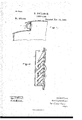
- Figure l is a transverse section of a portion of a car provided with a ventilator embodying this invention, and Fig. 2 a longitudinal section thereof on line x x on a larger scale.
- the ventilator (shown Vin this instance as applied to a railway-car A,) consists of a shield, a, U-shaped in cross-section, and containing a series of pivoted vanes, b, and being adapted to be fastened upon ⁇ the side of 4o the car or other building or structure to be ventilated, in such a manner that the movement of the said car produces a current of air longitudinally through the said shield a. (lndicated by the arrows 2, Fig. 2.)
- the vanes b are pivoted at that side of the shield adjacent to the car or building, and their free ends are thus acted upon bythe current ⁇ of air entering either end of the said shield, the vanes being turned on their pivots by the said current, so as to slant in the 5o A"direction ofthe said current, which, in passing by their ends, forms an exhaust, causing the air in Ithe car or building to be drawn outward between the said vanes, thus producing an outward current of air from the interior of the car or building, as indicated by the arrows 3, the said air passing through openings 4, connecting the interior of the structure with the interior of the ventilatorshield a.
- vanes ofthe series are joined 6o by a rod, c3, or equivalent, by which they are maintained parallel or uniformly spaced, and the extent of the movement of the vanes b on their pivots in either direction is limited by a suitable stop, (shown in this instance as cords or chains c, connected at one of their ends with the building or shield, and at their other end with the outermost vanes
- a suitable stop shown in this instance as cords or chains c, connected at one of their ends with the building or shield, and at their other end with the outermost vanes
- the amount of air flowing out from the car or building may be controlled by n suitable 7c slide or register, d, operated in any suitable or usual manner to wholly or partially cover the openings 4, or to leave them wholly open, according as more or less ventilation is required.
- vanes b and shield a afford a complete protection for the openings 4, so that it is impossible for dust or cinders to pass to the interior of the building or car.
- the ventilator When the ventilator is used upon a stationary structure or building, it may be necessary in some instances to produce an artificial current of air through the shield a.
- ROBERT FOULSHAM. 5 provided with suitable stops and the register witnesseses:
Landscapes
- Engineering & Computer Science (AREA)
- Mechanical Engineering (AREA)
- Blinds (AREA)
Description
" f UNrTED STATES PATENT O EEicE9 ROBERT EOULSHAM, OE BOSTON, MASSACHUSETTS, ASSIGNOR OE ONE-HALE -To ROGER J.'ELA, OE SAME BLAOE.
VENTILATOR.
SPECIFICATION forming part of Letters Patent No. 288,564, dated November 13, 1883. Application inea Apin 4, resa. (No model.)
To all whom, t may concern:
Be it known that I, ROBERT FOULSHAM, of Boston, county of Suffolk, State of Massachusetts, have invented an Improvement in Ventilators, of which the following description, in connection with the accompanying drawings, is a specification, like letters on the drawings representing like parts.
My inventionrelates to a ventilator more 1o especially intended for cars, vessels, or moving conveyances or vehicles of any kind, it being automatically operated by the current of air produced by the movement of the said vehicles. v
The invention consists, essentially, in the combination of a shield and a series of vanes pivoted therein and connected together, and operated automatically by a current of air passing through the shield, substantially'as 2O hereinafter specifically set forth and claimed.
The building or vehicle to be ventilated is provided `with openings, covered by the said shield, and the action' of the current of air passing therethrough and by the ends of the vanes is such as to produce an outward cur.- rent from the building or vehicle, thus removing the foul air. The extent of the openings through which the foul air thus escapes may be controlled by any suitable register.
Figure l is a transverse section of a portion of a car provided with a ventilator embodying this invention, and Fig. 2 a longitudinal section thereof on line x x on a larger scale. 1
The ventilator (shown Vin this instance as applied to a railway-car A,) consists of a shield, a, U-shaped in cross-section, and containing a series of pivoted vanes, b, and being adapted to be fastened upon `the side of 4o the car or other building or structure to be ventilated, in such a manner that the movement of the said car produces a current of air longitudinally through the said shield a. (lndicated by the arrows 2, Fig. 2.)
The vanes b are pivoted at that side of the shield adjacent to the car or building, and their free ends are thus acted upon bythe current` of air entering either end of the said shield, the vanes being turned on their pivots by the said current, so as to slant in the 5o A"direction ofthe said current, which, in passing by their ends, forms an exhaust, causing the air in Ithe car or building to be drawn outward between the said vanes, thus producing an outward current of air from the interior of the car or building, as indicated by the arrows 3, the said air passing through openings 4, connecting the interior of the structure with the interior of the ventilatorshield a. The vanes ofthe series are joined 6o by a rod, c3, or equivalent, by which they are maintained parallel or uniformly spaced, and the extent of the movement of the vanes b on their pivots in either direction is limited by a suitable stop, (shown in this instance as cords or chains c, connected at one of their ends with the building or shield, and at their other end with the outermost vanes The amount of air flowing out from the car or building may be controlled by n suitable 7c slide or register, d, operated in any suitable or usual manner to wholly or partially cover the openings 4, or to leave them wholly open, according as more or less ventilation is required.
It will be seen that the vanes b and shield a afford a complete protection for the openings 4, so that it is impossible for dust or cinders to pass to the interior of the building or car.
When the ventilator is used upon a stationary structure or building, it may be necessary in some instances to produce an artificial current of air through the shield a.
l. The combination of the shield a and the series of vanes b, pivoted therein andv connected together, and operated automatically by the current of air passing through the shield, substantially as described. y 9
2. The combination of the shield c, adapted to be fixed to the structure to be ventilated, the series of pivoted vanes b, the rod c3, for connecting said vanes, and the stops c, for limiting the motion of such vanes, substantially as shown and described.
3. The combination, substantially as shown In testimony whereof I have signed myname and described, of the U shaped shield a., the to this speoieation in the presence of two subpivoted vanes b, connected by :t rod, c3, at soiibing witnesses.
their ontell ends, so as to move together, and ROBERT FOULSHAM. 5 provided with suitable stops and the register Witnesses:
d, for controlling the inlioW of the air from G. W. GREGORY,
the shield and vanes, as set forth. W. H. SIGsToN.
Publications (1)
| Publication Number | Publication Date |
|---|---|
| US288564A true US288564A (en) | 1883-11-13 |
Family
ID=2357757
Family Applications (1)
| Application Number | Title | Priority Date | Filing Date |
|---|---|---|---|
| US288564D Expired - Lifetime US288564A (en) | To eogeb j |
Country Status (1)
| Country | Link |
|---|---|
| US (1) | US288564A (en) |
-
0
- US US288564D patent/US288564A/en not_active Expired - Lifetime
Similar Documents
| Publication | Publication Date | Title |
|---|---|---|
| US288564A (en) | To eogeb j | |
| US342099A (en) | Car-ventilator | |
| US8298A (en) | Ventilating- and excluding dust from railroad-cars | |
| US175569A (en) | Improvement in smoke-preventives for railroad-cars | |
| US181429A (en) | Improvement in passenger-car ventilators | |
| US297835A (en) | Ventilating railroad-cars | |
| US171611A (en) | Improvement in car-ventilators | |
| US78206A (en) | breed | |
| US170364A (en) | Improvement in ventilating cars | |
| US718236A (en) | Railway-car. | |
| US208132A (en) | Improvement in ventilating cars | |
| US384184A (en) | Weight | |
| USRE7010E (en) | Improvement in ventilating cars | |
| US547920A (en) | Car-ventilator | |
| US700955A (en) | Smoke and cinder conveyer. | |
| US970685A (en) | Train-ventilator. | |
| US7158A (en) | Ventilating railboad-cars | |
| US60465A (en) | weston | |
| US202241A (en) | Improvement in car-ventilators | |
| US1160667A (en) | Ventilating system. | |
| US392231A (en) | Smoke and spark carrier | |
| US7409A (en) | Hbzekiah bradfoed and ephraim morris | |
| US836934A (en) | System for ventilating cars. | |
| US254730A (en) | John w | |
| US544904A (en) | Ventilator for railway-cars |