US288288A - williams - Google Patents
williams Download PDFInfo
- Publication number
- US288288A US288288A US288288DA US288288A US 288288 A US288288 A US 288288A US 288288D A US288288D A US 288288DA US 288288 A US288288 A US 288288A
- Authority
- US
- United States
- Prior art keywords
- handles
- frame
- operator
- williams
- secured
- Prior art date
- Legal status (The legal status is an assumption and is not a legal conclusion. Google has not performed a legal analysis and makes no representation as to the accuracy of the status listed.)
- Expired - Lifetime
Links
- 230000002441 reversible effect Effects 0.000 description 2
- 235000013311 vegetables Nutrition 0.000 description 2
- 238000010276 construction Methods 0.000 description 1
- 239000002184 metal Substances 0.000 description 1
- 239000002689 soil Substances 0.000 description 1
Images
Classifications
-
- A—HUMAN NECESSITIES
- A01—AGRICULTURE; FORESTRY; ANIMAL HUSBANDRY; HUNTING; TRAPPING; FISHING
- A01B—SOIL WORKING IN AGRICULTURE OR FORESTRY; PARTS, DETAILS, OR ACCESSORIES OF AGRICULTURAL MACHINES OR IMPLEMENTS, IN GENERAL
- A01B3/00—Ploughs with fixed plough-shares
- A01B3/04—Animal-drawn ploughs
- A01B3/06—Animal-drawn ploughs without alternating possibility, i.e. incapable of making an adjacent furrow on return journey, i.e. conventional ploughing
- A01B3/14—Frame ploughs
Definitions
- My invention relates to certain new and usefulV improvements in wheel-cultivators adapted to be used either by hand or drawn by an animal.
- the object of myinvention is to arrange a plow or shovel vertically in a frame having the frame and wheels so arranged that the handles are reversible from front to rear, adjustable as to height, and the whole device adapted to be used by hand or animal power.
- A represents a. frame formed with an upward curve from each end, said ends being slotted and fitted with bearings for wheels, as shown.
- Handles B are secured to the front end of fra-me A by a bolt and nut, the outer ends of the same being formed in the usual manner.
- Longitudinal slots are formed inhandles at a point near the center of the same, to receive clamp-bolts d, which are adapted to iit lnto notches cnt inbraces E, said braces being secured to the top of frame A, and extending upward and outward on the inside of handles B, near the slots in the same, as shown 1n Figs. l and 2.
- a short distance infront of said brace the frame A is perforated .to receive the 1 is a perspective view of my inplow-standard F, which is adjustable vertically in said perforation.
- slotted curved guides D Secured to the outside of frame A, on either side of the same, are slotted curved guides D, adapted to receive a clamp-bolt passing through the handles B, by means of which said handles are adjusted to suit the operator when the handles are reversed wit-h their outer ends to the front, by which the cultivator is drawn by the operator when desired.
- Bolt AY is removed when the handles are reversed'and placed in the perforation in the opposite end of frame A.
- Said curved slotted guide-plates are secured to the outer face of frame A by means of a bolt passing through a perforation in a flange formed in the side of guide-plates.
- a metal loop or clevis, C having a perforation, f, at its outer end, by which power is attached, is attached by its inner ends to the sides of frame A by means of bolt bf.
- the operation of the device is as follows: When desired, an animal is attached to the outer end of clevis C; i The operator grasps the handles that are turned in position, as shown in Fig. 2. Vhen used as hand-power only, the operator grasps the handles that are in position shown in Fig. 1, when, by drawing the device along after him, the soil is looscned and the vegetables cultivated. When desired, the handles are reversed, and the operator, following inthe rear, grasps the handles and pushes the cultivator forward, the position of the operator in this case being at .times very important in cultivation of vegetables, frequently for the lack of room in having power attached to the front of the device. Having thus described my invention, what I claim, and desire to secure by Letters Patent,
Landscapes
- Life Sciences & Earth Sciences (AREA)
- Zoology (AREA)
- Engineering & Computer Science (AREA)
- Mechanical Engineering (AREA)
- Soil Sciences (AREA)
- Environmental Sciences (AREA)
- Soil Working Implements (AREA)
Description
y NITED STATES PATENT rrIc.
, CU LTIVATO R.
SPECIFICATION forming part of Letters Patent No. 288,288, dated November 13,- 1883.
Application filed July 25, 1883'. (No model.)
To @ZZ whom it may concern,.-
wheels,
. l Beit known that I, R. M. WILLIAMS, a citizen of the United States, residing at New Market, in the county of Shenandoah and State of Virginia, have invented certain new and` useful Improvements in Vheel-Gultivators, of which th`e following is a specification, reference being had therein to the accompanying drawings. l n
My invention relates to certain new and usefulV improvements in wheel-cultivators adapted to be used either by hand or drawn by an animal.
The object of myinvention is to arrange a plow or shovel vertically in a frame having the frame and wheels so arranged that the handles are reversible from front to rear, adjustable as to height, and the whole device adapted to be used by hand or animal power.
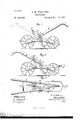
I attain these objects by means of the peculiar arrangement of the various parts of my device, which will be more fully pointed out and described inthe specification and claim, reference being had to the drawings accompanying this application and forming part of the same, in which- Figure vention, showing the handles turned to the front, by which the device is drawn by hand. Fig. 2 is a side view of the same, showing the handles reversed and clevis attached for animal-power. Fig. 3 is a top plan view, showing the parts in place.
Similar letters refer to similar parts through out the drawings. l
Referring to the drawings, A represents a. frame formed with an upward curve from each end, said ends being slotted and fitted with bearings for wheels, as shown. y
Handles B are secured to the front end of fra-me A by a bolt and nut, the outer ends of the same being formed in the usual manner.
Longitudinal slots are formed inhandles at a point near the center of the same, to receive clamp-bolts d, which are adapted to iit lnto notches cnt inbraces E, said braces being secured to the top of frame A, and extending upward and outward on the inside of handles B, near the slots in the same, as shown 1n Figs. l and 2. The purpose of this construction 1s to hold the handles B in a position to suit the operator. A short distance infront of said brace the frame A is perforated .to receive the 1 is a perspective view of my inplow-standard F, which is adjustable vertically in said perforation.
Secured to the outside of frame A, on either side of the same, are slotted curved guides D, adapted to receive a clamp-bolt passing through the handles B, by means of which said handles are adjusted to suit the operator when the handles are reversed wit-h their outer ends to the front, by which the cultivator is drawn by the operator when desired. Bolt AY is removed when the handles are reversed'and placed in the perforation in the opposite end of frame A. Said curved slotted guide-plates are secured to the outer face of frame A by means of a bolt passing through a perforation in a flange formed in the side of guide-plates.
A metal loop or clevis, C, having a perforation, f, at its outer end, by which power is attached, is attached by its inner ends to the sides of frame A by means of bolt bf.
. The operation of the device is as follows: When desired, an animal is attached to the outer end of clevis C; i The operator grasps the handles that are turned in position, as shown in Fig. 2. Vhen used as hand-power only, the operator grasps the handles that are in position shown in Fig. 1, when, by drawing the device along after him, the soil is looscned and the vegetables cultivated. When desired, the handles are reversed, and the operator, following inthe rear, grasps the handles and pushes the cultivator forward, the position of the operator in this case being at .times very important in cultivation of vegetables, frequently for the lack of room in having power attached to the front of the device. Having thus described my invention, what I claim, and desire to secure by Letters Patent,
In a two-wheeled cultivator, the combination of the curved frame A, the plow-standard F, the draw-clevis C, the forked brace E, hav ing notchesc, bolts d, e, and b, and the curved slotted guides D, secured to the sides of the frame A, with the reversible and adjustable handles B, substantially as shown and speciiied.
In testimony whereof I affix my signature in presence of two witnesses.
ROBERT M. WILLIAMS. Witnesses:
WM. H. Bron, G. P. WINDE.
Publications (1)
| Publication Number | Publication Date |
|---|---|
| US288288A true US288288A (en) | 1883-11-13 |
Family
ID=2357482
Family Applications (1)
| Application Number | Title | Priority Date | Filing Date |
|---|---|---|---|
| US288288D Expired - Lifetime US288288A (en) | williams |
Country Status (1)
| Country | Link |
|---|---|
| US (1) | US288288A (en) |
-
0
- US US288288D patent/US288288A/en not_active Expired - Lifetime
Similar Documents
| Publication | Publication Date | Title |
|---|---|---|
| US288288A (en) | williams | |
| US322975A (en) | Cotton chopper and cultivator | |
| US375647A (en) | Garden-plow | |
| US433373A (en) | schulz | |
| US148262A (en) | Improvement in cultivators | |
| US129894A (en) | Improvement in cultivators | |
| US176438A (en) | Improvement in cultivators | |
| US115138A (en) | Improvement in cultivators | |
| US222087A (en) | Improvement in combined horse-hoe and cultivator | |
| US131961A (en) | Improvement in plows | |
| US400837A (en) | Horace g | |
| US838477A (en) | Plow. | |
| US395784A (en) | Scraper and roller | |
| US417607A (en) | Cultivator | |
| US222275A (en) | Improvement in harrow attachments for corn-plows | |
| US59269A (en) | Improvement in cultivators | |
| US331913A (en) | Cultivator | |
| US391983A (en) | Hand-plow | |
| US295189A (en) | meadob | |
| US98650A (en) | Improvement in cultivators | |
| US552743A (en) | Cultivator | |
| US290142A (en) | thompson | |
| US681598A (en) | Plow. | |
| US338294A (en) | Cultivator | |
| US374469A (en) | Feancis c |