US2863243A - Easel mount with pocket and means for ejecting an insert therefrom - Google Patents
Easel mount with pocket and means for ejecting an insert therefrom Download PDFInfo
- Publication number
- US2863243A US2863243A US652450A US65245057A US2863243A US 2863243 A US2863243 A US 2863243A US 652450 A US652450 A US 652450A US 65245057 A US65245057 A US 65245057A US 2863243 A US2863243 A US 2863243A
- Authority
- US
- United States
- Prior art keywords
- ply
- opening
- leg
- insert
- Prior art date
- Legal status (The legal status is an assumption and is not a legal conclusion. Google has not performed a legal analysis and makes no representation as to the accuracy of the status listed.)
- Expired - Lifetime
Links
Images
Classifications
-
- A—HUMAN NECESSITIES
- A47—FURNITURE; DOMESTIC ARTICLES OR APPLIANCES; COFFEE MILLS; SPICE MILLS; SUCTION CLEANERS IN GENERAL
- A47G—HOUSEHOLD OR TABLE EQUIPMENT
- A47G1/00—Mirrors; Picture frames or the like, e.g. provided with heating, lighting or ventilating means
- A47G1/14—Photograph stands
- A47G1/141—Photograph stands made of sheet material
Definitions
- This invention relates to easel-type mounts such as are commonly employed for desk use to support an insert in the form of a calendar pad or photograph.
- a pocket is provided between the front and back plies for receiving the insert and the front ply has a window opening through it through which the insert may be seen.
- the pocket takes up the thickness of the insert so that its front face is fiush with or slightly behind the front face of the front ply, hence it is quite difficult to reach behind the insert particularly if it is close fitting, to removeit from the pocket when desired.
- the principal object of this invention is to provide a mount of the foregoing kind with means for displacing a part at least of the insert from the pocket through the window opening so that it may be readily grasped to withdraw the insert from the pocket.
- Other objects are to provide an ejection means which is of simple construction, easy to operate, does not require the addition of extraneous parts and is effective in operation.
- the mount comprises front, back and intermediate plies, thelatter being situated between and holding the front and back plies spaced so as to provide a pocket therebetween.
- the front ply has a window opening through it for admitting a pad to the pocket for exposure through the window.
- the back ply has an opening through it and a leg hinged thereto and there is connected to the leg a brace, one end of which is arranged to extend through the opening in the back ply into engagement with the tongue of the intermediate ply.
- the inner end of the tongue is operable by an application of pressure to the leg in a direction toward the back to displace the tongue forwardly, thereby to apply a thrust to the insert situated in the pocket which tends to disengage it from the pocket.
- the tongue may have an aperture in it and the inner end of the brace a nub for engagement within the aperture to hold the brace locked in position when the mount is set up.
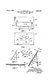
- Fig. 1 is a front elevation of the mount with the insert removed
- Fig. 2 is a rear elevation of the mount with the leg collapsed
- Fig. 3 is an end elevation of the mount in its set-up position
- Fig. 4 is a vertical section to larger scale of the mount set up showing the operation of the insert ejector
- Fig. 5 is a horizontal section taken on the line 5-5 of Fig. 4;
- Fig. 6 is a plan view of the intermediate spacer ply.
- the mount 16 as shown in 3, is comprised of an insert support 12, a leg 14 tinged therein, which swingable from a position in 2,863,243 Patepted Dec. 9, 1958 the plane of the back of the support rearwardly and a brace 16 hinged to the leg at one. end and swingable forwardly therefrom to dispose its other end in engagement with the backside of the support to hold the leg at an angle thereto.
- the support 12 as shown in Figs. 1 and 4, has a front ply 18 which is of substantially rectangular shape, through which there is a substantially rectangular opening in the form of a window having spaced parallel upper, and lower edges 20 and 22 and spaced parallel lateral edges 24-24.
- the support 12 also has a back ply 26 which is rectangular and as herein shown is coextensive with the front ply.
- the leg member 14 is cut out of the back ply along three sides 30 and 32-32" and is connected thereto at its fourth side by a hinge 34 formed, for example by scoring or in some other manner partially weakening the material of the ply along this side.
- the leg 14 may be swung rearwardly to an angular position with respect to the front ply so as to hold the support in an upright position, as shown for example in Figs. 3 and 4, or nested in the back ply.when the mount. is folded flat.
- the leg 14 may be made separate and fastened to the back ply by suitable means, for example, staples, however, if the leg is applied in this manner an opening must be provided in the back ply for purposes which will appear hereinafter,
- the leg 14] is held angularly disposed with reference to the front. ply by a brace 16 and this, as herein shown, is cut out of the leg itself along three sides 36 and 38-38 and is connected thereto at its fourth side by a hinge 40 formed by embossing or otherwise weakening the substance of the ply at that side.
- the front and back plies 18 and.26 are held in spaced parallel relation by an interposed intermediate ply 42 (Figs. 4 and 5), so as to provide between the front and rear plies a pocket 28. for receiving an insert.
- the intermediate ply 42 (Fig. 6) hasoutside dimensions which are coextensive with the front and back plies and an opening l lthrough it which is symmetrical with respect to the front opening andlhas a bottom edge 46 parallelling the bottom edge of the front opening, side edges 48 parallelling the side edges of. the front opening, and a top edge 5i parallelling the top edge of thefront opening.
- a tongue 52 projects downwardly from the top edge into the opening 44 so as to lie behind the. opening in the front ply and this tongue has three sides which lie within the boundaries of the front opening. Since the tongue is connected only along one side of the intermediate ply it may be deflected out of the plane of; the intermediate ply.
- the tongue 52 has in it an aperture 54. (Figs. 1 and 6) and the brace 16 has at its free end a nub 56 adapted to be engaged within the aperture 54 in the tongue. Ordinarily when the leg is pulled rearwardly to a position for setting up the mount the hub 56 is engaged within the aperture 54 to hold the leg locked in place.
- the mount is designed to hold an insert in the form of a calendar pad or photograph and the insert is placed in the pocket 28 between the front and back plies by sliding it through the front opening, the latter having, as shown in Fig. 1, awide mouth at its top and inwardly projecting keepers below the mouth which overlap the insert after it is placed within the pocket to hold it in place.
- the pocket has a front to back depth corresponding substantially to the thickness of the intermediate board, plus the thickness of the front ply, and hence when theinsert is seated in place its front surface is substantially flush with the front surface of the front ply or may lie somewhat inwardly thereof, so that it is quite dilficult if the lit is close to remove it, for example, if it is desirable to change the pad or substitute a different photograph.
- the use of a sharp instrument to get behind the insert is undesirable since it is apt to damage not only the insert but also the mount.
- the tongue 52 which extends into the pocket 28 from the intermediate ply provides means in combination with the brace 15 and leg 14 to thrust the insert from the pocket at least in part. This is effected by pressing the leg, as shown in Fig. 4, forwardly toward the back which in turn pushes the brace forwardly so that its forward end tends to deflect the tongue 52 forwardly with respect to the front opening, as shown in dot dash lines (Fig. 4). Forward deflection or bowing of the tongue 52 in turn thrusts theinsert p forwardly so as to disengage its 'upper edge from the upper or mouth portion of the pocket sufiiciently so that it may be grasped with the fingers and withdrawn from the pocket.
- the component parts of the mount as shown herein are comprised of stiff paperboard covered with decorative paper on the exposed surfaces and bound together at their lateral edges by folding portions of the decorative paper which is applied to the front ply over the edges and fastening them to the back ply.
- An easel-type mount comprising front, back and .intermediate plies, the latter being situated between and holding the front and back plies spaced so as to provide a pocket therebetween, said front ply having an opening through it defining a window at the front of the pocket, the lower and opposite sides of which overlap the pocket and the upper side of which coincides with the top of the pocket, so that an insert placed in the pocket is confined along its three sides and unconfined along the fourth side, said pocket being adapted to receive a flexible insert, a tongue extending from a portion of the intermediate ply into the pocket behind the i window opening, said back ply containing an opening through it behind the tongue, a leg hinged to the back ply, a brace connected to the leg at one end, said brace having another end arranged to be engaged with the tongue through said opening in the back ply and operable 'by pressure brought to bear on the leg in a direction to fold it to displace the tongue forwardly, relative to the plane of the pocket to displace the upper
- An easel-type mount comprising front, back and intermediate plies, the latter being situated between and holding the front and back plies spaced so as to provide a pocket therebetween, said front ply having an open ing through it defining a window at the front of the pocket, the lower and opposite sides of which overlap the pocket and the upper side of which coincides with the top of the pocket, so that an insert disposed in the pocket is confined along three sides, said intermediate ply havingran opening in it symmetrically located with reference to the window opening, from an edge of which a tongue'extends part way into the pocket behind the window opening, the edges of said tongue being spaced from the edges of the window opening, a leg cut out of the back ply along three sides and hinged thereto at the fourth so as to be swingable rearwardly therefrom to support the mount upright, and a brace connected at one end to the leg, the opposite end of the brace being adapted to be engaged with the tongue through the leg opening to hold the leg distended and being operable by pressure brought to bear on the
- An easel-type mount comprising front, back and intermediate plies, the latter being situated between and holding the front and back plies spaced so as to provide a pocket therebetween, said front ply having an opening through it defining an opening at the front of the pocket, the lower and opposite sides of which overlap the pocket and the upper side of which coincides with the top of the pocket, so that an insert disposed in the pocket is confined along three sides and unconfined along the fourth side, said intermediate ply having a partially separated portion behind the window opening which may be deflected out of the plane of the intermediate ply, said back ply having an opening through it, a leg hinged to the back ply, and a brace connected to the leg and having an end adapted to extend through the back ply opening into engagement with the partially separated portion of the intermediate ply, said leg being operable to displace the partially separated portion forwardly with reference to the window opening.
- An easel-type mount comprising front, back and intermediate plies, the latter being situated between and holding the front and back plies spaced so as to provide a pocket therebetween, said front ply having an opening through it defining a window at the front of the pocket, the lower and opposite sides of which overlap the pocket and the upper side of which coincides with the top of the pocket, so that an insert disposed in the pocket is confined along three sides and unconfined along the fourth side, said pocket being adapted to receive a flexible insert with its lower and opposite sides disposed behind the overlapping portion of the window and its upper side abutting the top of the pocket, said intermediate ply having a symmetrically located opening, from the upper edge of which a tongue projects downwardly into the pocket, its edges being spaced inwardly from the correspondingly located edges of the window opening, the back ply having an opening, a leg connected at one end to the back ply and a brace connected to the leg, and having an end adapted to extend through the back ply opening into engagement with the tongue
- An easel-type mount comprising front, back and intermediate plies, the latter being situated between and holding the front and back plies spaced apart so as to provide a pocket therebetween, said front ply having a substantially rectangular opening through it defining a window at the front of the pocket, the lower and opposite sides of which overlap the pocket and the upper side of which coincides with the top of the pocket so that an insert disposed within the pocket is confined along three sides and unconfined along the fourth side, a flexible insert disposed in the pocket with its lower and opposite sides situated behind the overlapping portion of the window and its upper side abutting the top of the pocket, said intermediate ply having a U-shaped opening through it symmetrically located with respect to the window, said opening running along the lower edge of the window opening and part way up the opposite side thereof, the part of the intermediate ply bounded by the opening being free to be deflected outwardly of the plane of the ply, said back ply having an opening through it to the back side of the pocket, a leg hinged to
- An easel-type mount comprising front, back and intermediate plies, the latter being situated between and holding the front and back plies spaced apart so as to provide a pocket therebetween, said front ply having a substantially rectangular opening through it defining a window at the front of the pocket, the lower and opposite sides of which overlap the pocket and the upper side of which coincides with the top of the pocket so that an insert disposed in the pocket is confined along its lower and opposite sides and unconfined along its top side, said intermediate ply having an opening through it symmetrically located with respect to the window in the front ply, a.
- An easel-type mount comprising a rigid body having an opening in its forward face behind which is a pocket having a yieldable bottom, the bottom and sides of which underlie the bottom and side edges of the window and the top of which coincides with the top of the window, said pocket being adapted to receive a flexible insert with the bottom and sides disposed behind the window opening in the portions of the pocket underlying the window opening and the top side abutting the top of the pocket, a leg hinged to the rear side of the body for disposition at an angle thereto, to support the body upright and a brace disposed between the leg and the yieldable bottom wall of the pocket for holding the leg at a rearwardly displaced angle to the body, said bottom wall normally resisting displacement and said leg being operable by movement toward the body to move the brace forwardly and hence to displace the yieldable bot tom of the pocket forwardly with respect to the window, and thereby to displace the top of the insert from the top of the pocket through the window opening.
Landscapes
- Details Of Garments (AREA)
Description
Dec. 9, 1958 G. E; NICHOLS 2,363,243
EASEL MOUNT WITH POCKET'AND MEANS FOR EJECTING AN INSERT THEREFROM Filed April 12, 1951 HIP aamzzfmzzfiak 16 PM #222 2" a EASEL l /lfl UN'll WHTH PQCKET AND MEANS FOR EJECTENG AN THEREFROM g Claims. (Cl. Ml-152.1)
This invention relates to easel-type mounts such as are commonly employed for desk use to support an insert in the form of a calendar pad or photograph.
in accordance with one kind of mount a pocket is provided between the front and back plies for receiving the insert and the front ply has a window opening through it through which the insert may be seen. The pocket takes up the thickness of the insert so that its front face is fiush with or slightly behind the front face of the front ply, hence it is quite difficult to reach behind the insert particularly if it is close fitting, to removeit from the pocket when desired. The principal object of this invention is to provide a mount of the foregoing kind with means for displacing a part at least of the insert from the pocket through the window opening so that it may be readily grasped to withdraw the insert from the pocket. Other objects are to provide an ejection means which is of simple construction, easy to operate, does not require the addition of extraneous parts and is effective in operation.
As herein illustrated the mount comprises front, back and intermediate plies, thelatter being situated between and holding the front and back plies spaced so as to provide a pocket therebetween. The front ply has a window opening through it for admitting a pad to the pocket for exposure through the window. Behind the window and extending downwardly into it from the intermediate ply there is a flexible tongue which may be displaced forwardly with respect to the intermediate ply and the window opening. The back ply has an opening through it and a leg hinged thereto and there is connected to the leg a brace, one end of which is arranged to extend through the opening in the back ply into engagement with the tongue of the intermediate ply. The inner end of the tongue is operable by an application of pressure to the leg in a direction toward the back to displace the tongue forwardly, thereby to apply a thrust to the insert situated in the pocket which tends to disengage it from the pocket. The tongue may have an aperture in it and the inner end of the brace a nub for engagement within the aperture to hold the brace locked in position when the mount is set up.
The invention will now be described in greater detail with reference to the accompanying drawings wherein:
Fig. 1 is a front elevation of the mount with the insert removed;
Fig. 2 is a rear elevation of the mount with the leg collapsed;
Fig. 3 is an end elevation of the mount in its set-up position;
Fig. 4 is a vertical section to larger scale of the mount set up showing the operation of the insert ejector;
Fig. 5 is a horizontal section taken on the line 5-5 of Fig. 4; and
Fig. 6 is a plan view of the intermediate spacer ply.
Referring to the figures, the mount 16, as shown in 3, is comprised of an insert support 12, a leg 14 tinged therein, which swingable from a position in 2,863,243 Patepted Dec. 9, 1958 the plane of the back of the support rearwardly and a brace 16 hinged to the leg at one. end and swingable forwardly therefrom to dispose its other end in engagement with the backside of the support to hold the leg at an angle thereto.
The support 12, as shown in Figs. 1 and 4, has a front ply 18 which is of substantially rectangular shape, through which there is a substantially rectangular opening in the form of a window having spaced parallel upper, and lower edges 20 and 22 and spaced parallel lateral edges 24-24.
The suport 12 also has a back ply 26 which is rectangular and as herein shown is coextensive with the front ply. The leg member 14 is cut out of the back ply along three sides 30 and 32-32" and is connected thereto at its fourth side by a hinge 34 formed, for example by scoring or in some other manner partially weakening the material of the ply along this side. As thus constructed the leg 14 may be swung rearwardly to an angular position with respect to the front ply so as to hold the support in an upright position, as shown for example in Figs. 3 and 4, or nested in the back ply.when the mount. is folded flat. If desired the leg 14 may be made separate and fastened to the back ply by suitable means, for example, staples, however, if the leg is applied in this manner an opening must be provided in the back ply for purposes which will appear hereinafter,
As previously pointed out, the leg 14] is held angularly disposed with reference to the front. ply by a brace 16 and this, as herein shown, is cut out of the leg itself along three sides 36 and 38-38 and is connected thereto at its fourth side by a hinge 40 formed by embossing or otherwise weakening the substance of the ply at that side.
The front and back plies 18 and.26 are held in spaced parallel relation by an interposed intermediate ply 42 (Figs. 4 and 5), so as to provide between the front and rear plies a pocket 28. for receiving an insert. The intermediate ply 42 (Fig. 6) hasoutside dimensions which are coextensive with the front and back plies and an opening l lthrough it which is symmetrical with respect to the front opening andlhas a bottom edge 46 parallelling the bottom edge of the front opening, side edges 48 parallelling the side edges of. the front opening, and a top edge 5i parallelling the top edge of thefront opening. A tongue 52 projects downwardly from the top edge into the opening 44 so as to lie behind the. opening in the front ply and this tongue has three sides which lie within the boundaries of the front opening. Since the tongue is connected only along one side of the intermediate ply it may be deflected out of the plane of; the intermediate ply.
The tongue 52 has in it an aperture 54. (Figs. 1 and 6) and the brace 16 has at its free end a nub 56 adapted to be engaged within the aperture 54 in the tongue. Ordinarily when the leg is pulled rearwardly to a position for setting up the mount the hub 56 is engaged within the aperture 54 to hold the leg locked in place.
As previously explained, the mount is designed to hold an insert in the form of a calendar pad or photograph and the insert is placed in the pocket 28 between the front and back plies by sliding it through the front opening, the latter having, as shown in Fig. 1, awide mouth at its top and inwardly projecting keepers below the mouth which overlap the insert after it is placed within the pocket to hold it in place. The pocket has a front to back depth corresponding substantially to the thickness of the intermediate board, plus the thickness of the front ply, and hence when theinsert is seated in place its front surface is substantially flush with the front surface of the front ply or may lie somewhat inwardly thereof, so that it is quite dilficult if the lit is close to remove it, for example, if it is desirable to change the pad or substitute a different photograph. The use of a sharp instrument to get behind the insert is undesirable since it is apt to damage not only the insert but also the mount. v
In accordance with this invention however the tongue 52 which extends into the pocket 28 from the intermediate ply provides means in combination with the brace 15 and leg 14 to thrust the insert from the pocket at least in part. This is effected by pressing the leg, as shown in Fig. 4, forwardly toward the back which in turn pushes the brace forwardly so that its forward end tends to deflect the tongue 52 forwardly with respect to the front opening, as shown in dot dash lines (Fig. 4). Forward deflection or bowing of the tongue 52 in turn thrusts theinsert p forwardly so as to disengage its 'upper edge from the upper or mouth portion of the pocket sufiiciently so that it may be grasped with the fingers and withdrawn from the pocket.
The component parts of the mount as shown herein are comprised of stiff paperboard covered with decorative paper on the exposed surfaces and bound together at their lateral edges by folding portions of the decorative paper which is applied to the front ply over the edges and fastening them to the back ply.
While the invention as herein illustrated is applied to an easel especially designed to receive and support a calendar pad it is, of course, to be understood that it is equally applicable to a mount for receiving a photograph in which case the window opening would be of much larger area.
It should be understood that the present disclosure is .for the purpose of illustration only and that this invention includes all modifications and equivalents which fall within the scope of the appended claims.
I claim:
1. An easel-type mount comprising front, back and .intermediate plies, the latter being situated between and holding the front and back plies spaced so as to provide a pocket therebetween, said front ply having an opening through it defining a window at the front of the pocket, the lower and opposite sides of which overlap the pocket and the upper side of which coincides with the top of the pocket, so that an insert placed in the pocket is confined along its three sides and unconfined along the fourth side, said pocket being adapted to receive a flexible insert, a tongue extending from a portion of the intermediate ply into the pocket behind the i window opening, said back ply containing an opening through it behind the tongue, a leg hinged to the back ply, a brace connected to the leg at one end, said brace having another end arranged to be engaged with the tongue through said opening in the back ply and operable 'by pressure brought to bear on the leg in a direction to fold it to displace the tongue forwardly, relative to the plane of the pocket to displace the upper edge of the insert occupying the pocket from the top of the pocket through the window opening.
2. An easel-type mount comprising front, back and intermediate plies, the latter being situated between and holding the front and back plies spaced so as to provide a pocket therebetween, said front ply having an open ing through it defining a window at the front of the pocket, the lower and opposite sides of which overlap the pocket and the upper side of which coincides with the top of the pocket, so that an insert disposed in the pocket is confined along three sides, said intermediate ply havingran opening in it symmetrically located with reference to the window opening, from an edge of which a tongue'extends part way into the pocket behind the window opening, the edges of said tongue being spaced from the edges of the window opening, a leg cut out of the back ply along three sides and hinged thereto at the fourth so as to be swingable rearwardly therefrom to support the mount upright, and a brace connected at one end to the leg, the opposite end of the brace being adapted to be engaged with the tongue through the leg opening to hold the leg distended and being operable by pressure brought to bear on the leg in a direction to restore the leg to the leg opening to displace the tongue forwardly in the direction of the window opening, thereby to displace the upper edge of the insert from beneath the top of the pocket.
3. An easel-type mount comprising front, back and intermediate plies, the latter being situated between and holding the front and back plies spaced so as to provide a pocket therebetween, said front ply having an opening through it defining an opening at the front of the pocket, the lower and opposite sides of which overlap the pocket and the upper side of which coincides with the top of the pocket, so that an insert disposed in the pocket is confined along three sides and unconfined along the fourth side, said intermediate ply having a partially separated portion behind the window opening which may be deflected out of the plane of the intermediate ply, said back ply having an opening through it, a leg hinged to the back ply, and a brace connected to the leg and having an end adapted to extend through the back ply opening into engagement with the partially separated portion of the intermediate ply, said leg being operable to displace the partially separated portion forwardly with reference to the window opening.
4. An easel-type mount comprising front, back and intermediate plies, the latter being situated between and holding the front and back plies spaced so as to provide a pocket therebetween, said front ply having an opening through it defining a window at the front of the pocket, the lower and opposite sides of which overlap the pocket and the upper side of which coincides with the top of the pocket, so that an insert disposed in the pocket is confined along three sides and unconfined along the fourth side, said pocket being adapted to receive a flexible insert with its lower and opposite sides disposed behind the overlapping portion of the window and its upper side abutting the top of the pocket, said intermediate ply having a symmetrically located opening, from the upper edge of which a tongue projects downwardly into the pocket, its edges being spaced inwardly from the correspondingly located edges of the window opening, the back ply having an opening, a leg connected at one end to the back ply and a brace connected to the leg, and having an end adapted to extend through the back ply opening into engagement with the tongue projecting downwardly from the intermediate ply, said brace being operable by pressure applied to the leg to thrust the tongue forwardly with respect to the window opening.
5. An easel-type mount comprising front, back and intermediate plies, the latter being situated between and holding the front and back plies spaced apart so as to provide a pocket therebetween, said front ply having a substantially rectangular opening through it defining a window at the front of the pocket, the lower and opposite sides of which overlap the pocket and the upper side of which coincides with the top of the pocket so that an insert disposed within the pocket is confined along three sides and unconfined along the fourth side, a flexible insert disposed in the pocket with its lower and opposite sides situated behind the overlapping portion of the window and its upper side abutting the top of the pocket, said intermediate ply having a U-shaped opening through it symmetrically located with respect to the window, said opening running along the lower edge of the window opening and part way up the opposite side thereof, the part of the intermediate ply bounded by the opening being free to be deflected outwardly of the plane of the ply, said back ply having an opening through it to the back side of the pocket, a leg hinged to the back ply, a brace connected at one end to the leg, the opposite end of the brace' being adapted to extend through the back opening into engagement with the deflectable portion of the intermediate ply and being operable by pressure applied to the leg to thrust the deflectable port1on forwardly with respect to the window opening.
6. An easel-type mount comprising front, back and intermediate plies, the latter being situated between and holding the front and back plies spaced apart so as to provide a pocket therebetween, said front ply having a substantially rectangular opening through it defining a window at the front of the pocket, the lower and opposite sides of which overlap the pocket and the upper side of which coincides with the top of the pocket so that an insert disposed in the pocket is confined along its lower and opposite sides and unconfined along its top side, said intermediate ply having an opening through it symmetrically located with respect to the window in the front ply, a. tongue projecting from the upper edge of the opening in the intermediate ply into the pocket behind the window opening, said tongue being connected to the intermediate ply but being free to be deflected out of the plane thereof, said back ply having an opening through it, a leg hinged to the back ply, and a brace hinged to the leg, said brace having an end adapted to extend through the back ply opening into engagement with the tongue and to be thrust therethrough sufliciently to bow the tongue outwardly.
7. An easel-type mount according to claim 6, wherein the tongue has an aperture through it and the brace has a nub sized to enter the aperture to lock the brace in position.
8. An easel-type mount comprising a rigid body having an opening in its forward face behind which is a pocket having a yieldable bottom, the bottom and sides of which underlie the bottom and side edges of the window and the top of which coincides with the top of the window, said pocket being adapted to receive a flexible insert with the bottom and sides disposed behind the window opening in the portions of the pocket underlying the window opening and the top side abutting the top of the pocket, a leg hinged to the rear side of the body for disposition at an angle thereto, to support the body upright and a brace disposed between the leg and the yieldable bottom wall of the pocket for holding the leg at a rearwardly displaced angle to the body, said bottom wall normally resisting displacement and said leg being operable by movement toward the body to move the brace forwardly and hence to displace the yieldable bot tom of the pocket forwardly with respect to the window, and thereby to displace the top of the insert from the top of the pocket through the window opening.
References Cited in the file of this patent UNITED STATES PATENTS 547,377 Gillbee Oct. 1, 1895 1,419,638 Miller June 13, 1922 2,062,916 Moore Dec. 1, 1936 2,477,886 McCaskill Aug. 2, 1949 2,651,867 Prew Sept. 15, 1953 2,787,853 Nichols Apr. 9, 1957
Priority Applications (1)
| Application Number | Priority Date | Filing Date | Title |
|---|---|---|---|
| US652450A US2863243A (en) | 1957-04-12 | 1957-04-12 | Easel mount with pocket and means for ejecting an insert therefrom |
Applications Claiming Priority (1)
| Application Number | Priority Date | Filing Date | Title |
|---|---|---|---|
| US652450A US2863243A (en) | 1957-04-12 | 1957-04-12 | Easel mount with pocket and means for ejecting an insert therefrom |
Publications (1)
| Publication Number | Publication Date |
|---|---|
| US2863243A true US2863243A (en) | 1958-12-09 |
Family
ID=24616875
Family Applications (1)
| Application Number | Title | Priority Date | Filing Date |
|---|---|---|---|
| US652450A Expired - Lifetime US2863243A (en) | 1957-04-12 | 1957-04-12 | Easel mount with pocket and means for ejecting an insert therefrom |
Country Status (1)
| Country | Link |
|---|---|
| US (1) | US2863243A (en) |
Cited By (8)
| Publication number | Priority date | Publication date | Assignee | Title |
|---|---|---|---|---|
| US2992631A (en) * | 1957-08-20 | 1961-07-18 | Lear Inc | Hydraulic stroke limiter |
| US3021631A (en) * | 1960-08-10 | 1962-02-20 | Carroll N Cross | Reinforced easel structure |
| US3244394A (en) * | 1963-08-19 | 1966-04-05 | Winthrop Atkins Co Inc | Mount for calendar pad, writing implements and materials |
| US3275280A (en) * | 1964-10-20 | 1966-09-27 | Winthrop Atkins Co Inc | Easel-type mount |
| US3275281A (en) * | 1965-01-12 | 1966-09-27 | Winthrop Atkins Co Inc | Easel structure |
| US3580536A (en) * | 1968-08-07 | 1971-05-25 | Winthrop Atkins Co Inc | Slant front easel |
| US20040046097A1 (en) * | 2001-11-06 | 2004-03-11 | Stearns Laura L. | Pocketed easel back counter card |
| US20240237836A1 (en) * | 2023-01-18 | 2024-07-18 | Andrea Bevell | Decorative gift display device |
Citations (6)
| Publication number | Priority date | Publication date | Assignee | Title |
|---|---|---|---|---|
| US547377A (en) * | 1895-10-01 | Easel picture-frame | ||
| US1419638A (en) * | 1921-08-16 | 1922-06-13 | Max V Miller | Display device and blank |
| US2062916A (en) * | 1936-04-17 | 1936-12-01 | Howard L Moore | Combined holder and display stand |
| US2477886A (en) * | 1945-11-20 | 1949-08-02 | Oscar E Mccaskill | Stock sheet for postage stamps |
| US2651867A (en) * | 1950-09-01 | 1953-09-15 | Pru Lesco Inc | Picture frame holder |
| US2787853A (en) * | 1952-01-26 | 1957-04-09 | Winthrop Atkins Co Inc | Display mount having corner pockets |
-
1957
- 1957-04-12 US US652450A patent/US2863243A/en not_active Expired - Lifetime
Patent Citations (6)
| Publication number | Priority date | Publication date | Assignee | Title |
|---|---|---|---|---|
| US547377A (en) * | 1895-10-01 | Easel picture-frame | ||
| US1419638A (en) * | 1921-08-16 | 1922-06-13 | Max V Miller | Display device and blank |
| US2062916A (en) * | 1936-04-17 | 1936-12-01 | Howard L Moore | Combined holder and display stand |
| US2477886A (en) * | 1945-11-20 | 1949-08-02 | Oscar E Mccaskill | Stock sheet for postage stamps |
| US2651867A (en) * | 1950-09-01 | 1953-09-15 | Pru Lesco Inc | Picture frame holder |
| US2787853A (en) * | 1952-01-26 | 1957-04-09 | Winthrop Atkins Co Inc | Display mount having corner pockets |
Cited By (8)
| Publication number | Priority date | Publication date | Assignee | Title |
|---|---|---|---|---|
| US2992631A (en) * | 1957-08-20 | 1961-07-18 | Lear Inc | Hydraulic stroke limiter |
| US3021631A (en) * | 1960-08-10 | 1962-02-20 | Carroll N Cross | Reinforced easel structure |
| US3244394A (en) * | 1963-08-19 | 1966-04-05 | Winthrop Atkins Co Inc | Mount for calendar pad, writing implements and materials |
| US3275280A (en) * | 1964-10-20 | 1966-09-27 | Winthrop Atkins Co Inc | Easel-type mount |
| US3275281A (en) * | 1965-01-12 | 1966-09-27 | Winthrop Atkins Co Inc | Easel structure |
| US3580536A (en) * | 1968-08-07 | 1971-05-25 | Winthrop Atkins Co Inc | Slant front easel |
| US20040046097A1 (en) * | 2001-11-06 | 2004-03-11 | Stearns Laura L. | Pocketed easel back counter card |
| US20240237836A1 (en) * | 2023-01-18 | 2024-07-18 | Andrea Bevell | Decorative gift display device |
Similar Documents
| Publication | Publication Date | Title |
|---|---|---|
| US1901243A (en) | Dispenser | |
| US2863243A (en) | Easel mount with pocket and means for ejecting an insert therefrom | |
| US2443645A (en) | Picture frame and support | |
| US4442617A (en) | Photographic print display device | |
| US2450495A (en) | Easel | |
| US1486652A (en) | Combined photograph folder and easel | |
| US2031575A (en) | Folding box | |
| US1893624A (en) | Container and supporting unit | |
| NO793003L (en) | SALES PACKAGING OF THE ADVERTISING TYPE. | |
| US1359662A (en) | Easel | |
| US2630641A (en) | Combined easel and scroll sign | |
| US2160164A (en) | Container | |
| US2946545A (en) | Calendar mount or the like | |
| US2049165A (en) | Photo mount | |
| US2508854A (en) | Stamp mount | |
| US2322259A (en) | Line indicating copyholder | |
| US2519261A (en) | Tissue container | |
| US537613A (en) | Case for toilet-paper | |
| US2976631A (en) | Display mounts for calendar pads or the like | |
| US2203474A (en) | Compartment drawing board | |
| US3580536A (en) | Slant front easel | |
| US2526765A (en) | Leg and brace unit for easels | |
| US1710814A (en) | Easel attachment | |
| US700256A (en) | Fastener for backings in picture-frames. | |
| US2114528A (en) | Display easel |