US2861925A - High vacuum distillation apparatus - Google Patents
High vacuum distillation apparatus Download PDFInfo
- Publication number
- US2861925A US2861925A US581742A US58174256A US2861925A US 2861925 A US2861925 A US 2861925A US 581742 A US581742 A US 581742A US 58174256 A US58174256 A US 58174256A US 2861925 A US2861925 A US 2861925A
- Authority
- US
- United States
- Prior art keywords
- discs
- disc
- distillate
- shaft
- container
- Prior art date
- Legal status (The legal status is an assumption and is not a legal conclusion. Google has not performed a legal analysis and makes no representation as to the accuracy of the status listed.)
- Expired - Lifetime
Links
- 238000005292 vacuum distillation Methods 0.000 title description 7
- 238000001704 evaporation Methods 0.000 description 12
- 239000007788 liquid Substances 0.000 description 12
- 238000001816 cooling Methods 0.000 description 10
- 238000010438 heat treatment Methods 0.000 description 10
- 238000004821 distillation Methods 0.000 description 6
- 230000008020 evaporation Effects 0.000 description 6
- 239000012530 fluid Substances 0.000 description 5
- 238000005192 partition Methods 0.000 description 5
- 239000000126 substance Substances 0.000 description 5
- 239000003795 chemical substances by application Substances 0.000 description 4
- 238000009833 condensation Methods 0.000 description 4
- 230000005494 condensation Effects 0.000 description 4
- 239000000203 mixture Substances 0.000 description 4
- 239000002826 coolant Substances 0.000 description 3
- 238000000199 molecular distillation Methods 0.000 description 3
- 241000196324 Embryophyta Species 0.000 description 2
- 230000009471 action Effects 0.000 description 2
- 238000000034 method Methods 0.000 description 2
- 230000008569 process Effects 0.000 description 2
- 238000005086 pumping Methods 0.000 description 2
- PZASAAIJIFDWSB-CKPDSHCKSA-N 8-[(1S)-1-[8-(trifluoromethyl)-7-[4-(trifluoromethyl)cyclohexyl]oxynaphthalen-2-yl]ethyl]-8-azabicyclo[3.2.1]octane-3-carboxylic acid Chemical compound FC(F)(F)C=1C2=CC([C@@H](N3C4CCC3CC(C4)C(O)=O)C)=CC=C2C=CC=1OC1CCC(C(F)(F)F)CC1 PZASAAIJIFDWSB-CKPDSHCKSA-N 0.000 description 1
- 102000004405 Collectins Human genes 0.000 description 1
- 108090000909 Collectins Proteins 0.000 description 1
- 240000006829 Ficus sundaica Species 0.000 description 1
- 229910000831 Steel Inorganic materials 0.000 description 1
- 238000009835 boiling Methods 0.000 description 1
- 239000000919 ceramic Substances 0.000 description 1
- 238000001944 continuous distillation Methods 0.000 description 1
- 238000000354 decomposition reaction Methods 0.000 description 1
- 238000009792 diffusion process Methods 0.000 description 1
- 238000007598 dipping method Methods 0.000 description 1
- 238000006073 displacement reaction Methods 0.000 description 1
- 238000005485 electric heating Methods 0.000 description 1
- 238000005194 fractionation Methods 0.000 description 1
- 238000009413 insulation Methods 0.000 description 1
- 238000002156 mixing Methods 0.000 description 1
- 229910052759 nickel Inorganic materials 0.000 description 1
- PXHVJJICTQNCMI-UHFFFAOYSA-N nickel Substances [Ni] PXHVJJICTQNCMI-UHFFFAOYSA-N 0.000 description 1
- 230000009467 reduction Effects 0.000 description 1
- 238000000926 separation method Methods 0.000 description 1
- 239000010959 steel Substances 0.000 description 1
- 238000011144 upstream manufacturing Methods 0.000 description 1
Images

Classifications
-
- B—PERFORMING OPERATIONS; TRANSPORTING
- B01—PHYSICAL OR CHEMICAL PROCESSES OR APPARATUS IN GENERAL
- B01D—SEPARATION
- B01D3/00—Distillation or related exchange processes in which liquids are contacted with gaseous media, e.g. stripping
- B01D3/12—Molecular distillation
Definitions
- the present invention relates to high vacuum distillation apparatus-particularly to apparatus for carrying out molecular distillations in which the distance between the evaporation surface and the condensation surface is smaller than the mean free path of the vapor molecules.
- the invention is concerned with improvements of high vacuum distillation apparatusof the type in which a rotating horizontal shaft is provided inside a vacuum container, a plurality of discs being mounted on the shaft in spaced relation and at a right angle to the rotation axis of the shaft.
- the discs are at least partly heated to different temperatures and are partly immersed in the liquid to be distilled which is at the bottom or sump of the vacuum container for picking up the liquid upon rotation of the discs.
- the lateral surfaces of the discs form evaporation surfaces which are individually opposed to stationary condensation surfaces.
- the latter are formed by the lateral walls of pockets which are individually interposed between the aforesaid discs, a coolant flowing through the interior of the pockets.
- Means are provided for continuously supplyingthe substance to be distilled into the container and for removing the distillation residues from the container.
- the invention is characterized by the provision of two troughs beneath the cooling pockets which are interposed between ditferently heated discs for individually receiving the distillate dripping from the lateral walls of the pockets.
- Preferably separate collecting and removing conduits are provided for the distillate collected in the individual troughs. In some cases it may be advisable to provide a single collecting conduit for the distillate received in two troughs from distilland evaporated on'the two sides of the same disc.
- additional walls may be provided which walls envelop the marginal portions of the discs and form with the latter a cleaiance or gap, the additional walls and the separating walls dividing the spaces in the sump of the container between the discs into individual chambers.
- Fig. l is a schematic longitudinal sectional illustration of an apparatus according to the invention for molecular distillation
- Fig. 2 is a cross sectional view of the apparatus shown in Fig. 1, the section being taken along line IIII in Fig. l;
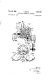
- FIG. 3 is a cross sectional view along line III--III of the lower part of the apparatus shown, inFig. 1; r
- Fig. 4 is a cross sectional viewofa modified detailof tbs appa atus h WniuFig- 1,- i fi Patented Nov. 25, 1958
- Fig. 5 is a sectional view of the detail shown in Fig; 4, the section being taken along line V-V in Fig. 4;
- Fig. 6 is a large scale sectional view of an evaporating disc
- Fig. 7 is a large scale sectional view of a modified evaporating disc
- Fig. 8 is a diagrammatic longitudinal sectional view of a modified apparatus according to the invention.
- Substances having a high boiling point can be decomposed by high vacuum distillation at temperatures which are below the decomposition point of the substances.
- inolecular distillation distillation is eifected at such a vacuum that the length of the mean free path of the vapor molecules is' greater than the distance between the evaporation surface and the condensation surface. These processes are based on the consideration that the maximal possible distillation velocity can be obtained, if provisions are made ensuring that each molecule leaving the evaporation surface reaches the condensation surface and is held thereat without bouncing into other molecules in the vapor space.
- Figs. 1 and 2 illustrate an apparatus which is suitable for performing molecular distillation.
- a vacuum container including a horizontal cylindrical vessel 1 and a removable cover 2 is connected by a pipe 3 with a conventional vacuum pumping plant, not shown.
- the latter usually includes a diffusion pump upstream of which is a pre-vacuum pump and which must be adapted to maintain very low pressures, as a rule less than 10- mm. Hg, within the vacuum container.
- the pipe 3 may be cooled by a cooler 4 so that vapors in the pipe 3 are condensed and prevented to enter the vacuum pumping plant.
- a pipe 5 terminates in the lower part of the vacuum container which will henceforth be called the sump.
- the pipe 5 which is provided with a valve 7 connects theinterior of the vacuum container with a reservo-ir 6 for the liquid to be distilled; the latter will henceforth be called distilland.
- a discharge conduit for the distillation residues is vertically movable in a stufling box 41 and terminates in a flask 42.
- a hollow shaft 8 having one end rotating in a bearof the shaft 8 extends through 1 to the outside, a stuffing box preventing entry of air into the vacuum container.
- the shaft 8 can be rotated by driv ing a drive wheel 11 mounted on the shaft 8 by conventional means, notshown.
- a plurality of hollow discs 12a, 12b, are mounted in spaced relation on the shaft 8, the discs being partly immersed in the distilland in the sump of the vacuum container.
- the discs 12 are provided with scoops 43.
- a heating liquid is pumped by a gear pump 16 from a the wall of the vessel 10 being provided for 13 located inside the hollow shaft 8.
- the liquid in the reservoir 15 is heated by a heater 17 to a desired temperature.
- the heating liquid enters the space between the pipe 13 and the hollow shaft 8through apertures 18 in the right end of the pipe and flows into the interior of the hollow discs 12. Batfles 19 inside the discs 12 force the heating liquid to flow along the insides of the lateral walls of the discs 12.
- the heating liquid flows consecutively through the discs 12c, 12b, 12a and is returned to the reservoir 15 through a conduit 20.
- Stationary cooling pockets 22, 23, 24, and 25 are interposed between and on the outside of the outermostevaporation discs 12. .A coolant-is conducted to the pockets the right side of 22 t 2.5. ro gh. a. condui 2 n r m ve ther f om. through a conduit 27.
- the lower marginal portion of the pockets 22 and 25 is wedge shaped and extends into troughs 28 and 29, respectively, for catching the condensate formed on the sunfaces of the pockets 22 and 25 which; surfaces faceithediscs 12a and 120, respectively.
- the pockets 23 and 24 which are interposed between the discs 12a, 12b and 12b, 12c, respectively, are provided with two spaced edges at their lower ends so that the, distillate condensed at the two sides of thepockets is not mixed,
- a separate trough is provided for each edge, the troughs forthe pocket 23 being designated by numerals 30 and 31 and the troughs for the two edges of the pocket 24- being designated by numerals 32 and 33.
- the troughs have a relatively high elevation at the center and a lowest point at either end. These lowest; points; are connected with, distillate collecting conduits; The distillate caught in the trough, 29 which distillate comes from the side of the pocket 25 facing the disc 12c flows through.
- conduits 29a and 2% into a collecting tube 39.
- the condensate collected in the troughs or drip trays 28, 30, 31, 32, and 33 flows into collecting conduits 34, 35, 36, 37, and 38, respectively.
- the conduits 34 to 39 extend through the cover 2 tothe outside and terminate in flasks 40a, 40b, .0. 4 d. 4 a v 1
- the apparatus operates as follows: Upon rotation of the shaft 8 a layer or-filrn of liquid is formed on the discs 12a, 12b, and 12c which. are partly immersed in the distilland; this action is assisted by the scoops 43 which are arranged at the marginal portions of the discs. The sides of the latter act as evaporation surfaces. The vapor molecules released from the liquid film are caught by thetside surfaces of the cooling pockets 22 to 25 which are opposed to the respective sides of the discs. The condensate flows into the drip trays and therefrom through the collecting conduits into the respective flasks.
- the arrangement of the drip trays and connecting and collecting conduits according to the invention affords increased selectivity and differentiated action of the disc stages. Due to the reduction of the temperature of the heating agent while it consecutively flows through the individual evaporation discs the average temperatures of the lateralsurfaces of thediscs become lower and lower as they are heated by the flowing and cooling heating agent The distilland flows consecutively through the spaces formed by the discs. in the sump.
- the disc 12a scoops distilland which spreads over the lateral surfaces of thedisc.
- the temperature of the left side of the disc 12a is lower than that of the right side. Therefore, the most volatile substances contained in the distilland evaprate at: the left side of the disc 12a.
- the liquid film on the right side of the disc 12a is formed of somewhat less volatile substances whereby the percentage of the less volatile portion of the distilland to be evaporated on the disc 12a. is increased.
- The-liquid filrn on the. right. side of the disc contains less volatile substancesthan thematter evaporated at the'left sideof the disc.v Dueto; the separate removal of the distillate COIldtiDSdClQOll-thfi! pocket 22 and on the left side of thepocket 23, a continuous distillation can be performed at a highly selective fractionation.
- FIG. 6 illustrates a structurein whichdnstead of a central baflie 19a hollow body 47 is arranged the-interior of which communicates with the hollow; shaft8.
- distillate collected in two, drip; trays, for example 28 and-.30 in Fig. 1, and resulting from vapor produced on the side surfacesof the same disc, for example 12a. Since the temperature of both side surfaces is the same, the distillate collected in both trays is the same.
- the discs may be heated electrically instead of by means of a heating fluid and means may be provided for heating both sides of the. discs to the. same temperature.
- FIG. 7 and 8 An apparatus of this type is shown in Figs. 7 and 8 in which numeral 51 designates a disc corresponding to one of the discs 12 in Fig. 1.
- the disc 51 includes two disc shaped ceramic insulation elements 54 and 55, the latter being provided with a spiral groove 56 into which an electric heating wire 57 is placed.
- the elements 54 and 55 are encased in an envelope 52 made of stainless chrome-nickel steel and mounted on a hollow shaft 53 which projects from a vacuum container 65 as does the shaft 8 project fro-m the container 1 in Fig. 1.
- the ends of the wire 57 are connected with wires 58 and 59 which are enclosed in insulating tubes, 60.
- the free ends of the wires 58 and 59 are connected with a contact ring 61 and a contact plate 62, respectively.
- the elements 61 and 62 are mounted on one end face of the shaft 53 and are electrically insulated therefrom. Current is supplied to the elements 61 and 62 in the conventional manner.
- Fig. 8 shows an apparatus in which discs a, b,- c, d, e, and f of the type shown in Fig. 7 are mounted on a shaft 66.
- the discs dip into the distilland in the bottom, of the container 65. Cooling pocketsm, n, 0, p, q, r, and s are individually interposed between the discs.
- the temperature. of the discs a, b, c is maintained the same and the temperature of the discs 11, e, f is held higher than that of. the discs 4 b, C, the temperature of the disc 2 being higher than that of disc d' and the temperature of the disc fbeing higher than that ofthe disc 0.
- the temperatures of both side walls of eachldisc. are the same. Since the side walls of the discs at, b, and 0 have the same temperature, the distillate collected in the trays m, nT, and 0' which are beneath the pockets m, n, and o has. the same composition and can be removed in a common collecting pipe 67.
- The. composition of the. distillate condensed on the left side of the pocket p and collected. in the tray .p' is the same as that collected in the trays m, n,, and 0 and can also be conducted into the pipe. 67.
- the distillate evaporated on the sides of the disc d which is condensed on the right side of the. poclget. p.
- Fig. 8 is diagrammatic and the means for supplying a coolant into the-pockets. m, n, 0, p, q, r, and s are not shown. They are the same as the coolant supply means 26, 27 in Fig. 1.
- partitions 44 are arranged. in the sump of the vacuum container between two consecutive discs 12 so that the sump is subdivided into individual chambers for the individual discs.
- the partitions form an overflow between the individual chambers.
- Each individual'chamber formed by the partitions 44 is further'divided by a. separating wall 45 so that there is a sub-chamber for: each side surface of each disc 12.
- the walls 45 (Figs; 4* and 5 extend to the circumference of the discs 12, leaving only a small clearance, throttling the flow of the distilland as the distillandpasses through the sump of the vacuum container.
- the cooling pockets and the drip trays are not shown in Figs. 3 and 4.
- the arrangement of the partitions 44 and of the separating walls 45 increase the degree of separation and the distillation velocity.
- An apparatus for distilling at a high vacuum comprising, in combination, a vacuum container, a horizontal shaft rotatable in said container, a plurality of discs mounted on said shaft and having side surfaces placed at a right angle to said shaft, means connected with said discs for heating same to different temperatures, said container having a bottom portion, means for supplying the fluid to be distilled into said bottom portion, said discs dipping into the fluid in said bottom portion and picking up fluid upon rotation of said shaft for evaporating part of the fluid from said side surfaces, a plurality of cooling means individually having side surfaces individually placed opposite individual side surfaces of said discs for condensing the part of the fiuid evaporating from the side surfaces of said discs on the opposed side surfaces 20 of said cooling means, a separate trough placed beneath each of the side surfaces of those of said cooling means whose side surfaces are placed between two neighboring discs for separately collecting the distillate dripping from the side surfaces of the cooling means which side surfaces are located opposite the neighboring side surfaces of two different discs, and partitions
Landscapes
- Chemical & Material Sciences (AREA)
- Chemical Kinetics & Catalysis (AREA)
- Vaporization, Distillation, Condensation, Sublimation, And Cold Traps (AREA)
Applications Claiming Priority (1)
| Application Number | Priority Date | Filing Date | Title |
|---|---|---|---|
| CH798072X | 1955-05-02 |
Publications (1)
| Publication Number | Publication Date |
|---|---|
| US2861925A true US2861925A (en) | 1958-11-25 |
Family
ID=4537448
Family Applications (1)
| Application Number | Title | Priority Date | Filing Date |
|---|---|---|---|
| US581742A Expired - Lifetime US2861925A (en) | 1955-05-02 | 1956-04-30 | High vacuum distillation apparatus |
Country Status (6)
| Country | Link |
|---|---|
| US (1) | US2861925A (cs) |
| CH (1) | CH332797A (cs) |
| DE (1) | DE956666C (cs) |
| FR (1) | FR1149582A (cs) |
| GB (1) | GB798072A (cs) |
| NL (2) | NL197445A (cs) |
Cited By (3)
| Publication number | Priority date | Publication date | Assignee | Title |
|---|---|---|---|---|
| US3196087A (en) * | 1961-03-28 | 1965-07-20 | Gen Electric | Water demineralizing apparatus |
| US3330739A (en) * | 1964-06-05 | 1967-07-11 | Saline Water Conversion Corp | Multi-cell flash distillation system |
| US4504361A (en) * | 1981-06-22 | 1985-03-12 | Slovenska Vysoka Skola Technicka V Bratislava | Block short-way evaporator with wiped-off film |
Citations (1)
| Publication number | Priority date | Publication date | Assignee | Title |
|---|---|---|---|---|
| US2703310A (en) * | 1953-12-03 | 1955-03-01 | Givaudan Corp | Apparatus for molecular distillation |
-
0
- NL NL91538D patent/NL91538C/xx active
- NL NL197445D patent/NL197445A/xx unknown
-
1955
- 1955-05-02 CH CH332797D patent/CH332797A/de unknown
- 1955-05-10 DE DES43861A patent/DE956666C/de not_active Expired
-
1956
- 1956-04-24 FR FR1149582D patent/FR1149582A/fr not_active Expired
- 1956-04-30 US US581742A patent/US2861925A/en not_active Expired - Lifetime
- 1956-05-01 GB GB13439/56A patent/GB798072A/en not_active Expired
Patent Citations (1)
| Publication number | Priority date | Publication date | Assignee | Title |
|---|---|---|---|---|
| US2703310A (en) * | 1953-12-03 | 1955-03-01 | Givaudan Corp | Apparatus for molecular distillation |
Cited By (3)
| Publication number | Priority date | Publication date | Assignee | Title |
|---|---|---|---|---|
| US3196087A (en) * | 1961-03-28 | 1965-07-20 | Gen Electric | Water demineralizing apparatus |
| US3330739A (en) * | 1964-06-05 | 1967-07-11 | Saline Water Conversion Corp | Multi-cell flash distillation system |
| US4504361A (en) * | 1981-06-22 | 1985-03-12 | Slovenska Vysoka Skola Technicka V Bratislava | Block short-way evaporator with wiped-off film |
Also Published As
| Publication number | Publication date |
|---|---|
| CH332797A (de) | 1958-09-30 |
| NL197445A (cs) | |
| DE956666C (de) | 1957-01-24 |
| GB798072A (en) | 1958-07-16 |
| NL91538C (cs) | |
| FR1149582A (fr) | 1957-12-27 |
Similar Documents
| Publication | Publication Date | Title |
|---|---|---|
| US2703310A (en) | Apparatus for molecular distillation | |
| GB1021569A (en) | Flash evaporators | |
| US3250687A (en) | Apparatus with ground glass surface for film-type distillation | |
| US20180117493A1 (en) | Evaporator | |
| US2514944A (en) | Falling film distillation apparatus | |
| US2861925A (en) | High vacuum distillation apparatus | |
| US3789579A (en) | Removal of air and water from oil | |
| US2584785A (en) | Process and apparatus for separation of mixtures | |
| US2890155A (en) | Method and apparatus for the fractional distillation of multicomponent mixtures | |
| US2126467A (en) | Distillation process | |
| GB1433451A (en) | Gas-liquid contact apparatus for effecting heat-and mass transfer between fluids | |
| KR0161518B1 (ko) | 인취장치 | |
| US2766193A (en) | Apparatus for distilling or evaporating liquids | |
| US1955321A (en) | Vacuum distillation | |
| Biehler et al. | Small laboratory centrifugal molecular still | |
| US3214350A (en) | Falling film still | |
| US2782843A (en) | Apparatus for continuous removal of volatile materials from liquids | |
| US3123083A (en) | Metal degreasing apparatus | |
| EP0268583A1 (en) | DEVICE AND DISTILLATION METHOD. | |
| US2647862A (en) | Process and apparatus for vacuum distillation | |
| US1327599A (en) | Apparatus for cooling and scrubbing gases | |
| US2284623A (en) | Vaporizer | |
| US2077645A (en) | Tray structure for bubble towers | |
| US1449313A (en) | Distilling apparatus | |
| US575854A (en) | scott |