US2846793A - Smoothing iron soleplate - Google Patents
Smoothing iron soleplate Download PDFInfo
- Publication number
- US2846793A US2846793A US502764A US50276455A US2846793A US 2846793 A US2846793 A US 2846793A US 502764 A US502764 A US 502764A US 50276455 A US50276455 A US 50276455A US 2846793 A US2846793 A US 2846793A
- Authority
- US
- United States
- Prior art keywords
- soleplate
- shoe
- smoothing
- body portion
- steam
- Prior art date
- Legal status (The legal status is an assumption and is not a legal conclusion. Google has not performed a legal analysis and makes no representation as to the accuracy of the status listed.)
- Expired - Lifetime
Links
- 238000009499 grossing Methods 0.000 title description 39
- XEEYBQQBJWHFJM-UHFFFAOYSA-N Iron Chemical compound [Fe] XEEYBQQBJWHFJM-UHFFFAOYSA-N 0.000 title description 22
- 229910052742 iron Inorganic materials 0.000 title description 11
- 238000005260 corrosion Methods 0.000 description 16
- 230000007797 corrosion Effects 0.000 description 15
- 229910052782 aluminium Inorganic materials 0.000 description 14
- XAGFODPZIPBFFR-UHFFFAOYSA-N aluminium Chemical compound [Al] XAGFODPZIPBFFR-UHFFFAOYSA-N 0.000 description 14
- 235000000396 iron Nutrition 0.000 description 13
- 238000005299 abrasion Methods 0.000 description 11
- PXHVJJICTQNCMI-UHFFFAOYSA-N Nickel Chemical compound [Ni] PXHVJJICTQNCMI-UHFFFAOYSA-N 0.000 description 10
- 238000010438 heat treatment Methods 0.000 description 8
- 239000000463 material Substances 0.000 description 8
- 239000002131 composite material Substances 0.000 description 7
- 229910052751 metal Inorganic materials 0.000 description 7
- 239000002184 metal Substances 0.000 description 7
- VYZAMTAEIAYCRO-UHFFFAOYSA-N Chromium Chemical compound [Cr] VYZAMTAEIAYCRO-UHFFFAOYSA-N 0.000 description 6
- 238000010276 construction Methods 0.000 description 6
- 238000004519 manufacturing process Methods 0.000 description 5
- 238000000034 method Methods 0.000 description 5
- 229910052759 nickel Inorganic materials 0.000 description 5
- 230000015572 biosynthetic process Effects 0.000 description 4
- 229910000831 Steel Inorganic materials 0.000 description 3
- 238000005266 casting Methods 0.000 description 3
- 238000003801 milling Methods 0.000 description 3
- 230000035939 shock Effects 0.000 description 3
- 239000010959 steel Substances 0.000 description 3
- 229910001369 Brass Inorganic materials 0.000 description 2
- 239000010951 brass Substances 0.000 description 2
- 239000010962 carbon steel Substances 0.000 description 2
- 238000002845 discoloration Methods 0.000 description 2
- 230000004048 modification Effects 0.000 description 2
- 238000012986 modification Methods 0.000 description 2
- 230000009972 noncorrosive effect Effects 0.000 description 2
- 229910000975 Carbon steel Inorganic materials 0.000 description 1
- 229910000881 Cu alloy Inorganic materials 0.000 description 1
- WPPDFTBPZNZZRP-UHFFFAOYSA-N aluminum copper Chemical compound [Al].[Cu] WPPDFTBPZNZZRP-UHFFFAOYSA-N 0.000 description 1
- 238000005219 brazing Methods 0.000 description 1
- 230000000295 complement effect Effects 0.000 description 1
- 238000005520 cutting process Methods 0.000 description 1
- 238000004512 die casting Methods 0.000 description 1
- 238000009826 distribution Methods 0.000 description 1
- 238000005553 drilling Methods 0.000 description 1
- 210000005069 ears Anatomy 0.000 description 1
- 230000002708 enhancing effect Effects 0.000 description 1
- 238000000227 grinding Methods 0.000 description 1
- 229910021385 hard carbon Inorganic materials 0.000 description 1
- 230000013011 mating Effects 0.000 description 1
- 230000002093 peripheral effect Effects 0.000 description 1
- 238000007747 plating Methods 0.000 description 1
- 238000003825 pressing Methods 0.000 description 1
- 238000006748 scratching Methods 0.000 description 1
- 230000002393 scratching effect Effects 0.000 description 1
- 239000007787 solid Substances 0.000 description 1
- XLYOFNOQVPJJNP-UHFFFAOYSA-N water Substances O XLYOFNOQVPJJNP-UHFFFAOYSA-N 0.000 description 1
- 238000003466 welding Methods 0.000 description 1
Images


Classifications
-
- D—TEXTILES; PAPER
- D06—TREATMENT OF TEXTILES OR THE LIKE; LAUNDERING; FLEXIBLE MATERIALS NOT OTHERWISE PROVIDED FOR
- D06F—LAUNDERING, DRYING, IRONING, PRESSING OR FOLDING TEXTILE ARTICLES
- D06F75/00—Hand irons
- D06F75/38—Sole plates
Definitions
- the instant invention relates to the manufacture of soleplates for smoothing irons and more particularly to a novel composite soleplate for such irons and the process of manufacturing such soleplates.
- Smoothing irons generally comprise an electrically heated soleplate formed with a smoothing surface, the soleplate including an embedded electrical heating element, usually of a rod type, for heating the smoothing surface.
- the embedded heating element also serves to supply heat to a boiler for the generation of steam therein.
- An aluminum sole plate is very desirable because of the feature of high thermal conductivity as well as light weight, pleasing appearance and high corrosion resistance.
- Such sole plates may be polished to enhance the appearance thereof; however, the sole plates constructed of aluminum do not possess a high resistance to abrasion and are subject to scratching and discoloration so that after continued use, the smoothing surface of the sole plate will present an unpleasing appearance to user.
- the soleplate of the smoothing iron is formed of aluminum or an aluminum containing metal so as to retain the aforementioned desirable features of the aluminum in the soleplate, and an abrasion resistant shoe is applied to the underside of the aluminum soleplate for protecting the same.
- the shoe is bonded to the aluminum body by a bond having a high mechanical strength and high resistance to thermal shock.
- the abrasion resistant shoe applied to the body of the soleplate in turn has applied thereto a sheath of highly corrosion resistant material, which is chrome plated for appearance purposes.
- a composite smoothing surface on the underside of the soleplate which surface includes thehighly desirable features of high resistance to abrasion, a high resistance to corrosion and presents a pleasing appearance to the user, the smoothing surface so formed not being subject to marring or discoloration.
- the aluminum body of the soleplate meanwhile retains the features of a high thermal conductivity for most efiicient heating of the smoothing surface.
- the novel sole plate of the instant invention comprises an aluminum body portion to which is bonded a shoe made of a hard carbon steel, the bond being such as to have a high mechanical strength and'a high resistance to thermal shock.
- the steel shoe provides the smoothing surface with a high resisance to abrasion.
- the shoe in turn is plated with nickel or like 'material having a high resistance to corrosion, forming a sheath over the shoe for protecting the same against corrosion.
- the sheath in turn is platedwith chrome in I It will be apparent that the invention is equallyapplicable to the for- 2,846,793 Patented Aug. 12, 1958 2 mation of the smoothing surface of irons of the dry 0 steam generating type.
- the prime object of the instant invention to provide a novel sole plate structure for smoothing irons, of a composite construction in which the smoothing surface has a high resistance to abrasion, a high resistance to corrosion and a pleasing appearance.
- an object of the instant invention to provide a novel method for constructing sole plates for smoothing irons in which the soleplate is of a composite construction, and the smoothing surface thereof has a high abrasion resistance, a high resistance to corrosion and presents a pleasing appearance to the user.
- Figure l is a perspective view, partly in section, of a smoothing iron soleplate constructed in accordance with the instant invention
- Figure 2 is a sectional view of the soleplate illustrated in Fig. 1 showing certain details of construction
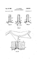
- Figure 3 shows the blanked shoe for the novel shoeplate of the instant invention
- Figures 4, 5 and 6 show successive steps in the manufacture of the novel soleplate prior to bonding the soleplate body portion to the shoe
- Figure 7 is a sectional view of a casting die in which the-body portion of the sole plate is bonded to the shoe, and
- Figure 8 illustrates a finishing step in the manufacture of the novel soleplate.
- the soleplate 10 for a smoothing iron of the steam generating type which is constructed in accordance with the instant, invention.
- the soleplate 10 includes a body portion 11 preferably formed of aluminum or aluminum containing metal cast to the desired configuration.
- the body portion 11 so formed possesses a high thermal conductivity and is light in weight.
- An electrical heating element 12 of the rod form is embedded within the body portion 11 and has a configuration generally paralleling the profile of the soleplate.
- a cover 13 overlies a substantial portion of the body 11 and is secured thereto by bolts 14, or the like. The cover 13 cooperates with the body portion 11 to form a steam generating chamber and steam conducting passages for leading the steam to the steam discharge ports 15 which open to the smoothing surface 10' of the iron.
- soleplate structures designed for use in smoothing irons of the steam generating type. It will be understood by those skilled in the art that the aforedescribed features of the soleplate;:are subject to wide modification without departing from the scope of the invention .as hereinafter described.
- the steam discharge ports 15 are formed by tubular inserts 17 embedded within the body portionll of the soleplate 10.
- the tubular inserts 17 extend through the body portion 11 and are-formed of .a corrosion resistant material such asabrass. Ashoe .138 made of a materialhaving a high resistanceio abrasion is'bonded to the body portion 11 andz-to theends. of the tubular inserts 17.
- Carbon steel is.spart-icularly. suitable for the formation of the shoe 18, and-in accordance with the invention, is joined .to the body portionrll-l and the inserts '17 by a suitable bond high mechanical strength .and a high resistance to thermal shock.
- the shoe 18 is formed with recessedchannels 19, hstillustrated in-rFig. 3, whichlead from the steam ports 15 tozdistribute the steam .over the article to which the smoothing surface of the soleplate 10 is applied.
- the shoe-l-Sunder lies thebody portion 11 and forms anabrasionresistant smoothing surface for the soleplate.
- the shoe 18 includes a-peripheral upstanding flange 20, .which is.also bonded to the .body portion 11 and provides. protectionzforithe edges of the soleplate 10.
- a sheath '21 of corrosion resistant material such as nickel, is applied to the smoothing surface 10 formed :by the shoe .18.
- the sheath 21 extends upwardly a short dis- .tance into the steam discharge ports 15 so asto cover the junction of the shoe 18 with the tubular insert 17, a-ndtoprovide corrosion protection at this point also.
- the corrosion "resistant sheath 21 is plated with chrome -22- to-present a:pleasing appearance to the user.
- the smoothing surface so formed will have the desirable -'featuresof high-corrosion resistance, high resistance to abrasion and-will have a bright non-tarnishingsurface that can be maintained in satisfactory condition for the life of the smoothing iron.
- FIG. 3 there is illustrated a shoe 1-8 which is formed by a die cutting and drawing or stamping operation to the iHustratedconfiguration, having a profile generally "similar-to that of the finished soleplate.
- the blanked shoe 1 8 includes a peripheral upstanding flange 120 terminating in a laterally extending flange 25, which is formed --With a pair of projecting'ears 26 having slots 27 for a purpose to be'described hereinafter.
- the blank is-stamped with a plurality of dimples 28 to locate the-steam discharge ports in the finished soleplate 10.
- -'I-he-dimples 28 arearrangedin two rows of four each, the rows being arranged to substantially parallel the oppositeedges of the soleplate, in accordance with the distribution of the steam ports 15 as previously described.
- Recessed channels "19 for distributing the steam under the smoothing surface ofthe soleplate 10 are also formed in-the blankedshoe 18 by the stamping operation, and extend from the dimples 28.
- the sheath 21 is bonded to the shoe 18 and is most coni nt ap l l y a eave i na plat n op ra io
- a sufiicient amount of the plated material is,.deposited as tocover a short length of the inner surface of the plug 29, so that the sheath 21 will extend over the junction of the shoe 18and the plug 29.
- the bevelled edge 31 facilitates the plating operation .onthe junction of the shoe 18 and the plug 29. 1
- the blanked shoe 18 with the sheath 21 andthe bonded plugs 29 is then placedin a suitablejmold, illustrated in Fig. 7, for die casting of the sole plate bodyportion 11 onto the shoe 18.
- a suitablejmold illustrated in Fig. 7, for die casting of the sole plate bodyportion 11 onto the shoe 18.
- Such mold may comprise mating mold parts 32, 33.
- the mold parts 32, 33 are initially separated for placement therein of the shoe 18.
- Themold part-32 also includes a pairof locating pins 37, one oneach side of the mold cavity 35 whichpins are adaptedsto be received within thefslots 27 formed .in the ears26 projecting from the shoe 18.
- the pins 37 operate to aliguithe shoe -18 for placement of the plugs 29 withinthe recesses 36.
- the face of the mold part 33 is formed-with a surface contour which is complementary to that of-the shoe 18 to provide a backing therefor during-the casting operation.
- the molten-metal is forcedinto the die cavity 35 by a plunger 38 applyingpressure to the molten metal and feedingit through the passageway 39.
- the molten metal 40 flows through the passage 39 and into the die cavity 35 tofillthe latter, the pressureof the metal forcing the shoe 18 against the face of the moldpart 33.
- the laterally extending flange 25 is removed, leaving the soleplate in a semi-finished condition with the upstanding rim flange 20 covering the edge of the body portion 11.
- the partially finished soleplate is then placed on a suitable fixture of a conventional form and a milling cutter 42 passed over the upper surface of the body portion 11.
- the milling cutter 42 reduces the upper surface of the body portion 11 to a flat, substantially smooth surface for the application thereto of the cover plate 13 to form a water tight seal between the cover plate 13 and the body portion 11 for the purpose of defining the steam passages therebetween.
- the closed ends of the inserts 29 are also removed, thereby opening the ends thereof and forming the tubular insert 17 as illustrated in Figs. 1 and 2.
- the next step in the formation of the novel soleplate is to polish and bufi the corrosion resistant sheath 21.
- a flash chrome plate 22 is then applied to the sheath 21 in a known manner for the purpose of enhancing the appearance of the smoothing surface 10' of the soleplate 10.
- the chrome plated surface may be maintained in a highly polished condition for the life of the iron.
- a composite soleplate for smoothing irons comprising a body portion of aluminum having a high heat conductivity, tubular inserts embedded in the body portion extending between the underside of the body portion and the opposite face thereof forming steam passages for the delivery of steam to the smoothing surface of the soleplate, a highly abrasion resistant steel shoe bonded to the underside of the body portion and the contiguous end portions of the inserts, a non-corrosive sheath of nickel covering the shoe and extending into the inserts to cover the junction of the shoe and the inserts.
Landscapes
- Engineering & Computer Science (AREA)
- Textile Engineering (AREA)
- Punching Or Piercing (AREA)
Description
1958 c. w. STUDER 2,846,793
SMOOTHING IRON S OLEPLATE Filed April 21, 1955 v 3 Sheets-Sheet 1 Aug. 12, 1958 Filed April 21. 1955 'C. W. STUDER SMOOTHING IRON 'SOLEPLATE 3 Sheets-Sheet 3 7 Fla. 7
order to present a pleasing appearance.
United States Patent SMOOTHING IRON SOLEPLATE Clair W. Studer, North Canton, Ohio, assignor to The l-Ifogvl'ltir Company, North Canton, Ohio, a corporation 0 0 Application April 21, 1955, Serial No. 502,764
2 Claims. (CI. 3877) The instant invention relates to the manufacture of soleplates for smoothing irons and more particularly to a novel composite soleplate for such irons and the process of manufacturing such soleplates.
Smoothing irons generally comprise an electrically heated soleplate formed with a smoothing surface, the soleplate including an embedded electrical heating element, usually of a rod type, for heating the smoothing surface. In smoothing irons of the steam generating type, the embedded heating element also serves to supply heat to a boiler for the generation of steam therein. It is customary in the art to form the body of the soleplate of a material having a high heat conductivity, such as aluminum or an aluminum containing metal, preferably a relatively hard aluminum copper alloy. An aluminum sole plate is very desirable because of the feature of high thermal conductivity as well as light weight, pleasing appearance and high corrosion resistance. Such sole plates may be polished to enhance the appearance thereof; however, the sole plates constructed of aluminum do not possess a high resistance to abrasion and are subject to scratching and discoloration so that after continued use, the smoothing surface of the sole plate will present an unpleasing appearance to user.
In accordance with the instant invention, the soleplate of the smoothing iron is formed of aluminum or an aluminum containing metal so as to retain the aforementioned desirable features of the aluminum in the soleplate, and an abrasion resistant shoe is applied to the underside of the aluminum soleplate for protecting the same. The shoe is bonded to the aluminum body by a bond having a high mechanical strength and high resistance to thermal shock. The abrasion resistant shoe applied to the body of the soleplate in turn has applied thereto a sheath of highly corrosion resistant material, which is chrome plated for appearance purposes. There is thus provided a composite smoothing surface on the underside of the soleplate, which surface includes thehighly desirable features of high resistance to abrasion, a high resistance to corrosion and presents a pleasing appearance to the user, the smoothing surface so formed not being subject to marring or discoloration. The aluminum body of the soleplate meanwhile retains the features of a high thermal conductivity for most efiicient heating of the smoothing surface.
More specifically, the novel sole plate of the instant invention comprises an aluminum body portion to which is bonded a shoe made of a hard carbon steel, the bond being such as to have a high mechanical strength and'a high resistance to thermal shock. The steel shoe provides the smoothing surface with a high resisance to abrasion. The shoe in turn is plated with nickel or like 'material having a high resistance to corrosion, forming a sheath over the shoe for protecting the same against corrosion. The sheath in turn is platedwith chrome in I It will be apparent that the invention is equallyapplicable to the for- 2,846,793 Patented Aug. 12, 1958 2 mation of the smoothing surface of irons of the dry 0 steam generating type.
It is, accordingly, the prime object of the instant invention to provide a novel sole plate structure for smoothing irons, of a composite construction in which the smoothing surface has a high resistance to abrasion, a high resistance to corrosion and a pleasing appearance.
It is a further object of the instant invention to provide a novel sole plate for smoothing irons having a composite construction, in which there is provided a light weight soleplate body having a high thermal conductivity and a smoothing surface comprising a shoe of steel having a high abrasion resistance, and a sheath of nickel having a high resistance to corrosion applied to the shoe, said sheath being chrome plated to give the soleplate a pleasing appearance.
It is also .an object of the instant invention to provide a novel method for constructing sole plates for smoothing irons in which the soleplate is of a composite construction, and the smoothing surface thereof has a high abrasion resistance, a high resistance to corrosion and presents a pleasing appearance to the user.
While the invention has been generally described, it will be best understood by those skilled in the art from a consideration of the detailed description of a preferred embodiment of the invention which follows, reference being had to the drawings in which:
Figure l is a perspective view, partly in section, of a smoothing iron soleplate constructed in accordance with the instant invention,
Figure 2 is a sectional view of the soleplate illustrated in Fig. 1 showing certain details of construction,
Figure 3 shows the blanked shoe for the novel shoeplate of the instant invention,
Figures 4, 5 and 6 show successive steps in the manufacture of the novel soleplate prior to bonding the soleplate body portion to the shoe,
Figure 7 is a sectional view of a casting die in which the-body portion of the sole plate is bonded to the shoe, and
Figure 8 illustrates a finishing step in the manufacture of the novel soleplate.
The instant invention is described herein as applied to a soleplate for a smoothing iron of the steam generating type. However, it will be apparent to those skilled in the art that the invention may be utilized to equal advantage in the construction of sole plates for dry irons as well as those of the steam generating type.
Referring to Fig. 1, there is illustrated a soleplate 10 for a smoothing iron of the steam generating type which is constructed in accordance with the instant, invention. The soleplate 10 includes a body portion 11 preferably formed of aluminum or aluminum containing metal cast to the desired configuration. The body portion 11 so formed possesses a high thermal conductivity and is light in weight. An electrical heating element 12 of the rod form is embedded within the body portion 11 and has a configuration generally paralleling the profile of the soleplate. A cover 13 overlies a substantial portion of the body 11 and is secured thereto by bolts 14, or the like. The cover 13 cooperates with the body portion 11 to form a steam generating chamber and steam conducting passages for leading the steam to the steam discharge ports 15 which open to the smoothing surface 10' of the iron.
soleplate structures .designed for use in smoothing irons of the steam generating type. It will be understood by those skilled in the art that the aforedescribed features of the soleplate;:are subject to wide modification without departing from the scope of the invention .as hereinafter described.
:Inaccordance\With the instant invention, the steam discharge ports 15 are formed by tubular inserts 17 embedded within the body portionll of the soleplate 10. The tubular inserts 17 extend through the body portion 11 and are-formed of .a corrosion resistant material such asabrass. Ashoe .138 made of a materialhaving a high resistanceio abrasion is'bonded to the body portion 11 andz-to theends. of the tubular inserts 17. Carbon steel is.spart-icularly. suitable for the formation of the shoe 18, and-in accordance with the invention, is joined .to the body portionrll-l and the inserts '17 by a suitable bond high mechanical strength .and a high resistance to thermal shock. The shoe 18 is formed with recessedchannels 19, hstillustrated in-rFig. 3, whichlead from the steam ports 15 tozdistribute the steam .over the article to which the smoothing surface of the soleplate 10 is applied.
The shoe-l-Sunderlies thebody portion 11 and forms anabrasionresistant smoothing surface for the soleplate. The shoe 18 includes a-peripheral upstanding flange 20, .which is.also bonded to the .body portion 11 and provides. protectionzforithe edges of the soleplate 10.
inorder .to protect the shoe 18 against corrosion, a sheath '21 of corrosion resistant material, such as nickel, is applied to the smoothing surface 10 formed :by the shoe .18. The sheath 21 extends upwardly a short dis- .tance into the steam discharge ports 15 so asto cover the junction of the shoe 18 with the tubular insert 17, a-ndtoprovide corrosion protection at this point also. The corrosion "resistant sheath 21 is plated with chrome -22- to-present a:pleasing appearance to the user. The smoothing surface so formed will have the desirable -'featuresof high-corrosion resistance, high resistance to abrasion and-will have a bright non-tarnishingsurface that can be maintained in satisfactory condition for the life of the smoothing iron.
The novel method of manufacturing-the soleplate of the instant invention will now be described. Referring -to-=Fig. 3, there is illustrated a shoe 1-8 which is formed by a die cutting and drawing or stamping operation to the iHustratedconfiguration, having a profile generally "similar-to that of the finished soleplate. The blanked shoe 1 8 includes a peripheral upstanding flange 120 terminating in a laterally extending flange 25, which is formed --With a pair of projecting'ears 26 having slots 27 for a purpose to be'described hereinafter. The blank ;is-stamped with a plurality of dimples 28 to locate the-steam discharge ports in the finished soleplate 10. -'I-he-dimples 28 arearrangedin two rows of four each, the rows being arranged to substantially parallel the oppositeedges of the soleplate, in accordance with the distribution of the steam ports 15 as previously described.
Recessed channels "19 for distributing the steam under the smoothing surface ofthe soleplate 10 are also formed in-the blankedshoe 18 by the stamping operation, and extend from the dimples 28.
' 'I'heiblankshoe 18 isthen placed on a fixture or support of any suitable form-and aplurality of inserts in the form -of solid cylindrical plugs 29, made of brass or like noncorrosive material, are placed on the shoe 18, one in alignment-with each of the dimples 28. The cylindrical plugs '29 are then bonded to the blanked shoe 18 by welding or brazing 30. The length of the plugs 29 is such that they will project slightly above the upper surface of the body portion 11 when the latter is in its unfinished state after it is cast onto the shoe 18, as will be described in greater detail hereinafter.
' The shoe 18 with the plugs 29 bonded thereto is removed from the aforementioned fixture and secured in a second fixture of a suitable form which is adapted ,4 toholdthe plugs .29 wit heundersidenf theshoe l exposed. A drill 31 is then applied to each of the plugs 29 drilling through the blanked shoe 18 and into the plugs 29 for giving the latter a hollow cylindrical configuration. It will be seen in Fig. 5 that the plugs 29 are not drilled through to the ends thereof, but rather the ends remain closed and the plugs 29 are drilled through only to a length approximately eq al to or slightly in excess of the finished length of the tubular insert 17 illustrated in Fig. l and 2. Abe'velled edge 31 is formed at the junction of the plugs 29 and the blanked shoe 18 to avoid a sharp bend at this point for the purpose of facilitating the next step in the formation of the novel soleplate.
A sheath 21 of corrosion resistant material, such as nickel, is now applied to the underside of the shoe 18. The sheath 21 is bonded to the shoe 18 and is most coni nt ap l l y a eave i na plat n op ra io A sufiicient amount of the plated material is,.deposited as tocover a short length of the inner surface of the plug 29, so that the sheath 21 will extend over the junction of the shoe 18and the plug 29. The bevelled edge 31 facilitates the plating operation .onthe junction of the shoe 18 and the plug 29. 1
The blanked shoe 18 with the sheath 21 andthe bonded plugs 29 is then placedin a suitablejmold, illustrated in Fig. 7, for die casting of the sole plate bodyportion 11 onto the shoe 18. Such mold may comprise mating mold parts 32, 33. The mold parts 32, .33 .areguided into juxtaposed relation .by a pair .of aligning pins 34 to form an internal mold cavity 35for the formation .of the :body portion 11. The mold parts 32, 33 are initially separated for placement therein of the shoe 18. .Theone mold part 32 isformed with aplurality of recesses 36 which are aligned with the plugs- 29 on the shoe v18 toreceivethe closed ends of the plugs :29 forholding and positioning the shoe 18 =withinlthernold cavity. Themold part-32 also includesa pairof locating pins 37, one oneach side of the mold cavity 35 whichpins are adaptedsto be received within thefslots 27 formed .in the ears26 projecting from the shoe 18. The pins 37 operate to aliguithe shoe -18 for placement of the plugs 29 withinthe recesses 36. When the shoe'18 hasbeen positioned-on the mold part 32 as above described, the mold part 33 is closed thereon, and the mold maintained in a sealed condition. The face of the mold part 33 is formed-with a surface contour which is complementary to that of-the shoe 18 to provide a backing therefor during-the casting operation. The molten-metal is forcedinto the die cavity 35 by a plunger 38 applyingpressure to the molten metal and feedingit through the passageway 39. The molten metal 40 flows through the passage 39 and into the die cavity 35 tofillthe latter, the pressureof the metal forcing the shoe 18 against the face of the moldpart 33.
heating element .will .be .embeddedwithin the body-portion 11.of. the soleplatelt) during, the castingoper tion. This is .a conventional ,procedure. in .the art, ,and ,-accordingly, it is.not deemed necessary tojillustrate the same in t awin n th i ectio a y w th i castin ,mold illustrated-in Fig. 7, the castbodyportiongll has been shown in ,section, with-the section .line passing through four .of the plugs 29 ,on one side of th b ody portion 11 for the purpose of providing per natation. 1
' The cast bodyportion 11 and the bonded shoe 18,
when removed from the casting dies 32, 33, includes flash 41 which may be removed by grinding, or a like operation. Simultaneously, with the removal of the flash 41, the laterally extending flange 25 is removed, leaving the soleplate in a semi-finished condition with the upstanding rim flange 20 covering the edge of the body portion 11. The partially finished soleplate is then placed on a suitable fixture of a conventional form and a milling cutter 42 passed over the upper surface of the body portion 11. The milling cutter 42 reduces the upper surface of the body portion 11 to a flat, substantially smooth surface for the application thereto of the cover plate 13 to form a water tight seal between the cover plate 13 and the body portion 11 for the purpose of defining the steam passages therebetween. During the operation of milling the top surface of the body portion, the closed ends of the inserts 29 are also removed, thereby opening the ends thereof and forming the tubular insert 17 as illustrated in Figs. 1 and 2.
The next step in the formation of the novel soleplate is to polish and bufi the corrosion resistant sheath 21. A flash chrome plate 22 is then applied to the sheath 21 in a known manner for the purpose of enhancing the appearance of the smoothing surface 10' of the soleplate 10. The chrome plated surface may be maintained in a highly polished condition for the life of the iron.
The instant invention in a novel soleplate for smoothing irons, and the process of manufacturing that soleplate has been described herein as embodied in a preferred construction. It will be understood by those skilled in the art that the described embodiment is subject to modifications falling within the spirit of the invention, and
6 accordingly, it is not intended that the scope of the invention be limited except as set forth in the claims which follow.
I claim:
1. A composite soleplate for smoothing irons comprising a body portion of aluminum having a high heat conductivity, tubular inserts embedded in the body portion extending between the underside of the body portion and the opposite face thereof forming steam passages for the delivery of steam to the smoothing surface of the soleplate, a highly abrasion resistant steel shoe bonded to the underside of the body portion and the contiguous end portions of the inserts, a non-corrosive sheath of nickel covering the shoe and extending into the inserts to cover the junction of the shoe and the inserts.
2. A composite soleplate for smoothing irons as recited in claim 1 in which the tubular inserts are formed of brass and are brazed to the shoe, steam passages formed in the smoothing surface of the soleplate comprising recesses in the shoe leading from the tubular inserts, and a heating element embedded in the body portion for heating the soleplate and generating steam.
References Cited in the file of this patent UNITED STATES PATENTS 1,749,596 McArdle Mar. 4, 1930 2,270,316 Kuhn et a1. Jan. 20, 1942 2,298,113 Wly Oct. 6, 1942 2,344,098 Lucia Mar. 14, 1944 2,529,348 Mustee Nov. 7, 1950 2,707,324 Walter May 3, 1955
Priority Applications (1)
| Application Number | Priority Date | Filing Date | Title |
|---|---|---|---|
| US502764A US2846793A (en) | 1955-04-21 | 1955-04-21 | Smoothing iron soleplate |
Applications Claiming Priority (1)
| Application Number | Priority Date | Filing Date | Title |
|---|---|---|---|
| US502764A US2846793A (en) | 1955-04-21 | 1955-04-21 | Smoothing iron soleplate |
Publications (1)
| Publication Number | Publication Date |
|---|---|
| US2846793A true US2846793A (en) | 1958-08-12 |
Family
ID=23999317
Family Applications (1)
| Application Number | Title | Priority Date | Filing Date |
|---|---|---|---|
| US502764A Expired - Lifetime US2846793A (en) | 1955-04-21 | 1955-04-21 | Smoothing iron soleplate |
Country Status (1)
| Country | Link |
|---|---|
| US (1) | US2846793A (en) |
Cited By (27)
| Publication number | Priority date | Publication date | Assignee | Title |
|---|---|---|---|---|
| US4089128A (en) * | 1976-04-13 | 1978-05-16 | Baumgartner Erich R | Smoothing or pressing iron having a sole body consisting at least partially of a glass material |
| US4122615A (en) * | 1976-04-13 | 1978-10-31 | Baumgartner Erich R | Smoothing iron sole |
| US4471541A (en) * | 1980-09-24 | 1984-09-18 | Seb S.A. | Steam iron sole-plate cover and its method of assembly |
| US4479315A (en) * | 1983-09-16 | 1984-10-30 | Leonard Automatics, Inc. | Steaming apparatus for a vertical side chest in a trouser presser |
| DE3603409A1 (en) * | 1985-06-05 | 1986-12-11 | Rowenta-Werke Gmbh, 6050 Offenbach | ELECTRICALLY HEATED STEAM IRON |
| DE3644211A1 (en) * | 1985-12-24 | 1987-08-27 | Braun Ag | Pressing iron sole plate |
| US4995177A (en) * | 1989-01-04 | 1991-02-26 | Seb S.A. | Laundry-iron sole-plate formed by assembling together a plurality of metal sheets brazed to each other |
| US5025578A (en) * | 1988-08-25 | 1991-06-25 | Braun Aktiengesellschaft | Roughened smoothing iron soleplate having an anti-corrosive, scratch-resistant and easily slidable coating thereon |
| US5105525A (en) * | 1988-08-25 | 1992-04-21 | Braun Aktiengesellschaft | Process for making a smoothing iron soleplate |
| US5146700A (en) * | 1991-10-31 | 1992-09-15 | Coors Technical Ceramics Company | Steam iron with bonded ceramic and aluminum components |
| FR2700784A1 (en) * | 1993-01-25 | 1994-07-29 | Seb Sa | Multi-layer smoothing-iron sole made from colaminated materials |
| FR2705374A1 (en) * | 1993-05-14 | 1994-11-25 | Bosch Siemens Hausgeraete | Sole for an electric iron. |
| US5384944A (en) * | 1992-11-09 | 1995-01-31 | Textilmaschinenfabrik Dr. Ernst Fehrer Aktiengesellschaft | Needling plate with recesses on downstream edges of the through holes |
| USD376455S (en) | 1995-11-27 | 1996-12-10 | Black & Decker Inc. | Soleplate for a steam iron |
| US5613310A (en) * | 1994-06-24 | 1997-03-25 | Braun Aktiengesellschaft | Edge shape in a smoothing iron |
| US5615500A (en) * | 1995-11-03 | 1997-04-01 | Black & Decker Inc. | Iron with improved connection of soleplate and steam chamber cover |
| USD381153S (en) * | 1995-11-27 | 1997-07-15 | Black & Decker Inc. | Soleplate for a steam iron |
| US5749165A (en) * | 1994-04-06 | 1998-05-12 | Braun Aktiengesellschaft | Electric pressing iron with coated soleplate |
| FR2776681A1 (en) * | 1998-03-27 | 1999-10-01 | Moulinex Sa | ELECTRIC IRON SOLE |
| US6134817A (en) * | 1996-01-17 | 2000-10-24 | Moulinex S.A. | Soleplate for an iron |
| US6216369B1 (en) * | 1997-09-05 | 2001-04-17 | Braun Aktiengesellschaft | Steam iron with steam discharge ahead of and along the side of the iron |
| US6381884B1 (en) * | 1998-11-13 | 2002-05-07 | Moulinex, S.A. | Steam iron sole plate |
| US20050183296A1 (en) * | 2004-01-30 | 2005-08-25 | Celaya, Emparanza Y Galdos, Internacional, S.A. | Domestic steam irons having a vaporisation chamber and fitted with independent heat element |
| US20090165341A1 (en) * | 2006-05-16 | 2009-07-02 | Koninklijke Philips Electronics N.V. | Soleplate |
| USD630399S1 (en) * | 2008-11-05 | 2011-01-04 | Rowenta Werke Gmbh | Soleplate for laundry iron |
| USD635317S1 (en) * | 2009-12-01 | 2011-03-29 | Calor | Soleplate for a laundry iron |
| USD804129S1 (en) * | 2016-10-12 | 2017-11-28 | Sunbeam Products, Inc. | Iron soleplate |
Citations (6)
| Publication number | Priority date | Publication date | Assignee | Title |
|---|---|---|---|---|
| US1749596A (en) * | 1927-02-02 | 1930-03-04 | Michael W Mcardle | Sole plate for laundry irons |
| US2270316A (en) * | 1941-07-07 | 1942-01-20 | American Electrical Heater Co | Finish for working surface of laundry irons and the like |
| US2298113A (en) * | 1940-12-07 | 1942-10-06 | Westinghouse Electric & Mfg Co | Lightweight electric iron |
| US2344098A (en) * | 1940-08-16 | 1944-03-14 | Silex Co | Combination pressing and steaming iron |
| US2529348A (en) * | 1948-10-27 | 1950-11-07 | E L Mustee And Sons Inc | Method of making sacrifice rods for water tanks |
| US2707324A (en) * | 1951-07-14 | 1955-05-03 | Dayton Steel Foundry Co | Casting and processing of cast metal articles |
-
1955
- 1955-04-21 US US502764A patent/US2846793A/en not_active Expired - Lifetime
Patent Citations (6)
| Publication number | Priority date | Publication date | Assignee | Title |
|---|---|---|---|---|
| US1749596A (en) * | 1927-02-02 | 1930-03-04 | Michael W Mcardle | Sole plate for laundry irons |
| US2344098A (en) * | 1940-08-16 | 1944-03-14 | Silex Co | Combination pressing and steaming iron |
| US2298113A (en) * | 1940-12-07 | 1942-10-06 | Westinghouse Electric & Mfg Co | Lightweight electric iron |
| US2270316A (en) * | 1941-07-07 | 1942-01-20 | American Electrical Heater Co | Finish for working surface of laundry irons and the like |
| US2529348A (en) * | 1948-10-27 | 1950-11-07 | E L Mustee And Sons Inc | Method of making sacrifice rods for water tanks |
| US2707324A (en) * | 1951-07-14 | 1955-05-03 | Dayton Steel Foundry Co | Casting and processing of cast metal articles |
Cited By (37)
| Publication number | Priority date | Publication date | Assignee | Title |
|---|---|---|---|---|
| US4122615A (en) * | 1976-04-13 | 1978-10-31 | Baumgartner Erich R | Smoothing iron sole |
| US4089128A (en) * | 1976-04-13 | 1978-05-16 | Baumgartner Erich R | Smoothing or pressing iron having a sole body consisting at least partially of a glass material |
| US4471541A (en) * | 1980-09-24 | 1984-09-18 | Seb S.A. | Steam iron sole-plate cover and its method of assembly |
| US4479315A (en) * | 1983-09-16 | 1984-10-30 | Leonard Automatics, Inc. | Steaming apparatus for a vertical side chest in a trouser presser |
| DE3603409A1 (en) * | 1985-06-05 | 1986-12-11 | Rowenta-Werke Gmbh, 6050 Offenbach | ELECTRICALLY HEATED STEAM IRON |
| FR2583077A1 (en) * | 1985-06-05 | 1986-12-12 | Rowenta Werke Gmbh | STEAM IRON WITH ELECTRIC HEATING |
| US4658520A (en) * | 1985-06-05 | 1987-04-21 | Rowenta-Werke Gmbh | Steam iron soleplate |
| DE3644211A1 (en) * | 1985-12-24 | 1987-08-27 | Braun Ag | Pressing iron sole plate |
| US5105525A (en) * | 1988-08-25 | 1992-04-21 | Braun Aktiengesellschaft | Process for making a smoothing iron soleplate |
| US5025578A (en) * | 1988-08-25 | 1991-06-25 | Braun Aktiengesellschaft | Roughened smoothing iron soleplate having an anti-corrosive, scratch-resistant and easily slidable coating thereon |
| US4995177A (en) * | 1989-01-04 | 1991-02-26 | Seb S.A. | Laundry-iron sole-plate formed by assembling together a plurality of metal sheets brazed to each other |
| US5146700A (en) * | 1991-10-31 | 1992-09-15 | Coors Technical Ceramics Company | Steam iron with bonded ceramic and aluminum components |
| WO1993009282A1 (en) * | 1991-10-31 | 1993-05-13 | Coors Technical Ceramics Company | Steam iron with bonded ceramic and aluminum components__________ |
| US5384944A (en) * | 1992-11-09 | 1995-01-31 | Textilmaschinenfabrik Dr. Ernst Fehrer Aktiengesellschaft | Needling plate with recesses on downstream edges of the through holes |
| FR2700784A1 (en) * | 1993-01-25 | 1994-07-29 | Seb Sa | Multi-layer smoothing-iron sole made from colaminated materials |
| WO1994017236A1 (en) * | 1993-01-25 | 1994-08-04 | Seb S.A. | Multilayer iron soleplate made of colaminate materials |
| US5619813A (en) * | 1993-01-25 | 1997-04-15 | Seb S.A. | Multilayer iron soleplate made up of co-laminated materials |
| FR2705374A1 (en) * | 1993-05-14 | 1994-11-25 | Bosch Siemens Hausgeraete | Sole for an electric iron. |
| US5749165A (en) * | 1994-04-06 | 1998-05-12 | Braun Aktiengesellschaft | Electric pressing iron with coated soleplate |
| US5613310A (en) * | 1994-06-24 | 1997-03-25 | Braun Aktiengesellschaft | Edge shape in a smoothing iron |
| EP0771900A2 (en) | 1995-11-03 | 1997-05-07 | Black & Decker Inc. | Iron with improved connection of soleplate and steam chamber cover |
| US5615500A (en) * | 1995-11-03 | 1997-04-01 | Black & Decker Inc. | Iron with improved connection of soleplate and steam chamber cover |
| USD381153S (en) * | 1995-11-27 | 1997-07-15 | Black & Decker Inc. | Soleplate for a steam iron |
| USD376455S (en) | 1995-11-27 | 1996-12-10 | Black & Decker Inc. | Soleplate for a steam iron |
| US6134817A (en) * | 1996-01-17 | 2000-10-24 | Moulinex S.A. | Soleplate for an iron |
| US6216369B1 (en) * | 1997-09-05 | 2001-04-17 | Braun Aktiengesellschaft | Steam iron with steam discharge ahead of and along the side of the iron |
| US6393741B1 (en) | 1998-03-27 | 2002-05-28 | Moulinex S.A. | Electric iron sole plate |
| FR2776681A1 (en) * | 1998-03-27 | 1999-10-01 | Moulinex Sa | ELECTRIC IRON SOLE |
| WO1999050497A1 (en) * | 1998-03-27 | 1999-10-07 | Moulinex S.A. | Electric iron sole plate |
| US6381884B1 (en) * | 1998-11-13 | 2002-05-07 | Moulinex, S.A. | Steam iron sole plate |
| US20050183296A1 (en) * | 2004-01-30 | 2005-08-25 | Celaya, Emparanza Y Galdos, Internacional, S.A. | Domestic steam irons having a vaporisation chamber and fitted with independent heat element |
| US7096612B2 (en) * | 2004-01-30 | 2006-08-29 | Celaya, Emparanza Y Galdos, Internacional, S.A. | Domestic steam irons having a vaporization chamber and fitted with independent heat element |
| US20090165341A1 (en) * | 2006-05-16 | 2009-07-02 | Koninklijke Philips Electronics N.V. | Soleplate |
| US8166681B2 (en) * | 2006-05-16 | 2012-05-01 | Koninklijke Philips Electronics N.V. | Soleplate |
| USD630399S1 (en) * | 2008-11-05 | 2011-01-04 | Rowenta Werke Gmbh | Soleplate for laundry iron |
| USD635317S1 (en) * | 2009-12-01 | 2011-03-29 | Calor | Soleplate for a laundry iron |
| USD804129S1 (en) * | 2016-10-12 | 2017-11-28 | Sunbeam Products, Inc. | Iron soleplate |
Similar Documents
| Publication | Publication Date | Title |
|---|---|---|
| US2846793A (en) | Smoothing iron soleplate | |
| US3930325A (en) | Steam iron soleplate construction | |
| US1834763A (en) | Method of molding and apparatus therefor | |
| US2260593A (en) | Method of making wear resistant surfaces | |
| US2359920A (en) | Abrasive article | |
| US2389588A (en) | Heating apparatus | |
| US2182775A (en) | Method of making dies | |
| US2014955A (en) | Method of making an abrasive tool | |
| US2189709A (en) | Electric steaming iron | |
| US2042953A (en) | Method of making sole plates for sadirons | |
| US3032861A (en) | Method of manufacturing a flatiron | |
| US3099869A (en) | Process of bonding metals | |
| US2846794A (en) | Steam distributor for steam iron | |
| US3260005A (en) | Method of assembling a steam iron base | |
| US3942706A (en) | Steam iron soleplate construction | |
| US2477565A (en) | Electric heating unit and method of making | |
| US2891138A (en) | Method of and apparatus for bonding the head of a golf club to the shaft thereof | |
| US6032837A (en) | Shirt pressing and finishing machine | |
| US2138720A (en) | Sadiron sole plate and method of making | |
| US2301991A (en) | Device for the transmission of electric current from a relatively moved conductive surface | |
| US2625756A (en) | Feed water system for steam irons | |
| US3561686A (en) | Hammermill hammers | |
| US2322103A (en) | Steam electric sadiron | |
| US1037489A (en) | Process of producing patterns for castings, &c. | |
| US1122583A (en) | Segmental brake-shoe. |